EP1275932A2 - Programmaktualisierung in einem Messgerät - Google Patents
Programmaktualisierung in einem Messgerät Download PDFInfo
- Publication number
- EP1275932A2 EP1275932A2 EP02254711A EP02254711A EP1275932A2 EP 1275932 A2 EP1275932 A2 EP 1275932A2 EP 02254711 A EP02254711 A EP 02254711A EP 02254711 A EP02254711 A EP 02254711A EP 1275932 A2 EP1275932 A2 EP 1275932A2
- Authority
- EP
- European Patent Office
- Prior art keywords
- program
- measuring device
- copying
- storage means
- stored
- Prior art date
- Legal status (The legal status is an assumption and is not a legal conclusion. Google has not performed a legal analysis and makes no representation as to the accuracy of the status listed.)
- Granted
Links
Images


Classifications
-
- G—PHYSICS
- G01—MEASURING; TESTING
- G01C—MEASURING DISTANCES, LEVELS OR BEARINGS; SURVEYING; NAVIGATION; GYROSCOPIC INSTRUMENTS; PHOTOGRAMMETRY OR VIDEOGRAMMETRY
- G01C15/00—Surveying instruments or accessories not provided for in groups G01C1/00 - G01C13/00
- G01C15/002—Active optical surveying means
Definitions
- the present invention relates to a measuring device, which comprises functions to display or store measured values and further to display guidance information for operation.
- the programs include a basic program and an application program.
- the basic program comprises a program for converting a signal from a distance measuring unit to a distance, a program for converting a signal from an encoder to an angle, and a program for displaying surveyed values on a display unit.
- the application program calculates or stores the measured values by a procedure according to the surveying operation.
- the basic program and the application program are recorded in a ROM mounted in a circuit substrate.
- the electronic survey instrument is operated according to the programs. New functions can be added, program bug can be repaired, or version of the program can be updated.
- the programs stored in a card may be rewritten for the purpose of repairing program bug or of updating the program version, etc.
- the basic program is incorporated in the survey instrument, and a cover of the instrument must be opened for the purpose of rewriting.
- both the application program and the basic program are incorporated in the instrument.
- a cover of a main unit must be opened, and ROM inserted in the circuit substrate must be replaced.
- the measuring device comprises a program for operating the measuring device, a copying program for rewriting the program or for copying the program, a rewritable first storage means for storing the program, a signal input/output means, and a second storage means for storing the copying program, wherein the program stored in the first storage means is rewritten through a new program inputted through the signal input/output means.
- the present invention provides the measuring device as described above, wherein a program stored in the first storage means is copied by the copying program and is outputted through the signal input/output means.
- the present invention provides the measuring device as described above, wherein the program can be rewritten from a measuring device to another measuring device by operating the copying program of the measuring device provided with the copying program. Also, the present invention provides the measuring device as described above, wherein a plurality of measuring devices can be connected via the signal input/output means, and by operating the copying program, the program stored in the first storage means of a measuring device on an input side can be rewritten by a new program stored in a measuring device on an output side. Further, the present invention provides the measuring device as described above, wherein the signal input/output means is provided with a wireless transmitter/receiver for inputting and outputting a data signal by wireless.
- a measuring device comprising a program for operating the measuring device, a copying program for rewriting the program or for copying the program, a rewritable first storage means for storing the program, a signal input/output means, and a second storage means for storing the copying program, wherein the second storage means further comprises a transfer program for inputting and outputting a program to be rewritten or a program to be copied as a data signal through the input/output means.
- the present invention provides the measuring device as described above, wherein the program stored in the rewritable first storage means is a survey program, the measuring device has a distance measuring and angle measuring function, and the distance measuring and angle measuring function is performed based on the survey program.
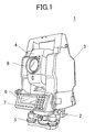
- An electronic survey instrument 1 mainly comprises a base unit 2 fixed on a tripod (not shown), a frame unit 3 rotatable around a vertical axis and mounted on the base unit 2, and a body tube 4 tiltable around a horizontal axis and mounted on the frame unit 3.
- Leveling screws 5 are provided on the base unit 2, and leveling operation of the electronic survey instrument 1 can be performed by adjusting the leveling screws 5.
- a control unit 10 (to be described later) is provided on the frame unit 3, and a display unit 6 and an operation/input unit 7 are further provided.
- a telescope 8 is mounted on the tube body 4, a telescope 8 is mounted.
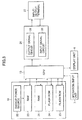
- a vertical angle encoder 11 is mounted on a rotator of the body tube 4.
- a detection signal from the vertical angle encoder 11 is inputted to a vertical angle measuring unit 12.
- the vertical angle measuring unit 12 Based on the signal from the vertical angle encoder 11, the vertical angle measuring unit 12 calculates a tilt angle of the body tube 4, and the result of calculation is inputted to a control arithmetic unit 13.
- a horizontal angle encoder 14 is mounted on a rotator of the frame unit 3.
- a signal from the horizontal angle encoder 14 is inputted to a horizontal angle measuring unit 15.
- the horizontal angle measuring unit 15 counts or stores the signal from the horizontal angle encoder 14.
- the result is inputted to the control arithmetic unit 13, and a horizontal angle is calculated.
- the control arithmetic unit 13 calculates a measuring distance and a measuring angle and controls the electronic survey instrument 1 in operation such as display operation.
- a storage unit 19 connected to the control arithmetic unit 13 comprises semiconductor storage means such as ROM, RAM, flash ROM, etc. Measured values are stored, and a basic program and an application program are stored.
- the storage unit 19 is mounted in advance on a wiring substrate (not shown) of the control arithmetic unit 13.
- the control arithmetic unit 13 drives and controls a distance measuring light projecting unit 16.
- the distance measuring light projecting unit 16 projects a distance measuring light to an object 17.
- the distance measuring light thus projected is reflected by the object 17.
- the reflected distance measuring light is detected by a photodetection unit 18.
- a detection signal is inputted to the control arithmetic unit 13, and the distance is calculated.
- the display unit 6 and the operation/input unit 7 are connected to the control arithmetic unit 13.
- the object 17 is arranged at a predetermined position such as a known point, a measuring point, etc.
- Conditions for measurement, etc. are inputted by the operation/input unit 7, and the data thus inputted are displayed on the display unit 6.
- the control arithmetic unit 13 displays guidance information display such as information on a measuring procedure on the display unit 6. Following the guidance information display, a measuring operator inputs starting of measurement, and the measuring operation is started.
- the distance measuring light is projected from the distance measuring light projecting unit 16.
- the distance measuring light reflected by the object 17 is received by the photodetection unit 18.
- the result of the photodetection is inputted to the control arithmetic unit 13, and the distance to the object 17 is calculated.
- a vertical angle with respect to the object 17 is inputted to the control arithmetic unit 13 from the vertical angle measuring unit 12.
- a horizontal angle is also inputted to the control arithmetic unit 13 from the horizontal angle measuring unit 15.
- the distance measurement result, the vertical angle, and the horizontal angle are displayed on the display unit 6.
- process of measurement is displayed on the display unit 6.
- the display of the inputted data on the display unit 6, or the displays of the guidance information for measurement, the measurement result and the measurement process, etc. are performed in accordance with a program stored in advance in the storage unit 19.
- the present embodiment is provided with a function to rewrite the program stored in the storage unit 19.
- the storage unit 19 comprises a first RAM 21, a second RAM 23, to which a backup power source 22 is connected, a flash ROM 24, and a flash ROM 25.
- the first RAM 21 is a storage means for temporarily storing the data, the program or the calculation result, etc. and the data are stored so far as power is connected.
- the second RAM 23 stores data such as setting values required for operating the electronic survey instrument 1, correction value necessary for calculation, etc. The stored data are maintained by the backup power source 22.
- the flash ROM 24 maintains the stored data without supply of power.
- the flash ROM 24 stores a copying program for copying survey data and for copying the program, a transfer program for transferring the copied data, or a writing program for writing the data transferred from outside to the flash ROM 25. These programs are not rewritable.
- the flash ROM 25 maintains the stored data without supply of power.
- the flash ROM 25 stores a basic control program necessary for operation of hardware in the electronic survey instrument 1, e.g. a program for calculating the vertical angle or the horizontal angle based on a signal from the vertical angle measuring unit 12 or the horizontal angle measuring unit 15, and a program for projecting the distance measuring light from the distance measuring light projecting unit 16, and for receiving the reflected light and for capturing the photodetection signal and for calculating the distance.
- a survey program e.g. a survey sequence program for automatically performing the survey operation, and a display program for displaying the survey result, and the process of survey in various modes on the display unit 6 are stored. These programs are rewritable for the purpose of updating the program version, or of repairing program bug.
- the flash ROM 25 is divided to the flash ROM for the basic program and the flash ROM for the application program.
- An input/output means 26 is connected to the control arithmetic unit 13.
- the input/output means 26 comprises an output signal processing circuit 28 for converting data such as the programs stored in the flash ROM 25 to a form of signal, which can be outputted to outside such as series of signals, and an input signal processing circuit 29 for converting the series of data inputted from outside to a form of signals to be processed at the control arithmetic unit 13.
- an input/output terminal 27 e.g. a 232C terminal
- an external device e.g. other electronic survey instrument
- the input/output terminal connected to the other electronic survey instrument and the copying program is incorporated, it is possible to connect to the other electronic survey instrument via the input/output terminal 27 and to transfer the data from one electronic survey instrument to the other electronic survey instrument.
- the copying program is started by the operation/input unit 7. Also, by the operation from the operation/input unit 7, an old program stored in the flash ROM 25 can be erased and a new program can be rewritten.
- the program can be transferred from the electronic survey instrument where a survey program of new version is stored to the other electronic survey instrument and the program can be rewritten.
- Step 01 The electronic survey instrument A is connected to the electronic survey instrument B via the input/output terminal 27 by a cable.
- the copy source and the copy destination are set by a selector switch, which is used to differentiate the copy source from the copy destination or by a selector switch, which validates only one of the transferred program and the rewritten program.
- the selector switch may be a mechanical switch or a software-oriented switch.
- Step 02 By starting the rewritten program of the electronic survey instrument B, the contents stored in the flash ROM 25 is erased, and it is turned to the rewrite standby status.
- Step 03 The copying program of the electronic survey instrument A is selected and started.
- Step 04 It is checked whether the electronic survey instrument B is ready for data input. If the result of the checking is acceptable (OK), the transfer program is automatically started, and the copying data is transferred to the electronic survey instrument B. If the result of the checking is not acceptable (NO), the copying is stopped. It is displayed on the display unit 6 whether the copying operation has been completed or not. To complete the copying operation, the procedure should be repeated from Step 01 again.
- Step 05 The survey program of the electronic survey instrument A is read.
- Step 06 The survey program thus read is temporarily stored in the first RAM 21.
- Step 07 The survey program of the first RAM 21 is converted to data for sequential delivery by the output signal processing circuit 28. The data are then outputted via the input/output terminal 27 and are transferred to the electronic survey instrument B. The data transferred via the input/output terminal 27 and the input signal processing circuit 29 of the electronic survey instrument B are incorporated, and the data are converted at the input signal processing circuit 29 and are written in the flash ROM 25.
- Step 08 It is checked whether the copying operation has been normally completed or not. If copying is not completed, the procedure is returned to Step 05, and copying operation is further continued. If copying has been normally completed, the completion of copying is displayed on the display unit 6 as soon as the copying program has been completed.
- the data are transferred via the cable, while it may be designed in such manner that a wireless transmitter/receiver is provided in the electronic survey instruments, and the data may be transmitted and received by wireless.
- the electronic survey instruments When the electronic survey instruments are connected with each other via the cable, it may be designed in such manner that a plurality of electronic survey instruments are connected in series so that survey programs of a plurality of electronic survey instruments can be rewritten at the same time.
- a wireless system if one survey instrument is assigned as the copy source survey instrument, a plurality of electronic survey instruments can receive the data at the same time. Then, it is possible to rewrite the survey programs of a plurality of electronic survey instruments at the same time. By repeating copying, programs of many electronic survey instruments can be rewritten easily.
- a measuring device comprises a program for operating the measuring device, a copying program for rewriting the program or for copying the program, a rewritable first storage means for storing the program, a signal input/output means, and a second storage means for storing the copying program, wherein the program stored in the first storage means is rewritten by a new program inputted through the signal input/output means.
Landscapes
- Physics & Mathematics (AREA)
- Engineering & Computer Science (AREA)
- General Physics & Mathematics (AREA)
- Radar, Positioning & Navigation (AREA)
- Remote Sensing (AREA)
- Stored Programmes (AREA)
- Debugging And Monitoring (AREA)
Applications Claiming Priority (2)
| Application Number | Priority Date | Filing Date | Title |
|---|---|---|---|
| JP2001208088A JP2003022191A (ja) | 2001-07-09 | 2001-07-09 | 測定装置 |
| JP2001208088 | 2001-07-09 |
Publications (3)
| Publication Number | Publication Date |
|---|---|
| EP1275932A2 true EP1275932A2 (de) | 2003-01-15 |
| EP1275932A3 EP1275932A3 (de) | 2003-07-30 |
| EP1275932B1 EP1275932B1 (de) | 2010-03-17 |
Family
ID=19043970
Family Applications (1)
| Application Number | Title | Priority Date | Filing Date |
|---|---|---|---|
| EP02254711A Expired - Lifetime EP1275932B1 (de) | 2001-07-09 | 2002-07-04 | Programmaktualisierung in einem Messgerät |
Country Status (4)
| Country | Link |
|---|---|
| US (1) | US6799142B2 (de) |
| EP (1) | EP1275932B1 (de) |
| JP (1) | JP2003022191A (de) |
| DE (1) | DE60235678D1 (de) |
Families Citing this family (4)
| Publication number | Priority date | Publication date | Assignee | Title |
|---|---|---|---|---|
| US8612270B2 (en) * | 2004-06-12 | 2013-12-17 | James K. Hazy | System and method to simulate the impact of leadership activity |
| JP2006038581A (ja) * | 2004-07-26 | 2006-02-09 | Topcon Corp | 測量装置の管理システム |
| US8539685B2 (en) | 2011-01-20 | 2013-09-24 | Trimble Navigation Limited | Integrated surveying and leveling |
| EP3253305B1 (de) * | 2015-03-26 | 2020-07-22 | Boston Scientific Scimed, Inc. | Systeme zur vaskularen okklusion |
Family Cites Families (14)
| Publication number | Priority date | Publication date | Assignee | Title |
|---|---|---|---|---|
| US5752040A (en) * | 1991-09-30 | 1998-05-12 | Canon Kabushiki Kaisha | Image processing apparatus which can update program |
| JPH08285577A (ja) * | 1995-04-19 | 1996-11-01 | Asahi Optical Co Ltd | トータルステーション |
| US6067500A (en) * | 1995-08-14 | 2000-05-23 | Aisin Aw Co., Ltd. | Navigation system |
| JP3202154B2 (ja) * | 1995-09-29 | 2001-08-27 | 松下電器産業株式会社 | 車載ナビゲーション装置 |
| JPH1010931A (ja) * | 1996-06-27 | 1998-01-16 | Sharp Corp | 画像形成装置 |
| US6275911B1 (en) * | 1996-09-20 | 2001-08-14 | Denso Corporation | Memory writing device for an electronic device |
| JPH10269074A (ja) * | 1997-03-25 | 1998-10-09 | Zaou Nikon:Kk | 測量機、測量機へのプログラムインストール方法及び測量機の組立方法 |
| JPH1136972A (ja) * | 1997-07-22 | 1999-02-09 | Mitsubishi Electric Corp | 自動車用制御装置 |
| JP3626328B2 (ja) * | 1997-07-24 | 2005-03-09 | 三菱電機株式会社 | 車両用制御装置 |
| US6034722A (en) * | 1997-11-03 | 2000-03-07 | Trimble Navigation Limited | Remote control and viewing for a total station |
| JP2000267857A (ja) * | 1999-03-17 | 2000-09-29 | Oki Data Corp | ファクシミリメンテナンスシステム |
| JP2001005671A (ja) * | 1999-06-23 | 2001-01-12 | Denso Corp | データ送信システム |
| JP3545659B2 (ja) * | 1999-10-21 | 2004-07-21 | 松下電器産業株式会社 | プログラム更新方法および通信端末装置 |
| JP2001209543A (ja) * | 2000-01-28 | 2001-08-03 | Nec Ic Microcomput Syst Ltd | フラッシュ・マイコンにおけるプログラム書き換え方法 |
-
2001
- 2001-07-09 JP JP2001208088A patent/JP2003022191A/ja active Pending
-
2002
- 2002-06-26 US US10/180,263 patent/US6799142B2/en not_active Expired - Lifetime
- 2002-07-04 DE DE60235678T patent/DE60235678D1/de not_active Expired - Lifetime
- 2002-07-04 EP EP02254711A patent/EP1275932B1/de not_active Expired - Lifetime
Also Published As
| Publication number | Publication date |
|---|---|
| US6799142B2 (en) | 2004-09-28 |
| EP1275932A3 (de) | 2003-07-30 |
| US20030009310A1 (en) | 2003-01-09 |
| JP2003022191A (ja) | 2003-01-24 |
| DE60235678D1 (de) | 2010-04-29 |
| EP1275932B1 (de) | 2010-03-17 |
Similar Documents
| Publication | Publication Date | Title |
|---|---|---|
| US5488558A (en) | Handy computer with built-in digital camera and spot state recording method using the same | |
| US20020018122A1 (en) | Method and arrangement for carrying out an information flow and data flow for geodetic instruments | |
| EP2098820B1 (de) | Vorrichtung zum Erfassen von geographischen Daten | |
| KR100835759B1 (ko) | 이미지 프로젝터, 경사각 검출방법, 및 투사 이미지정정방법 | |
| JP2020008423A (ja) | 施工管理システム | |
| CN108319875A (zh) | 传感器支援系统、终端、传感器以及传感器支援方法 | |
| US6799142B2 (en) | Measuring device | |
| US20030090567A1 (en) | Object distance display apparatus | |
| JP2005275327A (ja) | 投射表示装置 | |
| AU615382B2 (en) | Surveying apparatus | |
| CN109154500A (zh) | 激光水准检查 | |
| US10502560B2 (en) | Optoelectronic measuring device having magnetic compass and compensation functionality | |
| CN1957226B (zh) | 移动方位计算装置及方位校正方法 | |
| JP5186641B2 (ja) | 作業支援装置および作業支援プログラム | |
| JP4993909B2 (ja) | 測量機および測量機の遠隔管理装置 | |
| JP2919273B2 (ja) | 多機能測量計測システム | |
| KR20010070343A (ko) | 멀티롬라이터 및 그 제어방법 | |
| JPS62157514A (ja) | 小口径管埋設推進機の変位量の計測装置 | |
| US8243052B2 (en) | Display apparatus and information update method therefor | |
| KR20040022020A (ko) | 원격 펌웨어 업그레이드 방법 및 그 디스플레이 장치 | |
| KR100800411B1 (ko) | 디지털 비디오 레코더에서의 버퍼 메모리 제어장치 및 방법 | |
| JPS585609A (ja) | ビデオ信号解析装置及び該装置を利用したトンネル掘進方法 | |
| US11756340B2 (en) | Display device | |
| JP3554762B2 (ja) | 計測器 | |
| EP4696980A1 (de) | Motorisierter layoutzeiger und verfahren zur anzeige eines layoutpunktes an einer baustelle |
Legal Events
| Date | Code | Title | Description |
|---|---|---|---|
| PUAI | Public reference made under article 153(3) epc to a published international application that has entered the european phase |
Free format text: ORIGINAL CODE: 0009012 |
|
| AK | Designated contracting states |
Kind code of ref document: A2 Designated state(s): AT BE BG CH CY CZ DE DK EE ES FI FR GB GR IE IT LI LU MC NL PT SE SK TR |
|
| AX | Request for extension of the european patent |
Free format text: AL;LT;LV;MK;RO;SI |
|
| PUAL | Search report despatched |
Free format text: ORIGINAL CODE: 0009013 |
|
| AK | Designated contracting states |
Designated state(s): AT BE BG CH CY CZ DE DK EE ES FI FR GB GR IE IT LI LU MC NL PT SE SK TR |
|
| AX | Request for extension of the european patent |
Extension state: AL LT LV MK RO SI |
|
| RIC1 | Information provided on ipc code assigned before grant |
Ipc: 7G 06F 13/00 B Ipc: 7G 06F 9/445 B Ipc: 7G 01C 15/00 A |
|
| 17P | Request for examination filed |
Effective date: 20031023 |
|
| AKX | Designation fees paid |
Designated state(s): CH DE LI SE |
|
| 17Q | First examination report despatched |
Effective date: 20061115 |
|
| GRAP | Despatch of communication of intention to grant a patent |
Free format text: ORIGINAL CODE: EPIDOSNIGR1 |
|
| GRAS | Grant fee paid |
Free format text: ORIGINAL CODE: EPIDOSNIGR3 |
|
| GRAA | (expected) grant |
Free format text: ORIGINAL CODE: 0009210 |
|
| AK | Designated contracting states |
Kind code of ref document: B1 Designated state(s): CH DE LI SE |
|
| REG | Reference to a national code |
Ref country code: CH Ref legal event code: NV Representative=s name: KIRKER & CIE S.A. Ref country code: CH Ref legal event code: EP |
|
| REF | Corresponds to: |
Ref document number: 60235678 Country of ref document: DE Date of ref document: 20100429 Kind code of ref document: P |
|
| REG | Reference to a national code |
Ref country code: SE Ref legal event code: TRGR |
|
| PLBE | No opposition filed within time limit |
Free format text: ORIGINAL CODE: 0009261 |
|
| STAA | Information on the status of an ep patent application or granted ep patent |
Free format text: STATUS: NO OPPOSITION FILED WITHIN TIME LIMIT |
|
| 26N | No opposition filed |
Effective date: 20101220 |
|
| PGFP | Annual fee paid to national office [announced via postgrant information from national office to epo] |
Ref country code: SE Payment date: 20150713 Year of fee payment: 14 |
|
| REG | Reference to a national code |
Ref country code: SE Ref legal event code: EUG |
|
| PG25 | Lapsed in a contracting state [announced via postgrant information from national office to epo] |
Ref country code: SE Free format text: LAPSE BECAUSE OF NON-PAYMENT OF DUE FEES Effective date: 20160705 |
|
| PGFP | Annual fee paid to national office [announced via postgrant information from national office to epo] |
Ref country code: DE Payment date: 20180619 Year of fee payment: 17 |
|
| PGFP | Annual fee paid to national office [announced via postgrant information from national office to epo] |
Ref country code: CH Payment date: 20180713 Year of fee payment: 17 |
|
| REG | Reference to a national code |
Ref country code: DE Ref legal event code: R119 Ref document number: 60235678 Country of ref document: DE |
|
| REG | Reference to a national code |
Ref country code: CH Ref legal event code: PL |
|
| PG25 | Lapsed in a contracting state [announced via postgrant information from national office to epo] |
Ref country code: DE Free format text: LAPSE BECAUSE OF NON-PAYMENT OF DUE FEES Effective date: 20200201 |
|
| PG25 | Lapsed in a contracting state [announced via postgrant information from national office to epo] |
Ref country code: LI Free format text: LAPSE BECAUSE OF NON-PAYMENT OF DUE FEES Effective date: 20190731 Ref country code: CH Free format text: LAPSE BECAUSE OF NON-PAYMENT OF DUE FEES Effective date: 20190731 |