EP1275932A2 - Program updating in a measuring device - Google Patents
Program updating in a measuring device Download PDFInfo
- Publication number
- EP1275932A2 EP1275932A2 EP02254711A EP02254711A EP1275932A2 EP 1275932 A2 EP1275932 A2 EP 1275932A2 EP 02254711 A EP02254711 A EP 02254711A EP 02254711 A EP02254711 A EP 02254711A EP 1275932 A2 EP1275932 A2 EP 1275932A2
- Authority
- EP
- European Patent Office
- Prior art keywords
- program
- measuring device
- copying
- storage means
- stored
- Prior art date
- Legal status (The legal status is an assumption and is not a legal conclusion. Google has not performed a legal analysis and makes no representation as to the accuracy of the status listed.)
- Granted
Links
Images


Classifications
-
- G—PHYSICS
- G01—MEASURING; TESTING
- G01C—MEASURING DISTANCES, LEVELS OR BEARINGS; SURVEYING; NAVIGATION; GYROSCOPIC INSTRUMENTS; PHOTOGRAMMETRY OR VIDEOGRAMMETRY
- G01C15/00—Surveying instruments or accessories not provided for in groups G01C1/00 - G01C13/00
- G01C15/002—Active optical surveying means
Definitions
- the present invention relates to a measuring device, which comprises functions to display or store measured values and further to display guidance information for operation.
- the programs include a basic program and an application program.
- the basic program comprises a program for converting a signal from a distance measuring unit to a distance, a program for converting a signal from an encoder to an angle, and a program for displaying surveyed values on a display unit.
- the application program calculates or stores the measured values by a procedure according to the surveying operation.
- the basic program and the application program are recorded in a ROM mounted in a circuit substrate.
- the electronic survey instrument is operated according to the programs. New functions can be added, program bug can be repaired, or version of the program can be updated.
- the programs stored in a card may be rewritten for the purpose of repairing program bug or of updating the program version, etc.
- the basic program is incorporated in the survey instrument, and a cover of the instrument must be opened for the purpose of rewriting.
- both the application program and the basic program are incorporated in the instrument.
- a cover of a main unit must be opened, and ROM inserted in the circuit substrate must be replaced.
- the measuring device comprises a program for operating the measuring device, a copying program for rewriting the program or for copying the program, a rewritable first storage means for storing the program, a signal input/output means, and a second storage means for storing the copying program, wherein the program stored in the first storage means is rewritten through a new program inputted through the signal input/output means.
- the present invention provides the measuring device as described above, wherein a program stored in the first storage means is copied by the copying program and is outputted through the signal input/output means.
- the present invention provides the measuring device as described above, wherein the program can be rewritten from a measuring device to another measuring device by operating the copying program of the measuring device provided with the copying program. Also, the present invention provides the measuring device as described above, wherein a plurality of measuring devices can be connected via the signal input/output means, and by operating the copying program, the program stored in the first storage means of a measuring device on an input side can be rewritten by a new program stored in a measuring device on an output side. Further, the present invention provides the measuring device as described above, wherein the signal input/output means is provided with a wireless transmitter/receiver for inputting and outputting a data signal by wireless.
- a measuring device comprising a program for operating the measuring device, a copying program for rewriting the program or for copying the program, a rewritable first storage means for storing the program, a signal input/output means, and a second storage means for storing the copying program, wherein the second storage means further comprises a transfer program for inputting and outputting a program to be rewritten or a program to be copied as a data signal through the input/output means.
- the present invention provides the measuring device as described above, wherein the program stored in the rewritable first storage means is a survey program, the measuring device has a distance measuring and angle measuring function, and the distance measuring and angle measuring function is performed based on the survey program.
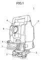
- An electronic survey instrument 1 mainly comprises a base unit 2 fixed on a tripod (not shown), a frame unit 3 rotatable around a vertical axis and mounted on the base unit 2, and a body tube 4 tiltable around a horizontal axis and mounted on the frame unit 3.
- Leveling screws 5 are provided on the base unit 2, and leveling operation of the electronic survey instrument 1 can be performed by adjusting the leveling screws 5.
- a control unit 10 (to be described later) is provided on the frame unit 3, and a display unit 6 and an operation/input unit 7 are further provided.
- a telescope 8 is mounted on the tube body 4, a telescope 8 is mounted.
- a vertical angle encoder 11 is mounted on a rotator of the body tube 4.
- a detection signal from the vertical angle encoder 11 is inputted to a vertical angle measuring unit 12.
- the vertical angle measuring unit 12 Based on the signal from the vertical angle encoder 11, the vertical angle measuring unit 12 calculates a tilt angle of the body tube 4, and the result of calculation is inputted to a control arithmetic unit 13.
- a horizontal angle encoder 14 is mounted on a rotator of the frame unit 3.
- a signal from the horizontal angle encoder 14 is inputted to a horizontal angle measuring unit 15.
- the horizontal angle measuring unit 15 counts or stores the signal from the horizontal angle encoder 14.
- the result is inputted to the control arithmetic unit 13, and a horizontal angle is calculated.
- the control arithmetic unit 13 calculates a measuring distance and a measuring angle and controls the electronic survey instrument 1 in operation such as display operation.
- a storage unit 19 connected to the control arithmetic unit 13 comprises semiconductor storage means such as ROM, RAM, flash ROM, etc. Measured values are stored, and a basic program and an application program are stored.
- the storage unit 19 is mounted in advance on a wiring substrate (not shown) of the control arithmetic unit 13.
- the control arithmetic unit 13 drives and controls a distance measuring light projecting unit 16.
- the distance measuring light projecting unit 16 projects a distance measuring light to an object 17.
- the distance measuring light thus projected is reflected by the object 17.
- the reflected distance measuring light is detected by a photodetection unit 18.
- a detection signal is inputted to the control arithmetic unit 13, and the distance is calculated.
- the display unit 6 and the operation/input unit 7 are connected to the control arithmetic unit 13.
- the object 17 is arranged at a predetermined position such as a known point, a measuring point, etc.
- Conditions for measurement, etc. are inputted by the operation/input unit 7, and the data thus inputted are displayed on the display unit 6.
- the control arithmetic unit 13 displays guidance information display such as information on a measuring procedure on the display unit 6. Following the guidance information display, a measuring operator inputs starting of measurement, and the measuring operation is started.
- the distance measuring light is projected from the distance measuring light projecting unit 16.
- the distance measuring light reflected by the object 17 is received by the photodetection unit 18.
- the result of the photodetection is inputted to the control arithmetic unit 13, and the distance to the object 17 is calculated.
- a vertical angle with respect to the object 17 is inputted to the control arithmetic unit 13 from the vertical angle measuring unit 12.
- a horizontal angle is also inputted to the control arithmetic unit 13 from the horizontal angle measuring unit 15.
- the distance measurement result, the vertical angle, and the horizontal angle are displayed on the display unit 6.
- process of measurement is displayed on the display unit 6.
- the display of the inputted data on the display unit 6, or the displays of the guidance information for measurement, the measurement result and the measurement process, etc. are performed in accordance with a program stored in advance in the storage unit 19.
- the present embodiment is provided with a function to rewrite the program stored in the storage unit 19.
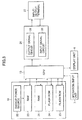
- the storage unit 19 comprises a first RAM 21, a second RAM 23, to which a backup power source 22 is connected, a flash ROM 24, and a flash ROM 25.
- the first RAM 21 is a storage means for temporarily storing the data, the program or the calculation result, etc. and the data are stored so far as power is connected.
- the second RAM 23 stores data such as setting values required for operating the electronic survey instrument 1, correction value necessary for calculation, etc. The stored data are maintained by the backup power source 22.
- the flash ROM 24 maintains the stored data without supply of power.
- the flash ROM 24 stores a copying program for copying survey data and for copying the program, a transfer program for transferring the copied data, or a writing program for writing the data transferred from outside to the flash ROM 25. These programs are not rewritable.
- the flash ROM 25 maintains the stored data without supply of power.
- the flash ROM 25 stores a basic control program necessary for operation of hardware in the electronic survey instrument 1, e.g. a program for calculating the vertical angle or the horizontal angle based on a signal from the vertical angle measuring unit 12 or the horizontal angle measuring unit 15, and a program for projecting the distance measuring light from the distance measuring light projecting unit 16, and for receiving the reflected light and for capturing the photodetection signal and for calculating the distance.
- a survey program e.g. a survey sequence program for automatically performing the survey operation, and a display program for displaying the survey result, and the process of survey in various modes on the display unit 6 are stored. These programs are rewritable for the purpose of updating the program version, or of repairing program bug.
- the flash ROM 25 is divided to the flash ROM for the basic program and the flash ROM for the application program.
- An input/output means 26 is connected to the control arithmetic unit 13.
- the input/output means 26 comprises an output signal processing circuit 28 for converting data such as the programs stored in the flash ROM 25 to a form of signal, which can be outputted to outside such as series of signals, and an input signal processing circuit 29 for converting the series of data inputted from outside to a form of signals to be processed at the control arithmetic unit 13.
- an input/output terminal 27 e.g. a 232C terminal
- an external device e.g. other electronic survey instrument
- the input/output terminal connected to the other electronic survey instrument and the copying program is incorporated, it is possible to connect to the other electronic survey instrument via the input/output terminal 27 and to transfer the data from one electronic survey instrument to the other electronic survey instrument.
- the copying program is started by the operation/input unit 7. Also, by the operation from the operation/input unit 7, an old program stored in the flash ROM 25 can be erased and a new program can be rewritten.
- the program can be transferred from the electronic survey instrument where a survey program of new version is stored to the other electronic survey instrument and the program can be rewritten.
- Step 01 The electronic survey instrument A is connected to the electronic survey instrument B via the input/output terminal 27 by a cable.
- the copy source and the copy destination are set by a selector switch, which is used to differentiate the copy source from the copy destination or by a selector switch, which validates only one of the transferred program and the rewritten program.
- the selector switch may be a mechanical switch or a software-oriented switch.
- Step 02 By starting the rewritten program of the electronic survey instrument B, the contents stored in the flash ROM 25 is erased, and it is turned to the rewrite standby status.
- Step 03 The copying program of the electronic survey instrument A is selected and started.
- Step 04 It is checked whether the electronic survey instrument B is ready for data input. If the result of the checking is acceptable (OK), the transfer program is automatically started, and the copying data is transferred to the electronic survey instrument B. If the result of the checking is not acceptable (NO), the copying is stopped. It is displayed on the display unit 6 whether the copying operation has been completed or not. To complete the copying operation, the procedure should be repeated from Step 01 again.
- Step 05 The survey program of the electronic survey instrument A is read.
- Step 06 The survey program thus read is temporarily stored in the first RAM 21.
- Step 07 The survey program of the first RAM 21 is converted to data for sequential delivery by the output signal processing circuit 28. The data are then outputted via the input/output terminal 27 and are transferred to the electronic survey instrument B. The data transferred via the input/output terminal 27 and the input signal processing circuit 29 of the electronic survey instrument B are incorporated, and the data are converted at the input signal processing circuit 29 and are written in the flash ROM 25.
- Step 08 It is checked whether the copying operation has been normally completed or not. If copying is not completed, the procedure is returned to Step 05, and copying operation is further continued. If copying has been normally completed, the completion of copying is displayed on the display unit 6 as soon as the copying program has been completed.
- the data are transferred via the cable, while it may be designed in such manner that a wireless transmitter/receiver is provided in the electronic survey instruments, and the data may be transmitted and received by wireless.
- the electronic survey instruments When the electronic survey instruments are connected with each other via the cable, it may be designed in such manner that a plurality of electronic survey instruments are connected in series so that survey programs of a plurality of electronic survey instruments can be rewritten at the same time.
- a wireless system if one survey instrument is assigned as the copy source survey instrument, a plurality of electronic survey instruments can receive the data at the same time. Then, it is possible to rewrite the survey programs of a plurality of electronic survey instruments at the same time. By repeating copying, programs of many electronic survey instruments can be rewritten easily.
- a measuring device comprises a program for operating the measuring device, a copying program for rewriting the program or for copying the program, a rewritable first storage means for storing the program, a signal input/output means, and a second storage means for storing the copying program, wherein the program stored in the first storage means is rewritten by a new program inputted through the signal input/output means.
Abstract
Description
- The present invention relates to a measuring device, which comprises functions to display or store measured values and further to display guidance information for operation.
- In recent years, a mechanical type survey instrument only for performing surveying operation at predetermined points has been used less frequently. Instead of this, an electronic survey instrument is becoming the main stream in this field. The electronic survey instrument is provided with special programs so that the electronic survey instrument can display or store measured values, so that it can display guidance information for operation to facilitate easily execution of a complicated surveying procedure or so that it can simplify the measuring procedure by inputting predetermined measuring conditions.
- The programs include a basic program and an application program. The basic program comprises a program for converting a signal from a distance measuring unit to a distance, a program for converting a signal from an encoder to an angle, and a program for displaying surveyed values on a display unit. The application program calculates or stores the measured values by a procedure according to the surveying operation. There are various types of the application programs depending on the type of surveying, and the application program is installed by electronic medium such as memory card or is stored in advance in a built-in storage unit.
- In a card type survey instrument, because the programs can be customized, it is often used in a total station, which is a high-grade electronic survey instrument.
- In a built-in type electronic survey instrument where a general surveying procedure is stored in advance, the basic program and the application program are recorded in a ROM mounted in a circuit substrate.
- Incidentally, unlike a simple mechanical type survey instrument, the electronic survey instrument is operated according to the programs. New functions can be added, program bug can be repaired, or version of the program can be updated.
- In the card type electronic survey instrument, the programs stored in a card may be rewritten for the purpose of repairing program bug or of updating the program version, etc. However, the basic program is incorporated in the survey instrument, and a cover of the instrument must be opened for the purpose of rewriting. In the electronic survey instrument with programs incorporated in it, both the application program and the basic program are incorporated in the instrument. When it is wanted to update the version of the program, a cover of a main unit must be opened, and ROM inserted in the circuit substrate must be replaced.
- When a program bug is repaired or the version of the program is updated, if it is a card type survey instrument, the procedure is simple and can be carried out at the distributors or at the survey companies which have a plenty of survey instruments. This can be carried out by replacing the memory card and by rewriting the contents of the memory card using a computer.
- However, as far as it is concerned with the incorporated components or in case of a built-in type electronic survey instrument, the cover of the main unit must be opened for such procedure. In recent years, program type survey instruments are becoming the main stream. In this respect, the program version must be updated more frequently. As described above, in case of the incorporated components or the built-in type survey instrument, such procedure can be dealt with by replacing storage components such as ROM. However, dust or dirt may be entrained and it requires complicated procedure. Also, replacing of expensive ROMs means higher cost. When it is necessary to perform this procedure on a great number of survey instruments, many ROM rewriting devices are required, and this is very difficult to accomplish.
- It is an object of the present invention to provide a measuring instrument, by which it is possible to easily rewrite the content of the program in an electronic survey instrument incorporated with survey programs, to simplify the operating procedure, and to reduce the cost.
- To attain the above object, the measuring device according to the present invention comprises a program for operating the measuring device, a copying program for rewriting the program or for copying the program, a rewritable first storage means for storing the program, a signal input/output means, and a second storage means for storing the copying program, wherein the program stored in the first storage means is rewritten through a new program inputted through the signal input/output means. Also, the present invention provides the measuring device as described above, wherein a program stored in the first storage means is copied by the copying program and is outputted through the signal input/output means. Further, the present invention provides the measuring device as described above, wherein the program can be rewritten from a measuring device to another measuring device by operating the copying program of the measuring device provided with the copying program. Also, the present invention provides the measuring device as described above, wherein a plurality of measuring devices can be connected via the signal input/output means, and by operating the copying program, the program stored in the first storage means of a measuring device on an input side can be rewritten by a new program stored in a measuring device on an output side. Further, the present invention provides the measuring device as described above, wherein the signal input/output means is provided with a wireless transmitter/receiver for inputting and outputting a data signal by wireless. Also, a measuring device, comprising a program for operating the measuring device, a copying program for rewriting the program or for copying the program, a rewritable first storage means for storing the program, a signal input/output means, and a second storage means for storing the copying program, wherein the second storage means further comprises a transfer program for inputting and outputting a program to be rewritten or a program to be copied as a data signal through the input/output means. Further, the present invention provides the measuring device as described above, wherein the program stored in the rewritable first storage means is a survey program, the measuring device has a distance measuring and angle measuring function, and the distance measuring and angle measuring function is performed based on the survey program.
Embodiments of the invention will now be described, by way of example, with reference to the drawings, of which: - Fig. 1 is an external view of an electronic survey instrument according to an embodiment of the present invention;
- Fig. 2 is a block diagram of the electronic survey instrument;
- Fig. 3 is a block diagram of a storage unit of the electronic survey instrument; and
- Fig. 4 is a flow chart to show copying operation of survey programs between the electronic survey instruments.
-
- Description will be given below on an embodiment of the present invention according to an electronic survey instrument referring to the drawings.
- First, description will be given on general features of the electronic survey instrument referring to Fig. 1.
- An
electronic survey instrument 1 mainly comprises abase unit 2 fixed on a tripod (not shown), aframe unit 3 rotatable around a vertical axis and mounted on thebase unit 2, and abody tube 4 tiltable around a horizontal axis and mounted on theframe unit 3. - Leveling
screws 5 are provided on thebase unit 2, and leveling operation of theelectronic survey instrument 1 can be performed by adjusting theleveling screws 5. A control unit 10 (to be described later) is provided on theframe unit 3, and adisplay unit 6 and an operation/input unit 7 are further provided. On thetube body 4, atelescope 8 is mounted. - Now, description will be given on the
control unit 10 referring to Fig. 2. - A
vertical angle encoder 11 is mounted on a rotator of thebody tube 4. A detection signal from thevertical angle encoder 11 is inputted to a verticalangle measuring unit 12. Based on the signal from thevertical angle encoder 11, the verticalangle measuring unit 12 calculates a tilt angle of thebody tube 4, and the result of calculation is inputted to a controlarithmetic unit 13. - A
horizontal angle encoder 14 is mounted on a rotator of theframe unit 3. A signal from thehorizontal angle encoder 14 is inputted to a horizontalangle measuring unit 15. The horizontalangle measuring unit 15 counts or stores the signal from thehorizontal angle encoder 14. The result is inputted to the controlarithmetic unit 13, and a horizontal angle is calculated. Based on a program, the controlarithmetic unit 13 calculates a measuring distance and a measuring angle and controls theelectronic survey instrument 1 in operation such as display operation. Astorage unit 19 connected to the controlarithmetic unit 13 comprises semiconductor storage means such as ROM, RAM, flash ROM, etc. Measured values are stored, and a basic program and an application program are stored. Thestorage unit 19 is mounted in advance on a wiring substrate (not shown) of the controlarithmetic unit 13. - The control
arithmetic unit 13 drives and controls a distance measuringlight projecting unit 16. The distance measuringlight projecting unit 16 projects a distance measuring light to anobject 17. The distance measuring light thus projected is reflected by theobject 17. The reflected distance measuring light is detected by aphotodetection unit 18. A detection signal is inputted to the controlarithmetic unit 13, and the distance is calculated. - The
display unit 6 and the operation/input unit 7 are connected to the controlarithmetic unit 13. - Description will be given below on measuring operation in the
electronic survey instrument 1. - The
object 17 is arranged at a predetermined position such as a known point, a measuring point, etc. Conditions for measurement, etc. are inputted by the operation/input unit 7, and the data thus inputted are displayed on thedisplay unit 6. Or, based on the conditions thus inputted, the controlarithmetic unit 13 displays guidance information display such as information on a measuring procedure on thedisplay unit 6. Following the guidance information display, a measuring operator inputs starting of measurement, and the measuring operation is started. - The distance measuring light is projected from the distance measuring
light projecting unit 16. The distance measuring light reflected by theobject 17 is received by thephotodetection unit 18. The result of the photodetection is inputted to the controlarithmetic unit 13, and the distance to theobject 17 is calculated. A vertical angle with respect to theobject 17 is inputted to the controlarithmetic unit 13 from the verticalangle measuring unit 12. In this case, a horizontal angle is also inputted to the controlarithmetic unit 13 from the horizontalangle measuring unit 15. - The distance measurement result, the vertical angle, and the horizontal angle are displayed on the
display unit 6. When necessary, process of measurement is displayed on thedisplay unit 6. - The display of the inputted data on the
display unit 6, or the displays of the guidance information for measurement, the measurement result and the measurement process, etc. are performed in accordance with a program stored in advance in thestorage unit 19. - The present embodiment is provided with a function to rewrite the program stored in the
storage unit 19. - Now, description will be given referring to Fig. 3.
- The
storage unit 19 comprises afirst RAM 21, asecond RAM 23, to which abackup power source 22 is connected, aflash ROM 24, and aflash ROM 25. - The
first RAM 21 is a storage means for temporarily storing the data, the program or the calculation result, etc. and the data are stored so far as power is connected. Thesecond RAM 23 stores data such as setting values required for operating theelectronic survey instrument 1, correction value necessary for calculation, etc. The stored data are maintained by thebackup power source 22. - The
flash ROM 24 maintains the stored data without supply of power. Theflash ROM 24 stores a copying program for copying survey data and for copying the program, a transfer program for transferring the copied data, or a writing program for writing the data transferred from outside to theflash ROM 25. These programs are not rewritable. - The
flash ROM 25 maintains the stored data without supply of power. Theflash ROM 25 stores a basic control program necessary for operation of hardware in theelectronic survey instrument 1, e.g. a program for calculating the vertical angle or the horizontal angle based on a signal from the verticalangle measuring unit 12 or the horizontalangle measuring unit 15, and a program for projecting the distance measuring light from the distance measuringlight projecting unit 16, and for receiving the reflected light and for capturing the photodetection signal and for calculating the distance. Also, a survey program, e.g. a survey sequence program for automatically performing the survey operation, and a display program for displaying the survey result, and the process of survey in various modes on thedisplay unit 6 are stored. These programs are rewritable for the purpose of updating the program version, or of repairing program bug. In most cases, theflash ROM 25 is divided to the flash ROM for the basic program and the flash ROM for the application program. - An input/output means 26 is connected to the control
arithmetic unit 13. The input/output means 26 comprises an outputsignal processing circuit 28 for converting data such as the programs stored in theflash ROM 25 to a form of signal, which can be outputted to outside such as series of signals, and an inputsignal processing circuit 29 for converting the series of data inputted from outside to a form of signals to be processed at the controlarithmetic unit 13. - To the input/output means 26, an input/
output terminal 27, e.g. a 232C terminal, is connected, and an external device, e.g. other electronic survey instrument, can be connected via the input/output terminal 27. - Because there is provided the input/output terminal connected to the other electronic survey instrument and the copying program is incorporated, it is possible to connect to the other electronic survey instrument via the input/
output terminal 27 and to transfer the data from one electronic survey instrument to the other electronic survey instrument. The copying program is started by the operation/input unit 7. Also, by the operation from the operation/input unit 7, an old program stored in theflash ROM 25 can be erased and a new program can be rewritten. - In so doing, even when there is no ROM rewriting device, the program can be transferred from the electronic survey instrument where a survey program of new version is stored to the other electronic survey instrument and the program can be rewritten.
- Also, it is possible to rewrite the stored survey program without replacing the
flash ROM 25 in the electronic survey instrument. - Referring to Fig. 4, description will be given now on copying of a survey program from an electronic survey instrument to another electronic survey instrument. Here, it is supposed that a copy source electronic survey instrument is A, and a copy destination electronic survey instrument is B.
- Step 01: The electronic survey instrument A is connected to the electronic survey instrument B via the input/
output terminal 27 by a cable. When copying is made between the electronic survey instruments each other, for the purpose of preventing rewriting of a survey program of new version to a survey program of old version, the copy source and the copy destination are set by a selector switch, which is used to differentiate the copy source from the copy destination or by a selector switch, which validates only one of the transferred program and the rewritten program. The selector switch may be a mechanical switch or a software-oriented switch. - Step 02: By starting the rewritten program of the electronic survey instrument B, the contents stored in the
flash ROM 25 is erased, and it is turned to the rewrite standby status. - Step 03: The copying program of the electronic survey instrument A is selected and started.
- Step 04: It is checked whether the electronic survey instrument B is ready for data input. If the result of the checking is acceptable (OK), the transfer program is automatically started, and the copying data is transferred to the electronic survey instrument B. If the result of the checking is not acceptable (NO), the copying is stopped. It is displayed on the
display unit 6 whether the copying operation has been completed or not. To complete the copying operation, the procedure should be repeated from Step 01 again. - Step 05: The survey program of the electronic survey instrument A is read.
- Step 06: The survey program thus read is temporarily stored in the
first RAM 21. - Step 07: The survey program of the
first RAM 21 is converted to data for sequential delivery by the outputsignal processing circuit 28. The data are then outputted via the input/output terminal 27 and are transferred to the electronic survey instrument B. The data transferred via the input/output terminal 27 and the inputsignal processing circuit 29 of the electronic survey instrument B are incorporated, and the data are converted at the inputsignal processing circuit 29 and are written in theflash ROM 25. - Step 08: It is checked whether the copying operation has been normally completed or not. If copying is not completed, the procedure is returned to Step 05, and copying operation is further continued. If copying has been normally completed, the completion of copying is displayed on the
display unit 6 as soon as the copying program has been completed. - In the above embodiment, the data are transferred via the cable, while it may be designed in such manner that a wireless transmitter/receiver is provided in the electronic survey instruments, and the data may be transmitted and received by wireless.
- When the electronic survey instruments are connected with each other via the cable, it may be designed in such manner that a plurality of electronic survey instruments are connected in series so that survey programs of a plurality of electronic survey instruments can be rewritten at the same time. In case of a wireless system, if one survey instrument is assigned as the copy source survey instrument, a plurality of electronic survey instruments can receive the data at the same time. Then, it is possible to rewrite the survey programs of a plurality of electronic survey instruments at the same time. By repeating copying, programs of many electronic survey instruments can be rewritten easily.
- In the above, description has been given on the electronic survey instrument. Programs can be rewritten easily in similar manner so far as it is a measuring device provided with programs and operated according to such programs.
- According to the present invention, a measuring device comprises a program for operating the measuring device, a copying program for rewriting the program or for copying the program, a rewritable first storage means for storing the program, a signal input/output means, and a second storage means for storing the copying program, wherein the program stored in the first storage means is rewritten by a new program inputted through the signal input/output means. Thus, without replacing the storage unit such as ROM in the electronic survey instrument, it is possible to easily rewrite the contents of the stored program. This contributes to the simplification of operating procedure and to the reduction of cost.
Claims (10)
- A measuring device, comprising a program for operating the measuring device, a copying program for rewriting said program or for copying said program, a rewritable first storage means for storing said program, a signal input/output means, and a second storage means for storing said copying program, wherein said program stored in said first storage means is rewritten by a new program inputted through said signal input/output means.
- A measuring device according to claim 1, wherein a program stored in said first storage means is copied by the copying program and is outputted through said signal input/output means.
- A measuring device according to claim 1, wherein the program can be rewritten from a measuring device to another measuring devices by operating said copying program of the measuring device provided with said copying program.
- A measuring device according to claim 1, wherein a plurality of measuring devices can be connected via said signal input/output means, and by operating said copying program, said program stored in said first storage means of a measuring device on an input side can be rewritten by a new program stored in a measuring device on an output side.
- A measuring device according to claim 1, wherein said signal input/output means is provided with a wireless transmitter/receiver for inputting and outputting a data signal by wireless.
- A measuring device, comprising a program for operating the measuring device, a copying program for rewriting said program or for copying said program, a rewritable first storage means for storing said program, a signal input/output means, and a second storage means for storing said copying program, wherein said second storage means further comprises a transfer program for inputting and outputting a program to be rewritten or a program to be copied as a data signal through said input/output means.
- A measuring device according to one of claims 1 to 5, wherein said program stored in said rewritable first storage means is a survey program, the measuring device has a distance measuring and angle measuring function, and said distance measuring and angle measuring function is performed based on said survey program.
- A measuring device, comprising a program for operating the measuring device, a rewriteable first storage means for storing said program and a signal input/output means, wherein said program stored in first storage means is rewriteable by a new program inputted through said signal input/output means.
- A method of re-writing a program for operating a measure device wherein the program is stored in a rewriteable first storage means, in which a new program is inputted through a signal input/output means and the operating program is rewritten by the new program.
- A method of re-writing a program for operating a measure device wherein the program is stored in a rewriteable first storage means, and a copying program for rewriting said program or for copying said program is stored in a second storage means, in which a transfer program inputs or outputs a program to be rewritten or a program to be copied as a data signal through said input/output means.
Applications Claiming Priority (2)
| Application Number | Priority Date | Filing Date | Title |
|---|---|---|---|
| JP2001208088A JP2003022191A (en) | 2001-07-09 | 2001-07-09 | Measurement equipment |
| JP2001208088 | 2001-07-09 |
Publications (3)
| Publication Number | Publication Date |
|---|---|
| EP1275932A2 true EP1275932A2 (en) | 2003-01-15 |
| EP1275932A3 EP1275932A3 (en) | 2003-07-30 |
| EP1275932B1 EP1275932B1 (en) | 2010-03-17 |
Family
ID=19043970
Family Applications (1)
| Application Number | Title | Priority Date | Filing Date |
|---|---|---|---|
| EP02254711A Expired - Lifetime EP1275932B1 (en) | 2001-07-09 | 2002-07-04 | Program updating in a measuring device |
Country Status (4)
| Country | Link |
|---|---|
| US (1) | US6799142B2 (en) |
| EP (1) | EP1275932B1 (en) |
| JP (1) | JP2003022191A (en) |
| DE (1) | DE60235678D1 (en) |
Families Citing this family (4)
| Publication number | Priority date | Publication date | Assignee | Title |
|---|---|---|---|---|
| WO2005124625A1 (en) * | 2004-06-12 | 2005-12-29 | Hazy James K | System and method to simulate the impact of leadership activity |
| JP2006038581A (en) * | 2004-07-26 | 2006-02-09 | Topcon Corp | Management system of surveying system |
| US8539685B2 (en) | 2011-01-20 | 2013-09-24 | Trimble Navigation Limited | Integrated surveying and leveling |
| WO2016154633A1 (en) * | 2015-03-26 | 2016-09-29 | Boston Scientific Scimed, Inc. | Systems and methods for vascular occlusion |
Citations (6)
| Publication number | Priority date | Publication date | Assignee | Title |
|---|---|---|---|---|
| JPH0996530A (en) * | 1995-09-29 | 1997-04-08 | Matsushita Electric Ind Co Ltd | Vehicle-mounted navigation device |
| EP0793166A2 (en) * | 1995-08-14 | 1997-09-03 | Aisin Aw Co., Ltd. | Navigation system and computer program loading therefor |
| US5806015A (en) * | 1997-07-22 | 1998-09-08 | Mitsubishi Denki Kabushiki Kaisha | Automotive controller |
| US6034722A (en) * | 1997-11-03 | 2000-03-07 | Trimble Navigation Limited | Remote control and viewing for a total station |
| US6081755A (en) * | 1997-07-24 | 2000-06-27 | Mitsubishi Denki Kabushiki Kaisha | Vehicle control device |
| JP2001005671A (en) * | 1999-06-23 | 2001-01-12 | Denso Corp | Data transmission system |
Family Cites Families (8)
| Publication number | Priority date | Publication date | Assignee | Title |
|---|---|---|---|---|
| US5752040A (en) * | 1991-09-30 | 1998-05-12 | Canon Kabushiki Kaisha | Image processing apparatus which can update program |
| JPH08285577A (en) * | 1995-04-19 | 1996-11-01 | Asahi Optical Co Ltd | Total station |
| JPH1010931A (en) * | 1996-06-27 | 1998-01-16 | Sharp Corp | Image forming device |
| US6275911B1 (en) * | 1996-09-20 | 2001-08-14 | Denso Corporation | Memory writing device for an electronic device |
| JPH10269074A (en) * | 1997-03-25 | 1998-10-09 | Zaou Nikon:Kk | Surveying machine, method for installing program to surveying machine, and method for assembling surveying machine |
| JP2000267857A (en) * | 1999-03-17 | 2000-09-29 | Oki Data Corp | Facsimile maintenance system |
| JP3545659B2 (en) * | 1999-10-21 | 2004-07-21 | 松下電器産業株式会社 | Program updating method and communication terminal device |
| JP2001209543A (en) * | 2000-01-28 | 2001-08-03 | Nec Ic Microcomput Syst Ltd | Program rewriting method for flash microcomputer |
-
2001
- 2001-07-09 JP JP2001208088A patent/JP2003022191A/en active Pending
-
2002
- 2002-06-26 US US10/180,263 patent/US6799142B2/en not_active Expired - Lifetime
- 2002-07-04 EP EP02254711A patent/EP1275932B1/en not_active Expired - Lifetime
- 2002-07-04 DE DE60235678T patent/DE60235678D1/en not_active Expired - Lifetime
Patent Citations (6)
| Publication number | Priority date | Publication date | Assignee | Title |
|---|---|---|---|---|
| EP0793166A2 (en) * | 1995-08-14 | 1997-09-03 | Aisin Aw Co., Ltd. | Navigation system and computer program loading therefor |
| JPH0996530A (en) * | 1995-09-29 | 1997-04-08 | Matsushita Electric Ind Co Ltd | Vehicle-mounted navigation device |
| US5806015A (en) * | 1997-07-22 | 1998-09-08 | Mitsubishi Denki Kabushiki Kaisha | Automotive controller |
| US6081755A (en) * | 1997-07-24 | 2000-06-27 | Mitsubishi Denki Kabushiki Kaisha | Vehicle control device |
| US6034722A (en) * | 1997-11-03 | 2000-03-07 | Trimble Navigation Limited | Remote control and viewing for a total station |
| JP2001005671A (en) * | 1999-06-23 | 2001-01-12 | Denso Corp | Data transmission system |
Non-Patent Citations (2)
| Title |
|---|
| PATENT ABSTRACTS OF JAPAN vol. 1997, no. 08, 29 August 1997 (1997-08-29) & JP 09 096530 A (MATSUSHITA ELECTRIC IND CO LTD), 8 April 1997 (1997-04-08) * |
| PATENT ABSTRACTS OF JAPAN vol. 2000, no. 16, 8 May 2001 (2001-05-08) & JP 2001 005671 A (DENSO CORP), 12 January 2001 (2001-01-12) * |
Also Published As
| Publication number | Publication date |
|---|---|
| EP1275932B1 (en) | 2010-03-17 |
| DE60235678D1 (en) | 2010-04-29 |
| JP2003022191A (en) | 2003-01-24 |
| US6799142B2 (en) | 2004-09-28 |
| EP1275932A3 (en) | 2003-07-30 |
| US20030009310A1 (en) | 2003-01-09 |
Similar Documents
| Publication | Publication Date | Title |
|---|---|---|
| US7339611B2 (en) | Method and arrangement for carrying out an information flow and data flow for geodetic instruments | |
| EP2098820B1 (en) | Geographical data collecting device | |
| JP4434818B2 (en) | Error correction method for portable communication terminal and its geomagnetic sensor | |
| US6081204A (en) | Automated communication of electricity meter data | |
| EP0650125A1 (en) | Handy computer with built-in digital camera and spot state recording method using the same | |
| JP2006292522A (en) | Route guidance system | |
| KR20060031685A (en) | Image projector, inclination angle detection method, and projection image correction method | |
| CN102137183A (en) | Mobile communication terminal and method | |
| JP2020008423A (en) | Construction management system | |
| US6799142B2 (en) | Measuring device | |
| JP4213072B2 (en) | Error correction method for portable communication terminal and its geomagnetic sensor | |
| CN109154500A (en) | Laser leveling inspection | |
| JP2007170978A (en) | Survey machine and remote management system of the survey machine | |
| JP2005275327A (en) | Projection display device | |
| GB2229822A (en) | Surveying apparatus | |
| JP4213071B2 (en) | Error correction method for portable communication terminal and its geomagnetic sensor | |
| JP4093982B2 (en) | Error correction method for portable communication terminal and its geomagnetic sensor | |
| KR101946538B1 (en) | Facility property information update system using mobile smart device | |
| JP2919273B2 (en) | Multifunctional surveying measurement system | |
| KR20010070343A (en) | multi ROM writer and the control method thereof | |
| KR100800411B1 (en) | Apparatus and method for controlling buffer memory in digital video recorder | |
| KR100643406B1 (en) | An apparatus for automatically compensing a key-ston in a projector | |
| KR20040022020A (en) | Display device and method for upgrading firmware remotely | |
| US20080051914A1 (en) | Display apparatus and information update method therefor | |
| JPS585609A (en) | Video signal analyzing device and method for digging tunnel by utilizing said device |
Legal Events
| Date | Code | Title | Description |
|---|---|---|---|
| PUAI | Public reference made under article 153(3) epc to a published international application that has entered the european phase |
Free format text: ORIGINAL CODE: 0009012 |
|
| AK | Designated contracting states |
Kind code of ref document: A2 Designated state(s): AT BE BG CH CY CZ DE DK EE ES FI FR GB GR IE IT LI LU MC NL PT SE SK TR |
|
| AX | Request for extension of the european patent |
Free format text: AL;LT;LV;MK;RO;SI |
|
| PUAL | Search report despatched |
Free format text: ORIGINAL CODE: 0009013 |
|
| AK | Designated contracting states |
Designated state(s): AT BE BG CH CY CZ DE DK EE ES FI FR GB GR IE IT LI LU MC NL PT SE SK TR |
|
| AX | Request for extension of the european patent |
Extension state: AL LT LV MK RO SI |
|
| RIC1 | Information provided on ipc code assigned before grant |
Ipc: 7G 06F 13/00 B Ipc: 7G 06F 9/445 B Ipc: 7G 01C 15/00 A |
|
| 17P | Request for examination filed |
Effective date: 20031023 |
|
| AKX | Designation fees paid |
Designated state(s): CH DE LI SE |
|
| 17Q | First examination report despatched |
Effective date: 20061115 |
|
| GRAP | Despatch of communication of intention to grant a patent |
Free format text: ORIGINAL CODE: EPIDOSNIGR1 |
|
| GRAS | Grant fee paid |
Free format text: ORIGINAL CODE: EPIDOSNIGR3 |
|
| GRAA | (expected) grant |
Free format text: ORIGINAL CODE: 0009210 |
|
| AK | Designated contracting states |
Kind code of ref document: B1 Designated state(s): CH DE LI SE |
|
| REG | Reference to a national code |
Ref country code: CH Ref legal event code: NV Representative=s name: KIRKER & CIE S.A. Ref country code: CH Ref legal event code: EP |
|
| REF | Corresponds to: |
Ref document number: 60235678 Country of ref document: DE Date of ref document: 20100429 Kind code of ref document: P |
|
| REG | Reference to a national code |
Ref country code: SE Ref legal event code: TRGR |
|
| PLBE | No opposition filed within time limit |
Free format text: ORIGINAL CODE: 0009261 |
|
| STAA | Information on the status of an ep patent application or granted ep patent |
Free format text: STATUS: NO OPPOSITION FILED WITHIN TIME LIMIT |
|
| 26N | No opposition filed |
Effective date: 20101220 |
|
| PGFP | Annual fee paid to national office [announced via postgrant information from national office to epo] |
Ref country code: SE Payment date: 20150713 Year of fee payment: 14 |
|
| REG | Reference to a national code |
Ref country code: SE Ref legal event code: EUG |
|
| PG25 | Lapsed in a contracting state [announced via postgrant information from national office to epo] |
Ref country code: SE Free format text: LAPSE BECAUSE OF NON-PAYMENT OF DUE FEES Effective date: 20160705 |
|
| PGFP | Annual fee paid to national office [announced via postgrant information from national office to epo] |
Ref country code: DE Payment date: 20180619 Year of fee payment: 17 |
|
| PGFP | Annual fee paid to national office [announced via postgrant information from national office to epo] |
Ref country code: CH Payment date: 20180713 Year of fee payment: 17 |
|
| REG | Reference to a national code |
Ref country code: DE Ref legal event code: R119 Ref document number: 60235678 Country of ref document: DE |
|
| REG | Reference to a national code |
Ref country code: CH Ref legal event code: PL |
|
| PG25 | Lapsed in a contracting state [announced via postgrant information from national office to epo] |
Ref country code: DE Free format text: LAPSE BECAUSE OF NON-PAYMENT OF DUE FEES Effective date: 20200201 |
|
| PG25 | Lapsed in a contracting state [announced via postgrant information from national office to epo] |
Ref country code: LI Free format text: LAPSE BECAUSE OF NON-PAYMENT OF DUE FEES Effective date: 20190731 Ref country code: CH Free format text: LAPSE BECAUSE OF NON-PAYMENT OF DUE FEES Effective date: 20190731 |