EP1273831A2 - Eingangswellenbremssteuerung zum Synchronisieren eines Getriebehalbautomaten - Google Patents
Eingangswellenbremssteuerung zum Synchronisieren eines Getriebehalbautomaten Download PDFInfo
- Publication number
- EP1273831A2 EP1273831A2 EP02015085A EP02015085A EP1273831A2 EP 1273831 A2 EP1273831 A2 EP 1273831A2 EP 02015085 A EP02015085 A EP 02015085A EP 02015085 A EP02015085 A EP 02015085A EP 1273831 A2 EP1273831 A2 EP 1273831A2
- Authority
- EP
- European Patent Office
- Prior art keywords
- speed
- clutch
- transmission
- rotation
- rotation matching
- Prior art date
- Legal status (The legal status is an assumption and is not a legal conclusion. Google has not performed a legal analysis and makes no representation as to the accuracy of the status listed.)
- Withdrawn
Links
Images

Classifications
-
- F—MECHANICAL ENGINEERING; LIGHTING; HEATING; WEAPONS; BLASTING
- F16—ENGINEERING ELEMENTS AND UNITS; GENERAL MEASURES FOR PRODUCING AND MAINTAINING EFFECTIVE FUNCTIONING OF MACHINES OR INSTALLATIONS; THERMAL INSULATION IN GENERAL
- F16H—GEARING
- F16H61/00—Control functions within control units of change-speed- or reversing-gearings for conveying rotary motion ; Control of exclusively fluid gearing, friction gearing, gearings with endless flexible members or other particular types of gearing
- F16H61/04—Smoothing ratio shift
- F16H61/0403—Synchronisation before shifting
-
- F—MECHANICAL ENGINEERING; LIGHTING; HEATING; WEAPONS; BLASTING
- F16—ENGINEERING ELEMENTS AND UNITS; GENERAL MEASURES FOR PRODUCING AND MAINTAINING EFFECTIVE FUNCTIONING OF MACHINES OR INSTALLATIONS; THERMAL INSULATION IN GENERAL
- F16H—GEARING
- F16H3/00—Toothed gearings for conveying rotary motion with variable gear ratio or for reversing rotary motion
- F16H3/02—Toothed gearings for conveying rotary motion with variable gear ratio or for reversing rotary motion without gears having orbital motion
- F16H3/08—Toothed gearings for conveying rotary motion with variable gear ratio or for reversing rotary motion without gears having orbital motion exclusively or essentially with continuously meshing gears, that can be disengaged from their shafts
- F16H3/12—Toothed gearings for conveying rotary motion with variable gear ratio or for reversing rotary motion without gears having orbital motion exclusively or essentially with continuously meshing gears, that can be disengaged from their shafts with means for synchronisation not incorporated in the clutches
-
- F—MECHANICAL ENGINEERING; LIGHTING; HEATING; WEAPONS; BLASTING
- F16—ENGINEERING ELEMENTS AND UNITS; GENERAL MEASURES FOR PRODUCING AND MAINTAINING EFFECTIVE FUNCTIONING OF MACHINES OR INSTALLATIONS; THERMAL INSULATION IN GENERAL
- F16H—GEARING
- F16H63/00—Control outputs from the control unit to change-speed- or reversing-gearings for conveying rotary motion or to other devices than the final output mechanism
- F16H63/02—Final output mechanisms therefor; Actuating means for the final output mechanisms
- F16H63/30—Constructional features of the final output mechanisms
- F16H63/34—Locking or disabling mechanisms
- F16H63/3416—Parking lock mechanisms or brakes in the transmission
- F16H63/345—Parking lock mechanisms or brakes in the transmission using friction brakes, e.g. a band brakes
-
- F—MECHANICAL ENGINEERING; LIGHTING; HEATING; WEAPONS; BLASTING
- F16—ENGINEERING ELEMENTS AND UNITS; GENERAL MEASURES FOR PRODUCING AND MAINTAINING EFFECTIVE FUNCTIONING OF MACHINES OR INSTALLATIONS; THERMAL INSULATION IN GENERAL
- F16H—GEARING
- F16H61/00—Control functions within control units of change-speed- or reversing-gearings for conveying rotary motion ; Control of exclusively fluid gearing, friction gearing, gearings with endless flexible members or other particular types of gearing
- F16H61/04—Smoothing ratio shift
- F16H61/0403—Synchronisation before shifting
- F16H2061/0411—Synchronisation before shifting by control of shaft brakes
-
- F—MECHANICAL ENGINEERING; LIGHTING; HEATING; WEAPONS; BLASTING
- F16—ENGINEERING ELEMENTS AND UNITS; GENERAL MEASURES FOR PRODUCING AND MAINTAINING EFFECTIVE FUNCTIONING OF MACHINES OR INSTALLATIONS; THERMAL INSULATION IN GENERAL
- F16H—GEARING
- F16H63/00—Control outputs from the control unit to change-speed- or reversing-gearings for conveying rotary motion or to other devices than the final output mechanism
- F16H63/02—Final output mechanisms therefor; Actuating means for the final output mechanisms
- F16H63/30—Constructional features of the final output mechanisms
- F16H63/3023—Constructional features of the final output mechanisms the final output mechanisms comprising elements moved by fluid pressure
- F16H63/3026—Constructional features of the final output mechanisms the final output mechanisms comprising elements moved by fluid pressure comprising friction clutches or brakes
- F16H2063/3033—Constructional features of the final output mechanisms the final output mechanisms comprising elements moved by fluid pressure comprising friction clutches or brakes the brake is actuated by springs and released by a fluid pressure
-
- F—MECHANICAL ENGINEERING; LIGHTING; HEATING; WEAPONS; BLASTING
- F16—ENGINEERING ELEMENTS AND UNITS; GENERAL MEASURES FOR PRODUCING AND MAINTAINING EFFECTIVE FUNCTIONING OF MACHINES OR INSTALLATIONS; THERMAL INSULATION IN GENERAL
- F16H—GEARING
- F16H2200/00—Transmissions for multiple ratios
- F16H2200/003—Transmissions for multiple ratios characterised by the number of forward speeds
- F16H2200/0052—Transmissions for multiple ratios characterised by the number of forward speeds the gear ratios comprising six forward speeds
-
- F—MECHANICAL ENGINEERING; LIGHTING; HEATING; WEAPONS; BLASTING
- F16—ENGINEERING ELEMENTS AND UNITS; GENERAL MEASURES FOR PRODUCING AND MAINTAINING EFFECTIVE FUNCTIONING OF MACHINES OR INSTALLATIONS; THERMAL INSULATION IN GENERAL
- F16H—GEARING
- F16H3/00—Toothed gearings for conveying rotary motion with variable gear ratio or for reversing rotary motion
- F16H3/02—Toothed gearings for conveying rotary motion with variable gear ratio or for reversing rotary motion without gears having orbital motion
- F16H3/08—Toothed gearings for conveying rotary motion with variable gear ratio or for reversing rotary motion without gears having orbital motion exclusively or essentially with continuously meshing gears, that can be disengaged from their shafts
- F16H3/087—Toothed gearings for conveying rotary motion with variable gear ratio or for reversing rotary motion without gears having orbital motion exclusively or essentially with continuously meshing gears, that can be disengaged from their shafts characterised by the disposition of the gears
- F16H3/091—Toothed gearings for conveying rotary motion with variable gear ratio or for reversing rotary motion without gears having orbital motion exclusively or essentially with continuously meshing gears, that can be disengaged from their shafts characterised by the disposition of the gears including a single countershaft
- F16H3/0915—Toothed gearings for conveying rotary motion with variable gear ratio or for reversing rotary motion without gears having orbital motion exclusively or essentially with continuously meshing gears, that can be disengaged from their shafts characterised by the disposition of the gears including a single countershaft with coaxial input and output shafts
Definitions
- the present invention relates to an automatic clutch type transmission which comprises a speed-change clutch that engages or disengages the driving force of the engine, a transmission which is connected to the speed-change clutch so as to transmit [the abovementioned driving force], a shift lever which is used to change the gears of the transmission, and a control device which automatically engages and disengages the speed-change clutch as a result of the operation of the shift lever; more particularly, the present invention relates to a rotation matching mechanism for an automatic clutch type transmission which is used to synchronize the gears of the transmission in the case of up-shifting.
- Automatic clutch type transmissions include transmissions that are equipped with a speed-change clutch consisting of a wet type multi-plate clutch which is connected to the output shaft of the engine mounted in the vehicle via a fluid coupling (including torque converters), and which engages and disengages the driving force of the engine, a transmission which is connected to the speed-change clutch so as to transmit the abovementioned driving force, a shift lever which is used to change the gears of the transmission, and a control device which automatically engages and disengages the speed-change clutch as a result of the operation of the shift lever.
- a speed-change clutch consisting of a wet type multi-plate clutch which is connected to the output shaft of the engine mounted in the vehicle via a fluid coupling (including torque converters), and which engages and disengages the driving force of the engine
- a transmission which is connected to the speed-change clutch so as to transmit the abovementioned driving force
- a shift lever which is used to change the gears of the transmission
- a control device which automatically engage
- the driving force of the engine during operation is transmitted to the input shaft of the transmission via a fluid coupling and the speed-change clutch, and this driving force is transmitted from the input shaft to a hub via a countershaft, a counter gear disposed on this countershaft, a main gear that engages with this counter gear, a dog that rotates integrally with the main gear, and a sleeve that is spline-engaged with this dog, so that the driving force is transmitted to the output shaft of the hub.
- the speed-change clutch is disengaged, and the spline-engaged sleeve is moved so that the dog of the current speed and the hub are separated.
- the sleeve of this speed is engaged with the dog, and the speed-change clutch is engaged.
- a rotation matching mechanism (braking device) is installed on the countershaft in order to synchronize the rotation of the hub and the rotation of the dog to which a shift is being made when the gears are changed on the basis of the operation of the shift lever.
- the rotation of the countershaft is inhibited, and the rotation of the dog of the main gear speed to which a shift is being made is matched with the rotation of the hub that is to be connected, after which the sleeve on the side of this hub is engaged with the dog.
- the diameter of the input counter gear on the side of the countershaft is larger than that of the main gear on the side of the input shaft that transmits the driving force from the input shaft to the countershaft, so that the rotation is transmitted from the input shaft to the countershaft at a speed reduced by a factor of approximately 1.8. Accordingly, in cases where a gear rotation matching function is provided by installing a braking device on the countershaft, the size of the braking device is increased so that a large space is required.
- the braking device consists of a friction plate that is disposed on the rotating side and a pressing plate that is disposed on the fixed side, and a braking force is generated by the pressing contact of these plates with each other.
- the braking device is installed in a gear box in which the counter gears, dogs, hubs and the like of the transmission are accommodated; as a result, the braking device is exposed to lubricating oil inside this gear box, so that the friction characteristic is poor.
- the invention of claim 1 is a rotation matching mechanism for an automatic clutch type transmission comprising a speed-change clutch which engages or disengages the driving force of the engine, a transmission which is connected to the speed-change clutch so as to transmit the abovementioned driving force, a shift lever which is used to change the gears of the transmission, and a control device which automatically engages and disengages the speed-change clutch as a result of the operation of the shift lever, wherein a rotation matching braking device that reduces the speed of rotation of the input shaft of the transmission during up-shifting and thus synchronizes the gear to which the shift is being made is disposed on the input shaft of the transmission.
- the invention of claim 2 is the rotation matching mechanism for an automatic clutch type transmission according to claim 1, wherein the rotation matching braking device comprises a friction plate which rotates together with the input shaft of the abovementioned transmission, a pressing plate which is disposed on the side of the clutch housing so that this pressing plate can move toward or away from the abovemeritioned friction plate, and a pushing piston which is disposed on the housing side of the abovementioned transmission so that this pushing piston presses the friction plate and pressing plate against each other.
- the invention of claim 3 is the rotation matching mechanism for an automatic clutch type transmission according to claim 2, wherein the operation of the abovementioned pushing piston is performed by a control mechanism comprising a fluid pipe channel which is used to supply and discharge piston fluid pressure, an electromagnetic valve which supplies a fluid to the pipe channel and discharges this fluid from the pipe channel, and a control device which controls the ON/OFF operation of the abovementioned electromagnetic valve, and wherein the abovementioned control device performs ON/OFF control on the basis of the vehicle speed and the gear to which a shift is to be made.
- a control mechanism comprising a fluid pipe channel which is used to supply and discharge piston fluid pressure, an electromagnetic valve which supplies a fluid to the pipe channel and discharges this fluid from the pipe channel, and a control device which controls the ON/OFF operation of the abovementioned electromagnetic valve, and wherein the abovementioned control device performs ON/OFF control on the basis of the vehicle speed and the gear to which a shift is to be made.
- the invention of claim 4 is the rotation matching mechanism for an automatic clutch type transmission according to any of claims 1 through 3, wherein the abovementioned rotation matching braking device is disposed inside the same housing as the abovementioned speed-change clutch, and is controlled using the same fluid.
- the invention of claim 5 is the rotation matching mechanism for an automatic clutch type transmission according to claim 2, wherein the abovementioned rotation matching braking device is also used as a gear parking brake.
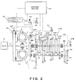
- a transmission T/M is connected to an engine E via a clutch mechanism 1.
- the clutch mechanism 1 consists of a fluid coupling 2 and a wet type multi-plate clutch (speed-change clutch) 3.
- the fluid coupling 2 is disposed at an intermediate point in the power transmission path that extends from the engine E to the transmission T/M, on the upstream side of this power transmission path, and the wet type multi-plate clutch 3 is disposed in series on the downstream side of the same power transmission path.
- the term "fluid coupling” used here has a broad meaning that includes torque converters, and a torque converter is also actually used in the present embodiment.
- the fluid coupling 2 comprises a pump part 4 which rotates integrally with a casing 18 that is connected to the output shaft (crankshaft) 1a of the engine E, a turbine part 5 which is caused to face the pump part 4 inside the casing 18, and which is connected to the input side of the clutch 3, and a stator part 6 which is interposed between the turbine part 5 and the pump part 4. Furthermore, this fluid coupling 2 has a lock-up device 20 consisting of a lock-up clutch 7 which couples and separates the pump part 4 and turbine part 5, and a hydraulic circuit 19 that operates this lock-up clutch 7.
- the input side of the wet type multi-plate clutch 3 is connected to the turbine part 5 via an input shaft 3a, and the output side is connected to the input shaft 8 of the transmission T/M so that this clutch engages and disengages the fluid coupling 2 and transmission T/M.
- this clutch is driven in the disengaging direction by a spring (not shown in the figures), and is engaged by hydraulic pressure from the hydraulic circuit 19.
- the transmission T/M has an input shaft 8, an output shaft 9 which is disposed coaxially with this input shaft 8, and a countershaft 10 which is disposed parallel to these other shafts.
- An input main gear 11 is provided on the input shaft 8.
- a first-speed main gear M1, second-speed main gear M2, third-speed main gear M3, fourth-speed main gear M4 and reverse main gear MR are respectively shaft-supported on the output shaft 9, and a sixth-speed main gear M6 is fastened to the output shaft 9.
- An input counter gear 12 which engages with the input main gear 11, a first-speed counter gear C1 which engages with the first-speed main gear M1, a second-speed counter gear C2 which engages with the second-speed main gear M2, a third-speed counter gear C3 which engages with the third-speed main gear M3, a fourth-speed counter gear C4 which engages with the fourth-speed main gear M4, and a reverse counter gear CR which engages with the reverse main gear MR via an idle gear IR, are fastened to the countershaft 10, and a sixth-speed counter gear C6 which engages with the sixth-speed main gear M6 is shaft-supported on the countershaft 10.
- the wet type multi-plate clutch 3 is first disengaged by the operation of the shift lever 21 so that the sleeve S that was spline-engaged prior to the shifting operation is separated from the corresponding dog D, thus placing the transmission in neutral. Then, after the rotation of the dog D of the main gear M to which a shift is to be made and the rotation of the sleeve S of the [corresponding] hub H are matched (as will be described later), the sleeve S is moved and spline-engaged with the corresponding dog D so that the transmission is shifted from the neutral position to the gear stage of the speed to which this shift is being made, and the wet type multi-plate clutch 3 is engaged.
- the amount by which the accelerator pedal 23 is depressed is detected by a sensor 24, and this amount of depression is inputted into the control device 22.
- the amount of depression of the brake pedal 25 is detected by a sensor 26, and this amount of depression is inputted into the control device 22.
- a rotation sensor 27A which detects the rpm of the input main gear 11 of the transmission T/M or the rpm of the input counter gear 12 that engages with the input main gear 11, a rotation sensor (vehicle speed sensor) 27B which detects the rotation of the output shaft, a rotation sensor 28T which detects the rotation of the engine, and a rotation sensor 28C which detects the rotation of the clutch 3, are provided, and the detection values of these rotation sensors 27A, 27B, 28T and 28C are inputted into the control device 22.
- a rotation matching braking device 70 which is used as an automatic clutch transmission rotating matching mechanism, and which also serves as a gear parking brake (braking device), is disposed on the input shaft 8 of the transmission T/M.
- Lock-up control of the control device 22 is accomplished as follows: in a gear-in state, the lock-up device 20 of the fluid coupling 2 is switched to the disengaged side when the engine rpm is (for example) 800 rpm or less, and the lock-up device 20 is switched to the engaged side when the engine rpm is 1000 rpm or greater.
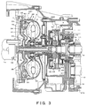
- the pump part 4 of the fluid coupling 2 is integrally disposed in the casing 18 that is connected to the output shaft (crankshaft) 1a of the engine.
- the pump part 4 is installed by means of bearings 29 so that the pump part 4 is free to rotate relative to the input shaft 3a of the clutch 3.
- the turbine part 5 is connected to the input shaft 3a of the clutch 3 so as to face the pump part 4.
- the stator part 6 has been omitted from the figures.
- a clutch disk 31 is connected to the turbine part 5 via a damper spring 30.
- the clutch disk 31 is installed facing the casing 18 so that this clutch disk 31 can slide in the axial direction relative to the turbine hub 32 of the turbine part 5, and a clutch facing 33 is mounted on the outside part of the clutch disk 31 that faces the abovementioned casing 18.
- An inside passage 36 is formed in the input shaft 3a, and an outside passage 37 is formed around the outer circumference of this input shaft 3a.
- the clutch facing 33 of the clutch disk 31 makes frictional contact with the casing 18, so that the rotation of the casing 18 is transmitted to the turbine part 5 from the clutch disk 31 via the damper spring 30, and the pump part 4 and turbine part 5 are mechanically coupled.
- respective pluralities of clutch plates 41 are differently spline-engaged with the input side and output side inside a clutch casing 40 filled with oil, and engagement and disengagement of the clutch are accomplished by pressing these clutch plates 41 against each other, or releasing the clutch plates 41, by means of a clutch piston 42.
- the clutch piston 42 is constantly driven in the direction of disengagement by a clutch spring 43, and the clutch 3 is engaged when a hydraulic pressure that exceeds this driving force is applied to the clutch piston 42.
- the rotation matching braking device 70 consists of a friction plate 94 which rotates together with the drum 91 side (input side) between a drum 91 installed on the input shaft 8 of the transmission T/M and the housing 92 (fixed side) of the transmission T/M, a pressing plate 93 which is installed on the side of the housing 92 so that this pressing plate 93 can move toward or away from the friction plate 94, and a pushing piston 74 which is disposed on the side of the housing 92 of the transmission T/M so that this pushing piston 74 presses the friction plate 94 and pressing plate 93 together.
- the friction plate 94 and pressing plate 93 are joined together as a result of the pushing piston 74 being pushed by a spring 73, whereby the braking performed by the gear-in parking brake is driven into a constant operating state. Furthermore, the braking is released (disengaged) by supplying hydraulic fluid to the cylinder chamber 98 of the pushing piston 94 from a fluid pipe channel 97 used for hydraulic fluid supply.
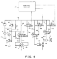
- Fig. 4 shows details of the hydraulic circuit 19 that operates the fluid coupling 2, lock-up device 20, wet type multi-plate clutch 3 and rotation matching mechanism (braking device) 70.
- oil from an oil tank 45 is sucked in and discharged by a hydraulic pump OP via a filter F.
- the discharge pressure is regulated by a relief valve 47 so that the hydraulic fluid that is supplied to the hydraulic fluid supply line 46 is maintained at a constant pressure.
- a lock-up five-way valve 49 which switches the hydraulic fluid to the fluid coupling 2 is connected to the hydraulic fluid supply line 46 via a line 48.
- a hydraulic fluid return line 50 which returns the hydraulic fluid to the oil tank 45 is connected to this lock-up five-way valve 49, and a throttle valve 51, cooler 52 and opening-and-closing valve 53 are connected to the hydraulic fluid return line 50.
- the opening-and-closing valve 53 is ordinarily closed, and is opened by hydraulic fluid from a pilot line 54 that is connected to the hydraulic fluid supply line 46.
- the switching of the lock-up five-way valve 49 is controlled by a lock-up clutch solenoid 56 that is connected to the pilot line 55 of the hydraulic fluid supply line 46.
- hydraulic fluid from the line 48 flows from the line 57 into the outside passage 37 explained in Fig. 2, and flows into the turbine part 5 and pump part 4; this hydraulic fluid passes through the line 58 from the inside passage 36, and is returned to the hydraulic fluid return line 50 via the lock-up five-way valve 49.
- the lock-up five-way valve 49 is switched by hydraulic fluid from the pilot line 55, so that the hydraulic fluid from the line 48 flows into the inside passage 36 from the line 58, and flows into the pump part 4 and turbine part 5.
- This hydraulic fluid is supplied to the line 57, and the side of the line 57 is closed. In this case, a portion of the oil that is supplied to the line 58 is returned to the hydraulic fluid return line 50 via the throttle valve 59.
- the wet type multi-plate clutch 3 is connected to the hydraulic fluid supply line 46 via a line 60, and a clutch switching three-way valve 61 is connected to this line 60.
- the actuation of this clutch switching three-way valve 61 is controlled by a variable-speed clutch control solenoid 63 which is connected to the pilot line 62 of the hydraulic fluid supply line 46.
- the clutch switching three-way valve 61 is in a closed position under ordinary conditions. In this state, the clutch is driven in the direction of disengagement by the spring 42.
- a pilot control three-way electromagnetic valve 63 is actuated in the opening direction, the clutch switching three-way valve 61 is opened by hydraulic fluid from the pilot line 62 so that hydraulic fluid is supplied to the wet type three-way clutch 3, and the clutch is actuated in the direction of engagement.
- a braking force is applied by the spring 73 under ordinary conditions.
- the gear parking brake force is released so that the device can be disengaged.
- the braking force can be regulated by regulating the degree of advance and retraction of the pushing piston 74.
- the pushing piston 74 is connected to the hydraulic fluid supply line 46 via a line 75.
- a braking three-way valve 76 is connected to this line 75, and the actuation of this braking three-way valve 76 is controlled by a brake control solenoid 78 that is connected to the pilot line 77 of the hydraulic fluid supply line 46.
- the control device 22 places the brake control solenoid 78 in a state in which the port shown in Fig. 4 is connected. Accordingly, the pushing piston 74 is not actuated but maintained in an extended state by the spring 76, so that the braking force of the rotation matching braking device 70 is maintained.
- the control device 22 can regulate the amount of hydraulic fluid that is sent to the pushing piston 74 from the braking three-way valve 76 by outputting a duty pulse signal, whose duty ratio is appropriately varied between 0 and 100%, to the brake control solenoid 78; in this way, the control device 22 can regulate the braking force.
- lock-up clutch solenoid 56 and the variable-speed clutch control solenoid 63 are also actuated by electrical signals from the control device 22.
- the driving force of the engine E is transmitted via the fluid coupling 2, wet type multi-plate clutch 3 and transmission T/M, in that order.
- the lock-up clutch 7 and the wet type multi-plate clutch 3 are disengaged.
- the wet type multi-plate clutch 3 is engaged.
- the turbine part 5 of the fluid coupling 2 is stopped from the side of the driven wheels; accordingly, only the pump part 4 rotates, so that a creeping force is generated.
- the brake pedal 25 is released or the accelerator pedal 23 is depressed, the turbine part 5 rotates so that the driving force is transmitted to the side of the transmission T/M.
- Fig. 1 shows a flow chart of the rotation matching mechanism of the automatic clutch type transmission when up-shifting is performed by the control device 22 shown in Fig. 2.
- control device 22 detects the engine rotation by means of the rotation sensor 28T, and detects the vehicle speed by means of the rotation sensor 27B. Furthermore, in regard to the operating state of the shift lever 21, the control device 22 detects the gear and neutral position from the shift sensor and stroke sensor.
- step 1 the actual engine rpm and the envisioned rpm A are compared, and if the envisioned rpm A is higher than the engine rpm (YES), a command is sent (84) indicating that the duty ratio of the duty pulse that is outputted to the brake control solenoid 78 is to be B%.
- the pushing piston 74 shown in Fig. 4 returns an amount of the oil accumulated inside the cylinder chamber corresponding to a duty ratio of B% to the tank 45 by way of the braking three-way valve 76, so that the spring 73 is extended by the pushing piston 74, thus causing a braking force that corresponds to a duty ratio of B% to be applied.
- step 2 the processing returns to the judgement of step 1, and the engine rpm and envisioned rpm A are compared; here, if the envisioned rpm A is higher (YES), a command is sent (84) indicating that the duty ratio of the duty pulse successively output to the brake control solenoid 78 is to be B%, so that the braking force of the rotation matching braking device 70 is regulated.
- step 1 When the engine rpm drops below the envisioned rpm A in the judgement made in step 1, that is, when synchronization is achieved (NO), the duty ratio of the brake control solenoid 78 is returned to 0% (85), so that the braking force of the rotation matching braking device 70 is released; accordingly, a shift is made (86) to the next shift stage, and control is ended (87).
- the rotation of the input shaft 8 is braked using the braking force of the rotation matching braking device 70, so that the rotation of the dog D of the gear stage to which a shift is being made and the rotation of the hub H of the sleeve S that is being shifted can by synchronized.
- this rotation matching braking device 70 is located on the side of the fluid coupling 2 and wet type multi-plate clutch 3, so that ATF can be used for brake lubrication. Accordingly, superior frictional characteristics are obtained, and a gear-in parking function in cold areas can also be used.
- rotation matching when up-shifting was described in the abovementioned embodiment.
- rotation matching is also performed when down-shifting; in this case, the control device 22 controls the rotation of the engine so that synchronization is obtained.
Landscapes
- Engineering & Computer Science (AREA)
- General Engineering & Computer Science (AREA)
- Mechanical Engineering (AREA)
- Hydraulic Clutches, Magnetic Clutches, Fluid Clutches, And Fluid Joints (AREA)
- Control Of Transmission Device (AREA)
- Control Of Driving Devices And Active Controlling Of Vehicle (AREA)
- Mechanical Operated Clutches (AREA)
- Braking Arrangements (AREA)
- Structure Of Transmissions (AREA)
- Gear-Shifting Mechanisms (AREA)
Applications Claiming Priority (2)
| Application Number | Priority Date | Filing Date | Title |
|---|---|---|---|
| JP2001206658 | 2001-07-06 | ||
| JP2001206658A JP2003021199A (ja) | 2001-07-06 | 2001-07-06 | 自動クラッチ式変速機の回転合わせ機構 |
Publications (2)
| Publication Number | Publication Date |
|---|---|
| EP1273831A2 true EP1273831A2 (de) | 2003-01-08 |
| EP1273831A3 EP1273831A3 (de) | 2003-10-08 |
Family
ID=19042756
Family Applications (1)
| Application Number | Title | Priority Date | Filing Date |
|---|---|---|---|
| EP02015085A Withdrawn EP1273831A3 (de) | 2001-07-06 | 2002-07-05 | Eingangswellenbremssteuerung zum Synchronisieren eines Getriebehalbautomaten |
Country Status (3)
| Country | Link |
|---|---|
| US (1) | US20030022754A1 (de) |
| EP (1) | EP1273831A3 (de) |
| JP (1) | JP2003021199A (de) |
Cited By (2)
| Publication number | Priority date | Publication date | Assignee | Title |
|---|---|---|---|---|
| WO2006032317A1 (de) * | 2004-09-22 | 2006-03-30 | Zf Friedrichshafen Ag | Verfahren zur erweiterung der funktion einer getriebebremse |
| WO2009135725A2 (de) * | 2008-05-09 | 2009-11-12 | Zf Friedrichshafen Ag | Verfahren zur schaltsteuerung eines automatisierten schaltgetriebes |
Families Citing this family (5)
| Publication number | Priority date | Publication date | Assignee | Title |
|---|---|---|---|---|
| JP4867104B2 (ja) * | 2001-08-10 | 2012-02-01 | いすゞ自動車株式会社 | 変速機のシフトアシスト装置 |
| JP2011094760A (ja) * | 2009-11-02 | 2011-05-12 | Inasaka Gear Mfg Co Ltd | 単車用変速機のシフト補助装置 |
| DE102011100857A1 (de) * | 2011-05-06 | 2012-11-08 | Audi Ag | Doppelkupplungsgetriebe |
| DE102016225401A1 (de) * | 2016-12-19 | 2018-06-21 | Zf Friedrichshafen Ag | Verfahren zum Betätigen einer Parksperre eines Kraftfahrzeugs |
| CN115013520B (zh) * | 2022-06-17 | 2024-05-17 | 潍柴动力股份有限公司 | Amt变速箱中间轴制动控制方法、装置及控制器 |
Citations (6)
| Publication number | Priority date | Publication date | Assignee | Title |
|---|---|---|---|---|
| US3667309A (en) * | 1970-10-14 | 1972-06-06 | Caterpillar Tractor Co | Multi speed drive transmission |
| US3834499A (en) * | 1971-09-25 | 1974-09-10 | Fiat Spa | Clutch, brake and motor controls for synchronized gear shifting |
| GB2012892A (en) * | 1978-01-24 | 1979-08-01 | Dana Corp | Mechanical Automatic Transmission |
| DE19826068A1 (de) * | 1998-06-12 | 1999-12-16 | Zahnradfabrik Friedrichshafen | Gemeinsame Betätigung von Kupplung und Getriebebremse |
| EP1013973A2 (de) * | 1998-11-13 | 2000-06-28 | Eaton Corporation | Unabhängige Steuerung von Dauerbremsen auf Getriebeseite und Motorseite während des gangschaltens |
| EP1065407A1 (de) * | 1999-07-02 | 2001-01-03 | MAGNETI MARELLI S.p.A. | Getriebeeinheit für Kraftfahrzeuge |
Family Cites Families (10)
| Publication number | Priority date | Publication date | Assignee | Title |
|---|---|---|---|---|
| US1880066A (en) * | 1930-11-06 | 1932-09-27 | Universal Gear Shift Corp | Gear shifting mechanism |
| US3572479A (en) * | 1969-07-24 | 1971-03-30 | Gen Motors Corp | Step-ratio transmissions with fluid operated synchronizing brake |
| US3709068A (en) * | 1969-12-29 | 1973-01-09 | Y Mohri | Power transmission |
| US3645367A (en) * | 1970-05-25 | 1972-02-29 | White Farm Equip | Operator for clutch and synchronizer brake |
| EP0088486A3 (de) * | 1982-02-05 | 1985-05-22 | Automotive Products Public Limited Company | Übertragung einer Drehbewegung |
| US4531430A (en) * | 1982-12-27 | 1985-07-30 | Eaton Corporation | Throttle modulator |
| US4581949A (en) * | 1983-09-15 | 1986-04-15 | Zahnradfabrik Friedrichshafen Ag | Hydrostatic/mechanical transmission system |
| DE4124384C1 (de) * | 1991-07-23 | 1993-01-28 | Mercedes-Benz Aktiengesellschaft, 7000 Stuttgart, De | |
| SE502150C2 (sv) * | 1993-12-30 | 1995-09-04 | Saab Scania Ab | Förfarande och anordning för adaptivt frånslag av avgasbroms i samband med uppväxling |
| US5901606A (en) * | 1996-06-18 | 1999-05-11 | Kubota Corporation | Transmission for a tractor |
-
2001
- 2001-07-06 JP JP2001206658A patent/JP2003021199A/ja active Pending
-
2002
- 2002-07-02 US US10/187,822 patent/US20030022754A1/en not_active Abandoned
- 2002-07-05 EP EP02015085A patent/EP1273831A3/de not_active Withdrawn
Patent Citations (6)
| Publication number | Priority date | Publication date | Assignee | Title |
|---|---|---|---|---|
| US3667309A (en) * | 1970-10-14 | 1972-06-06 | Caterpillar Tractor Co | Multi speed drive transmission |
| US3834499A (en) * | 1971-09-25 | 1974-09-10 | Fiat Spa | Clutch, brake and motor controls for synchronized gear shifting |
| GB2012892A (en) * | 1978-01-24 | 1979-08-01 | Dana Corp | Mechanical Automatic Transmission |
| DE19826068A1 (de) * | 1998-06-12 | 1999-12-16 | Zahnradfabrik Friedrichshafen | Gemeinsame Betätigung von Kupplung und Getriebebremse |
| EP1013973A2 (de) * | 1998-11-13 | 2000-06-28 | Eaton Corporation | Unabhängige Steuerung von Dauerbremsen auf Getriebeseite und Motorseite während des gangschaltens |
| EP1065407A1 (de) * | 1999-07-02 | 2001-01-03 | MAGNETI MARELLI S.p.A. | Getriebeeinheit für Kraftfahrzeuge |
Cited By (8)
| Publication number | Priority date | Publication date | Assignee | Title |
|---|---|---|---|---|
| WO2006032317A1 (de) * | 2004-09-22 | 2006-03-30 | Zf Friedrichshafen Ag | Verfahren zur erweiterung der funktion einer getriebebremse |
| EP1895200A3 (de) * | 2004-09-22 | 2008-10-01 | Zf Friedrichshafen Ag | Verfahren zur Erweiterung der Funktion einer Getriebebremse |
| EP1895201A3 (de) * | 2004-09-22 | 2008-10-01 | Zf Friedrichshafen Ag | Verfahren zur Erweiterung der Funktion einer Getriebebremse |
| CN101027509B (zh) * | 2004-09-22 | 2012-08-29 | Zf腓德烈斯哈芬股份公司 | 用于扩展传动系制动器的功能的方法 |
| US9387848B2 (en) | 2004-09-22 | 2016-07-12 | Zf Friedrichshafen Ag | Method for broadening the function of a transmission brake |
| WO2009135725A2 (de) * | 2008-05-09 | 2009-11-12 | Zf Friedrichshafen Ag | Verfahren zur schaltsteuerung eines automatisierten schaltgetriebes |
| WO2009135725A3 (de) * | 2008-05-09 | 2010-03-18 | Zf Friedrichshafen Ag | Verfahren zur schaltsteuerung eines automatisierten schaltgetriebes |
| US8668622B2 (en) | 2008-05-09 | 2014-03-11 | Zf Friedrichshafen Ag | Shift control method in an automated manual transmission |
Also Published As
| Publication number | Publication date |
|---|---|
| JP2003021199A (ja) | 2003-01-24 |
| US20030022754A1 (en) | 2003-01-30 |
| EP1273831A3 (de) | 2003-10-08 |
Similar Documents
| Publication | Publication Date | Title |
|---|---|---|
| EP0308072B1 (de) | Überbrückungs- und Schaltkupplungsanordnung für einen Drehmomentwandler | |
| US6460425B1 (en) | Twin clutch automated transmission | |
| EP2918870B1 (de) | Mehrkupplungsgetriebe für ein kraftfahrzeug | |
| EP1413804B1 (de) | Fahrzeuggetriebe | |
| US4784019A (en) | Torque converter disconnect and bypass clutch structure for automatic mechanical transmission | |
| EP0316869B1 (de) | Automatisiertes, mechanische Getriebe zum Einsatz in Nutzfahrzeugen | |
| US4517859A (en) | Shift up clutch control in a multiple clutch type gear transmission for automobile | |
| US8528433B2 (en) | Drive assembly comprising two clutches at the input end, and method for the operation thereof | |
| US6648795B2 (en) | Transmission system for vehicle | |
| US6397994B1 (en) | Powershift transmission with engine clutch assembly | |
| EP0200335A2 (de) | Strömungswandler mit Kupplungsanordnung zum Überbrücken und Unterbrechen für automatische mechanische Getriebe | |
| JP2003039960A (ja) | 手動変速機及びその変速制御装置 | |
| US6544142B2 (en) | Transmission system for vehicle | |
| EP1273831A2 (de) | Eingangswellenbremssteuerung zum Synchronisieren eines Getriebehalbautomaten | |
| KR20110084101A (ko) | 트랜스미션용 클러치 제어 | |
| US4803901A (en) | Method and system for detecting the rotation rate of the output shaft of a torque converter | |
| JP5145759B2 (ja) | 油圧制御装置 | |
| JP2922084B2 (ja) | 変速ギヤの同期装置 | |
| JP2844152B2 (ja) | 自動変速装置の給油装置 | |
| US5207123A (en) | Electrohydraulic control for an automatic transmission | |
| JP2922082B2 (ja) | 変速ギヤの同期装置 | |
| JP4110744B2 (ja) | 自動クラッチ式変速機のロックアップクラッチ制御装置 | |
| JP2002166753A (ja) | 車両用動力伝達装置 | |
| JP2002307982A (ja) | 自動クラッチ式変速機の制御装置 | |
| JP2605084Y2 (ja) | 変速機の速度段切換え制御装置 |
Legal Events
| Date | Code | Title | Description |
|---|---|---|---|
| PUAI | Public reference made under article 153(3) epc to a published international application that has entered the european phase |
Free format text: ORIGINAL CODE: 0009012 |
|
| AK | Designated contracting states |
Kind code of ref document: A2 Designated state(s): AT BE BG CH CY CZ DE DK EE ES FI FR GB GR IE IT LI LU MC NL PT SE SK TR |
|
| AX | Request for extension of the european patent |
Free format text: AL;LT;LV;MK;RO;SI |
|
| PUAL | Search report despatched |
Free format text: ORIGINAL CODE: 0009013 |
|
| AK | Designated contracting states |
Kind code of ref document: A3 Designated state(s): AT BE BG CH CY CZ DE DK EE ES FI FR GB GR IE IT LI LU MC NL PT SE SK TR |
|
| AX | Request for extension of the european patent |
Extension state: AL LT LV MK RO SI |
|
| RIC1 | Information provided on ipc code assigned before grant |
Ipc: 7F 16H 103:02 Z Ipc: 7F 16H 63/48 B Ipc: 7F 16H 3/12 B Ipc: 7F 16H 61/04 A |
|
| STAA | Information on the status of an ep patent application or granted ep patent |
Free format text: STATUS: THE APPLICATION HAS BEEN WITHDRAWN |
|
| 18W | Application withdrawn |
Effective date: 20040226 |