EP0200335A2 - Strömungswandler mit Kupplungsanordnung zum Überbrücken und Unterbrechen für automatische mechanische Getriebe - Google Patents
Strömungswandler mit Kupplungsanordnung zum Überbrücken und Unterbrechen für automatische mechanische Getriebe Download PDFInfo
- Publication number
- EP0200335A2 EP0200335A2 EP86302068A EP86302068A EP0200335A2 EP 0200335 A2 EP0200335 A2 EP 0200335A2 EP 86302068 A EP86302068 A EP 86302068A EP 86302068 A EP86302068 A EP 86302068A EP 0200335 A2 EP0200335 A2 EP 0200335A2
- Authority
- EP
- European Patent Office
- Prior art keywords
- torque converter
- clutch
- friction
- transmission
- input shaft
- Prior art date
- Legal status (The legal status is an assumption and is not a legal conclusion. Google has not performed a legal analysis and makes no representation as to the accuracy of the status listed.)
- Granted
Links
Images


Classifications
-
- F—MECHANICAL ENGINEERING; LIGHTING; HEATING; WEAPONS; BLASTING
- F16—ENGINEERING ELEMENTS AND UNITS; GENERAL MEASURES FOR PRODUCING AND MAINTAINING EFFECTIVE FUNCTIONING OF MACHINES OR INSTALLATIONS; THERMAL INSULATION IN GENERAL
- F16H—GEARING
- F16H45/00—Combinations of fluid gearings for conveying rotary motion with couplings or clutches
- F16H45/02—Combinations of fluid gearings for conveying rotary motion with couplings or clutches with mechanical clutches for bridging a fluid gearing of the hydrokinetic type
-
- F—MECHANICAL ENGINEERING; LIGHTING; HEATING; WEAPONS; BLASTING
- F16—ENGINEERING ELEMENTS AND UNITS; GENERAL MEASURES FOR PRODUCING AND MAINTAINING EFFECTIVE FUNCTIONING OF MACHINES OR INSTALLATIONS; THERMAL INSULATION IN GENERAL
- F16H—GEARING
- F16H45/00—Combinations of fluid gearings for conveying rotary motion with couplings or clutches
- F16H2045/005—Combinations of fluid gearings for conveying rotary motion with couplings or clutches comprising a clutch between fluid gearing and the mechanical gearing unit
-
- F—MECHANICAL ENGINEERING; LIGHTING; HEATING; WEAPONS; BLASTING
- F16—ENGINEERING ELEMENTS AND UNITS; GENERAL MEASURES FOR PRODUCING AND MAINTAINING EFFECTIVE FUNCTIONING OF MACHINES OR INSTALLATIONS; THERMAL INSULATION IN GENERAL
- F16H—GEARING
- F16H45/00—Combinations of fluid gearings for conveying rotary motion with couplings or clutches
- F16H45/02—Combinations of fluid gearings for conveying rotary motion with couplings or clutches with mechanical clutches for bridging a fluid gearing of the hydrokinetic type
- F16H2045/021—Combinations of fluid gearings for conveying rotary motion with couplings or clutches with mechanical clutches for bridging a fluid gearing of the hydrokinetic type three chamber system, i.e. comprising a separated, closed chamber specially adapted for actuating a lock-up clutch
-
- F—MECHANICAL ENGINEERING; LIGHTING; HEATING; WEAPONS; BLASTING
- F16—ENGINEERING ELEMENTS AND UNITS; GENERAL MEASURES FOR PRODUCING AND MAINTAINING EFFECTIVE FUNCTIONING OF MACHINES OR INSTALLATIONS; THERMAL INSULATION IN GENERAL
- F16H—GEARING
- F16H45/00—Combinations of fluid gearings for conveying rotary motion with couplings or clutches
- F16H45/02—Combinations of fluid gearings for conveying rotary motion with couplings or clutches with mechanical clutches for bridging a fluid gearing of the hydrokinetic type
- F16H2045/0273—Combinations of fluid gearings for conveying rotary motion with couplings or clutches with mechanical clutches for bridging a fluid gearing of the hydrokinetic type characterised by the type of the friction surface of the lock-up clutch
- F16H2045/0284—Multiple disk type lock-up clutch
-
- F—MECHANICAL ENGINEERING; LIGHTING; HEATING; WEAPONS; BLASTING
- F16—ENGINEERING ELEMENTS AND UNITS; GENERAL MEASURES FOR PRODUCING AND MAINTAINING EFFECTIVE FUNCTIONING OF MACHINES OR INSTALLATIONS; THERMAL INSULATION IN GENERAL
- F16H—GEARING
- F16H45/00—Combinations of fluid gearings for conveying rotary motion with couplings or clutches
- F16H45/02—Combinations of fluid gearings for conveying rotary motion with couplings or clutches with mechanical clutches for bridging a fluid gearing of the hydrokinetic type
- F16H2045/0273—Combinations of fluid gearings for conveying rotary motion with couplings or clutches with mechanical clutches for bridging a fluid gearing of the hydrokinetic type characterised by the type of the friction surface of the lock-up clutch
- F16H2045/0294—Single disk type lock-up clutch, i.e. using a single disc engaged between friction members
Definitions
- the present invention relates to automatic mechanical transmission systems including a throttle controlled engine, a mechanical change gear transmission and a fluid coupling, such as torque converter, interposed the engine and transmission.
- the present invention relates to a torque converter disconnect and by-pass clutch structure for such system.
- the present invention relates to a torque converter disconnect and by-pass clutch structure for an automatic mechanical transmission system utilizing a mechanical change gear transmission and a power synchronizer mechanism.
- the drawbacks of the prior art are minimized or overcome by the provision of an automatic mechanical transmission system utilizing a mechanical change gear transmission of a structure identical or substantially identical to the structure of transmissions intended for manual usage, providing the advantages of a torque converter for vehicle start-ups and the advantages of non-slipping connection between the engine and transmission at higher ve- hide speeds/gear ratios and providing relatively rapid synchronization of the transmission positive jaw clutches.
- 3,478,851 or 4,023,443 is also added for synchronizing the transmission positive jaw clutches. It has been found, by way of example, that in one typical compound, nine-speed mechanical change gear transmission equipped with a power synchronizer mechanism, the input shaft may be accelerated and decelerated, for downshifts and upshifts, respectively, at about 2000 RPM/second. This compares very favorably with the expected rates of about 1500 RPM/second and 700 RPM/second, for acceleration and deceleration, respectively, of a transmission input shaft by utilizing only engine speed manipulation. Additionally, when utilizing a power synchronizer mechanism, the input shaft speed is not limited to the maximum governed engine speed as is the case when synchronizing with engine speed manipulation.
- a torque converter is drivingly interposed the drive engine and transmission.
- a torque converter disconnect and by-pass clutch structure is provided comprising a first and a second separate, independently operable, clutches, preferably friction clutches, for coupling the torque converter driven member or turbine to the transmission input shaft and for coupling the torque converter input or impeller (i.e. the engine output) to the transmission input shaft, respectively.
- the torque converter is drivingly interconnected between the engine and transmission only when the first coupling is engaged and the second disengaged.
- the torque converter is by-passed, i.e. the transmission driven directly from the engine, whenever the second clutch is engaged, regardless of the condition of the first clutch.
- the transmission input shaft is disconnected from the engine torque and also from the inertia of the torque converter allowing the jaw clutches to be easily disengaged, the power synchronizer mechanism to act quickly due to relatively low inertia on the input shaft and also allowing a selected gear to be pre-engaged with the vehicle at rest and in the drive condition.
- Another object of the present invention is to provide a new and improved automatic mechanical transmission system utilizing a torque converter drivingly interposed the engine and mechanical transmission and further utilizing a torque converter disconnect and by-pass clutch structure.
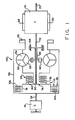
- the torque converter disconnect and by-pass clutch assembly 10 of the present invention, and an automatic mechanical transmission system 12 utilizing same, are schematically illustrated in Figures 1 and 2.
- the term "automatic mechanical transmission system” as used herein, shall mean a system comprising at least a throttle device controlled heat engine, a multi-speed jaw. clutch type change gear transmission, a non-positive coupling device such as a master friction clutch and/or a fluid coupling interposed the engine and the transmission and a control unit for automatically controlling same.
- Such systems will, of course, also include sensors and/or actuators for sending input signals to and/or receiving command output signals from the control unit.
- the automatic mechanical transmission system 12 of the present invention is intended for use on a land vehicle, such as a heavy duty truck, but is not limited to such use.
- the automatic mechanical transmission system 12 illustrated includes an automatic multi-speed mechanical change gear transmission 14 driven by a prime mover throttle device controlled engine 16 (such as a diesel engine) through a fluid coupling or torque converter assembly 20.
- the output of the automatic transmission 14 is an output shaft 22 which is adapted for driving connection to an appropriate vehicle component such as the differential of a drive axle, a transfer case, or the like as is well known in the prior art.
- the torque converter disconnect and by-pass clutch assembly 10 includes two separate, independently engageable clutches, preferably friction clutches, a torque converter disconnect clutch 24 and a torque converter by-pass clutch 26.
- the transmission 14 includes a transmission operating mechanism 28 which is preferably in the format of a pressurized fluid actuated shifting assembly of the type disclosed in above-mentioned United States Patent No. 4,445,393.
- the transmission also preferably includes a power synchronizer assembly 30 which may be of the type illustrated and disclosed in above-mentioned United States Patent Nos. 3,478,851 or 4,023,443.
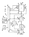
- the above-mentioned power train components are acted upon and monitored by several devices, each of which are known in the prior art and will be discussed in greater detail below.
- These devices may include a throttle position monitor assembly 32, which senses the position of the operator controlled vehicle throttle pedal or other fuel throttling device, a throttle control 34 which controls the supply of fuel to the engine, an engine speed sensor assembly 36 which senses the rotational speed of the engine, a torque converter disconnect clutch operator 38 which operates the torque converter disconnect clutch 24, a torque converter by- pass clutch operator 40 which operates the torque converter by-pass clutch 26, a transmission input shaft speed sensor 42, a-transmission output shaft speed sensor 44, a transmission shifting mechanism operator 46 for controlling the operation of transmission shifting mechanism 28 and/or a power synchronizer mechanism actuator 48 for controlling the operation of power synchronizer mechanism 30.
- a throttle position monitor assembly 32 which senses the position of the operator controlled vehicle throttle pedal or other fuel throttling device
- a throttle control 34 which controls the supply of fuel to the engine
- an engine speed sensor assembly 36
- the above-mentioned devices supply information to and/or accept commands from an electronic central processing unit ("CPU") 50.
- the central processing unit or controller 50 is preferably based on a digital microprocessor, the specific configuration and structure of which form no part of the present invention.
- the central processing unit 50 also receives information from a shift control or mode selector assembly 52 by which the operator may select a reverse (R), a neutral (N) or several forward drive (D, D L ) modes of operation of the vehicle.
- R reverse
- N neutral
- D, D L forward drive
- the D mode of operation is for on-highway vehicle travel while the D L mode of operation is for off-road operation.
- a separate on-highway/off-highway selector switch may be provided.
- An electrical power source (nol shown) and/or source of pressurized fluid (nol shown) provides the electrical and/or pneumatic power the various sensing, operating and/or processing unit.
- Drive train components and controls therefor of the type described above are known in the prior art and may be appreciated in greater detail by reference to United States Patent Nos. 3,776,048; 3,038,889; 4,226,295 and 4,361,060, the disclosures of which are incorporated by reference.
- the central processing unit 50 receives inputs from the various sensors and/or operating devices.
- the central processing unit 50 may be provided with circuitry and/or logic for differentiating the input signals to provide calculated signals indicative of the rate of change of the various monitored devices, means to compare the input signals and/or memory means for storing certain input information, such as the direction of the last shift, and means for clearing the memory upon occurrence of predetermined events.
- Specific circuitry for providing the above-mentioned functions is known in the prior art and an example thereof may be seen by reference to above-mentioned United States Patent No.
- a purpose of the central processing unit 50 is to select, in accordance with predetermined logic rules such as a program (software and/or firmware) and current or stored parameters; the optimum gear ratio at which the transmission 14 should be operating and, if necessary, to command a gear change, or shift, into the selected optimum gear ratio.
- a program software and/or firmware
- current or stored parameters such as a program (software and/or firmware) and current or stored parameters; the optimum gear ratio at which the transmission 14 should be operating and, if necessary, to command a gear change, or shift, into the selected optimum gear ratio.
- an electronically controlled transmission can be programmed to enhance specific vehicle characteristics, such as fuel economy or performance. Selection of the D (on-highway drive) mode on the shift selector 52 by the driver indicates to the central processing unit 52 that peak performance is not required.
- the gear selection subsystem may select fourth or fifth gear as a starting gear and select subsequent shifts, both upshifts and downshifts, according to what are referred to as the on-highway shift profiles which are intended to enhance fuel economy.
- selection of the D, (off-highway drive) mode on the shift selector indicates to the central processing unit 50 a desire to operate at peak performance at the expense of fuel economy.
- the gear selection subsystem may select low gear or first gear as the starting gear in subsequent shifts, both upshifts and downshifts, at least in the lower gear ratios, will be according to what are referred to as the off-highway shift profiles which are intended to enhance vehicle performance at the expense of vehicle fuel economy.
- the torque converter assembly 20 is conventional in that it includes a fluid coupling of the torque converter type having an impeller 54 driven by the engine output or crank shaft 56 through a shroud 58, a turbine 60 hydraulically driven by the impeller and a stator or runner 62 which becomes grounded to a housing 64 via a one-way roller clutch 66 carried by a shaft 68 grounded to the housing 64.
- Shroud 58 also drives a pump 70 for pressurizing the torque converter, lubricating the transmission, selectively pressuring the transmission shifting mechanism 28 and/or power synchronizing mechanism 30 and/or operating the disconnect and by-pass clutches 24 and 26.
- Pump 70 may be of any known structure such as, for example, a well known crescent gear pump.
- the transmission 14 includes an input shaft 72 driven by the engine 16 via the torque converter assembly 20 and/or disconnect and by-pass clutch assembly 10.
- Transmission input shaft 72 carries a connecting member 74 fixed thereto for rotation therewith.
- Connecting member 74 includes a first portion 76 associated with the torque converter disconnect clutch 24 and a second portion 78 associated with the torque converter by-pass clutch 26.
- torque converter disconnect clutch 24 may be engaged or disengaged, independently of engagement or disengagement of by-pass clutch 26, to frictionally engage or disengage, respectively, the torque converter turbine 60 from the transmission input shaft 72 via portion 76 of connecting member 74.
- Torque converter by-pass clutch 26 may be frictionally engaged or disengaged, independent of the engagement or disengagement of disconnect clutch 24, to frictionally engage the engine crankshaft 56, and shroud 58 driven thereby, to the transmission input shaft 72 via member 78 of connecting member 74.
- torque converter by-pass clutch 26 Engagement of torque converter by-pass clutch 26 will engage the engine crankshaft 56, via shroud 58, directly with the transmission input shaft 72, regardless of the engaged or disengaged condition of torque converter disconnect clutch 24, and thus provides an effective by-pass for by-passing the torque converter 20 and driving transmission 14 directly from the engine 16. If the torque converter by-pass clutch 26 is disconnected, and the torque converter disconnect clutch 24 is engaged, the transmission 14 will be driven from engine 16 via the torque converter fluid coupling as is well known in the prior art. If the torque converter by-pass clutch 26 is disengaged and the torque converter disconnect clutch 24 is also disengaged, the transmission input shaft 72 is drivingly disengaged from any drive torque supplied by the engine or any inertial drag supplied by the torque converter.
- Disconnecting of the transmission input shaft 72 from the inertial affects of the engine and/or torque converter allows the rotational speed of the input shaft 72, and all transmission gearing drivingly connected thereto, to be accelerated or decelerated by the transmission power synchronizer mechanism 30 in a more rapid manner for purposes of more rapidly achieving synchronization during a downshift or upshift of the transmission and also allows the power synchronizer to cause the input shaft 72 to rotate at a rotational speed greater than any governed engine speed.
- transmission 14 is of the mechanical transmission type utilizing positive jaw type clutches.
- Positive clutches of this type are relatively compact and inexpensive as compared to frictional clutches and are very reliable if utilized in connection with some type of synchronizing means such as individual synchronizers and/or a power synchronizing mechanism.
- positive type clutches it is necessary and/or highly desireable that the driving torque and inertial forces on input shaft 72 be minimized when the jaw clutch members are to be disengaged from the previously engaged gear ratio and then re-engaged in the selected new gear ratio. Accordingly, when a fluid coupling such as a fluid torque converter is drivingly interposed between a drive engine and a positive mechanical transmission, it is important that a means to disconnect the transmission input shaft from the fluid coupling be provided.
- Change gear transmission 14 includes a transmission housing 80 having a bell housing portion 82 which encloses the torque converter 20 and disconnect and by-pass clutches, 24 and 26, and which is provided with a flange 84 for attachment to the drive engine.
- the housing 80 is provided with bearings 86 and 88 for rotatably supporting the input shaft 72 within the housing 80.
- Input shaft 72 carries transmission input gear 89 fixed for rotation therewith.
- torque converter 18 includes impeller 54, a turbine 60 and a stator 62 as is well known in the prior art.
- Stator 66 is supported in the housing by means of a one-way roller clutch 66 as is well known in the prior art.
- the impeller 54 is fixed for rotation to a shroud member 58 which is adapted to be driven by the engine 16 by means of engine drive splines 90, or the like, which are adapted for driving engagement with complimentary drive splines provided on the engine fly wheel.
- the gearing and positive clutch structure of transmission 14 is conventional and not illustrated nor described.
- the shroud 58 which surrounds assembly 10 and torque converter 20, is also adapted to drive pump 70 as by means of a spur gear 92 constantly engaged with pump drive gear 94.
- the pump 70 may also provide pressurized fluid for selective engagement and disengagement of the torque converter disconnect clutch 24 and/or torque converter by-pass clutch 26 as will be discussed in greater detail below.
- housing 80, shaft 72 and/or shroud end cover 96 are provided with fluid passage ways and rotary fluid connections in a manner well known in the prior art.
- Torque converter disconnect and by-pass clutch structure 10 comprises a torque converter disconnect clutch 24 which is concentric with and generally surrounded by torque converter by-pass clutch 26 to provide a relatively axially compact structure.
- the torque converter disconnect and by- pass clutch structure 10 includes a connecting member 74 which is fixed for rotation with the input shaft 72 as at splined connection 98.
- Connecting member 74 includes a generally axially extending annular shaped wall member 100 having a plurality of inner diameter spline members 100a defining portion 76 and a plurality of outer diameter spline members 100b defining portion 78.
- a plurality oi friction members such as friction discs 102 are carried by splined member 76 for rotation therewith and extend radially inwardly therefrom.
- Friction discs 104 are carried by splined member 78 and extend radially outwardly therefrom.
- Friction discs 104 are interleaved with friction discs 106 carried by internal splines 108 on the shroud member 58 and extending radially inwardly thereform to define a friction disc pack for by-pass clutch 26 as is known in the prior art.
- Friction discs 102 are interleaved with friction discs 110 fixed for rotation on external splines 112 of a member 114 fixed for rotation with the turbine 60 and extend radially outwardly therefrom to define a clutch disc pack for torque converter disconnect clutch 24.
- Member 114 is fixed to turbine 60 by means of web member 116 and is rotatably supported on a hub portion 117 of connecting member 74.
- An annular axially inwardly extending cylinder 120 is defined in the forward end wall 96 of shroud 58 and receives an annular piston member 122 slideably and sealingly therein.
- Annular piston 122 and annular reaction member 124 receive the friction discs 104 and 106 axially therebetween for selective engagement and disengagement of by- pass clutch 26.
- Cylinder 120 may be selectively pressurized and depressurized, to engage and disengage, respectively, torque converter by-pass clutch 26 to connect the engine driven shroud 58 directly to the input shaft 72 via portion 78 of connecting member 74 by pressurized fluid from pump 70 supplied through passages in the cover 82, shaft 72 and/or end cover 96 and controlled by valve structure 40.
- Connecting member 74 defines an annular axially inwardly extending cylinder 128 in which an annular piston 130 is sealingly and slidably retained.
- Annular piston 130 and annular reaction member 132 receive the friction discs 102 and 110 axially therebetween for selective engagement and disengagement of the torque converter disconnect clutch 24.
- Pressurized fluid from pump 70 may be supplied to or vented from cylinder 128 by means of fluid passages defined in the hood 82, shaft 72 and/or end cover 96 and controlled by valve 38 controlling the flow of fluid to and from pump 70 to cylinder 128 or an hydraulic fluid reservoir (not shown).
- annular cylinders 120 and 128 may be individually and independently pressurized and/or vented for independent engagement or disengagement of the torque converter disconnect 24 and/or torque converter by-pass 26 clutches.
- a relatively axially compact structure is provided allowing a drive system comprising a torque converter fluid coupling to be drivingly interposed a drive engine and a mechanical change gear transmission wherein the transmission may be driven directly from the engine by means of a torque converter by-pass clutch, the transmission may be driven by the engine through the torque converter fluid coupling and/or the transmission may be disconnected from the engine and torque converter for purposes of providing a break in the torque and reduction in input shaft inertia for purposes of more rapidly synchronizing and shifting the transmission.
- the disconnect clutch 24 When the vehicle is at rest with the mode selector in the drive or off-highway drive mode, the disconnect clutch 24 will be engaged and the by- pass clutch 26 disengaged allowing for torque converter start-up with its well known advantages. At above a given vehicle speed and/or gear ratio, the advantages of torque converter operation are no longer required, and the increased efficiency of a direct drive between the drive engine and transmission is required. Under these conditions, the torque converter by-pass clutch 26 will be engaged allowing the transmission input shaft 72 to be driven directly from the engine via the torque converter shroud 58 and connecting member 74.
- both clutches 24 and 26 will be disengaged to shift from a previously engaged gear to neutral, to allow the power synchronizer 30 to synchronize the jaw clutch members of the gear to be engaged and to allow engagement of the synchronized jaw clutches of the gear to be engaged.
- the power synchronizing mechanism 30 may include a shaft 136 drivingly connected to a transmission countershaft 138 constantly in direct or indirect meshing engagement with the input gear 89 and input shaft 72.
- Shaft 136 may be selectively frictionally clutched to the housing 80 to decelerate the input shaft 72 and the gearing driven thereby and/or may be selectively frictionally clutched to a speed increasing drive train, such as a planetary speed increasing drive train, 140, driven off the output shaft 22, to accelerate the input shaft 72 and the gearing driven thereby.
- a speed increasing drive train such as a planetary speed increasing drive train, 140
- the clutching of the shaft 136 to the housing or to the gear train may be modulated as by pulse width modulation or the like.
Landscapes
- Engineering & Computer Science (AREA)
- General Engineering & Computer Science (AREA)
- Mechanical Engineering (AREA)
- Control Of Transmission Device (AREA)
- Structure Of Transmissions (AREA)
- Crushing And Pulverization Processes (AREA)
- Arrangement Of Transmissions (AREA)
Applications Claiming Priority (2)
| Application Number | Priority Date | Filing Date | Title |
|---|---|---|---|
| US71918085A | 1985-04-03 | 1985-04-03 | |
| US719180 | 1985-04-03 |
Publications (3)
| Publication Number | Publication Date |
|---|---|
| EP0200335A2 true EP0200335A2 (de) | 1986-11-05 |
| EP0200335A3 EP0200335A3 (en) | 1987-11-25 |
| EP0200335B1 EP0200335B1 (de) | 1989-11-15 |
Family
ID=24889069
Family Applications (1)
| Application Number | Title | Priority Date | Filing Date |
|---|---|---|---|
| EP86302068A Expired EP0200335B1 (de) | 1985-04-03 | 1986-03-20 | Strömungswandler mit Kupplungsanordnung zum Überbrücken und Unterbrechen für automatische mechanische Getriebe |
Country Status (6)
| Country | Link |
|---|---|
| EP (1) | EP0200335B1 (de) |
| JP (1) | JPS61233264A (de) |
| CN (1) | CN1014543B (de) |
| BR (1) | BR8601612A (de) |
| DE (1) | DE3666971D1 (de) |
| MX (2) | MX161836A (de) |
Cited By (12)
| Publication number | Priority date | Publication date | Assignee | Title |
|---|---|---|---|---|
| EP0308072A1 (de) * | 1987-09-17 | 1989-03-22 | Eaton Corporation | Überbrückungs- und Schaltkupplungsanordnung für einen Drehmomentwandler |
| GB2273534A (en) * | 1992-12-17 | 1994-06-22 | Daimler Benz Ag | Hydrodynamic torque converter with a lock-up clutch |
| BE1011015A3 (fr) * | 1995-12-06 | 1999-04-06 | Caterpillar Inc | Appareil de controle du couple d'une chaine cinematique et methode de fonctionnement de celui-ci. |
| FR2776355A1 (fr) * | 1998-03-23 | 1999-09-24 | Mannesmann Sachs Ag | Convertisseur de couple de torsion |
| KR101326819B1 (ko) * | 2011-07-29 | 2013-11-11 | 현대자동차주식회사 | 자동차의 토크 컨버터 |
| US10260613B2 (en) | 2017-06-08 | 2019-04-16 | GM Global Technology Operations LLC | Damper assemblies for engine disconnect clutches of motor vehicle powertrains |
| US10288159B2 (en) | 2016-05-13 | 2019-05-14 | GM Global Technology Operations LLC | Integrated clutch systems for torque converters of vehicle powertrains |
| US10323696B2 (en) | 2017-06-12 | 2019-06-18 | Gm Global Technology Operations Llc. | Dynamic latching mechanisms for selectable clutches of motor vehicle powertrains |
| US10337597B2 (en) | 2016-05-13 | 2019-07-02 | Gm Global Technology Operations Llc. | Engine disconnects with mechanical diodes for vehicle powertrains |
| US10358123B2 (en) | 2017-12-01 | 2019-07-23 | Gm Global Technology Operations Llc. | Multi-mode engine-disconnect clutch assemblies and control logic for hybrid electric vehicles |
| US10597022B2 (en) | 2018-02-01 | 2020-03-24 | GM Global Technology Operations LLC | Coordinated torque and speed control systems and logic for hybrid electric vehicles |
| US10809733B2 (en) | 2018-10-16 | 2020-10-20 | GM Global Technology Operations LLC | Intelligent motor vehicles, systems, and control logic for driver behavior coaching and on-demand mobile charging |
Families Citing this family (10)
| Publication number | Priority date | Publication date | Assignee | Title |
|---|---|---|---|---|
| JPH0729337Y2 (ja) * | 1987-10-27 | 1995-07-05 | 日産ディーゼル工業株式会社 | 車両用動力伝達装置 |
| CN1327148C (zh) * | 2004-02-20 | 2007-07-18 | 吉林大学 | 具有双离合器的液力变矩器 |
| JP4606224B2 (ja) * | 2005-03-31 | 2011-01-05 | 本田技研工業株式会社 | 車両用動力伝達装置 |
| CN101408244B (zh) * | 2007-10-08 | 2010-12-01 | 刘海平 | 机械液力无级变速器和方法、及车辆机械液力无级变速器 |
| CN101856970B (zh) * | 2010-06-13 | 2013-05-08 | 程秀生 | 重型及商用汽车液力辅助起步与液压辅助制动装置 |
| US9695773B2 (en) * | 2013-03-14 | 2017-07-04 | Ford Global Technologies, Llc | Method and system for improving engine starting |
| CN104141764A (zh) * | 2013-11-18 | 2014-11-12 | 成都科创佳思科技有限公司 | 液力变矩器 |
| EP3236101B1 (de) * | 2016-04-20 | 2021-03-17 | Ortlinghaus-Werke GmbH | Kupplungsbaugruppe |
| CN108644341A (zh) * | 2018-06-29 | 2018-10-12 | 吉林大学 | 一种基于速度识别轨道工程车多液力传动箱及其控制方法 |
| US11040611B2 (en) * | 2019-08-27 | 2021-06-22 | GM Global Technology Operations LLC | Turbine mounted P2 front wheel drive transmission arrangement |
Family Cites Families (12)
| Publication number | Priority date | Publication date | Assignee | Title |
|---|---|---|---|---|
| US4023443A (en) * | 1972-12-15 | 1977-05-17 | Nissan Motor Co., Ltd. | Transmission synchronizing mechanism |
| FR2266061B1 (de) * | 1974-03-29 | 1979-02-16 | Berliet Automobiles | |
| JPS613984B2 (de) * | 1974-08-19 | 1986-02-06 | Toyota Motor Co Ltd | |
| US4066157A (en) * | 1976-08-06 | 1978-01-03 | Borg-Warner Corporation | Impeller disconnect and brake mechanism |
| DE2714559C3 (de) * | 1977-04-01 | 1979-09-13 | Robert Bosch Gmbh, 7000 Stuttgart | Vorrichtung zur Steuerung von Stufengetrieben in Kraftfahrzeugen |
| US4375171A (en) * | 1978-03-06 | 1983-03-01 | Eaton Corporation | Automatic transmission |
| US4261216A (en) * | 1978-12-26 | 1981-04-14 | Eaton Corporation | Synchronized transmission |
| JPS56167950A (en) * | 1980-05-26 | 1981-12-23 | Nissan Motor Co Ltd | Lockup-type automatic transmission |
| JPS5749010U (de) * | 1980-09-04 | 1982-03-19 | ||
| FR2525312B1 (fr) * | 1982-04-20 | 1987-07-03 | Valeo | Transmission a organe d'accouplement hydraulique et embrayage de verrouillage, notamment pour vehicule automobile |
| FR2535002B1 (fr) * | 1982-10-26 | 1988-03-25 | Valeo | Transmission a organe d'accouplement hydraulique et embrayage de verrouillage, notamment pour vehicule automobile |
| DE3306000C2 (de) * | 1983-02-22 | 1987-02-05 | Zahnradfabrik Friedrichshafen Ag, 7990 Friedrichshafen | Steuereinrichtung für eine Wandlerschaltkupplung |
-
1986
- 1986-03-20 EP EP86302068A patent/EP0200335B1/de not_active Expired
- 1986-03-20 DE DE8686302068T patent/DE3666971D1/de not_active Expired
- 1986-04-02 CN CN 86102120 patent/CN1014543B/zh not_active Expired
- 1986-04-02 BR BR8601612A patent/BR8601612A/pt not_active IP Right Cessation
- 1986-04-02 MX MX206186A patent/MX161836A/es unknown
- 1986-04-02 MX MX2395586A patent/MX171752B/es unknown
- 1986-04-03 JP JP7752586A patent/JPS61233264A/ja active Pending
Cited By (15)
| Publication number | Priority date | Publication date | Assignee | Title |
|---|---|---|---|---|
| EP0308072A1 (de) * | 1987-09-17 | 1989-03-22 | Eaton Corporation | Überbrückungs- und Schaltkupplungsanordnung für einen Drehmomentwandler |
| GB2273534A (en) * | 1992-12-17 | 1994-06-22 | Daimler Benz Ag | Hydrodynamic torque converter with a lock-up clutch |
| US5441135A (en) * | 1992-12-17 | 1995-08-15 | Mercedes-Benz Ag | Hydrodynamic torque converter with lock-up clutch |
| GB2273534B (en) * | 1992-12-17 | 1996-02-07 | Daimler Benz Ag | Hydrodynamic torque converter with a lock-up clutch |
| BE1011015A3 (fr) * | 1995-12-06 | 1999-04-06 | Caterpillar Inc | Appareil de controle du couple d'une chaine cinematique et methode de fonctionnement de celui-ci. |
| US6079529A (en) * | 1998-03-23 | 2000-06-27 | Mannesmann Sachs Ag | Torque converter |
| FR2776355A1 (fr) * | 1998-03-23 | 1999-09-24 | Mannesmann Sachs Ag | Convertisseur de couple de torsion |
| KR101326819B1 (ko) * | 2011-07-29 | 2013-11-11 | 현대자동차주식회사 | 자동차의 토크 컨버터 |
| US10288159B2 (en) | 2016-05-13 | 2019-05-14 | GM Global Technology Operations LLC | Integrated clutch systems for torque converters of vehicle powertrains |
| US10337597B2 (en) | 2016-05-13 | 2019-07-02 | Gm Global Technology Operations Llc. | Engine disconnects with mechanical diodes for vehicle powertrains |
| US10260613B2 (en) | 2017-06-08 | 2019-04-16 | GM Global Technology Operations LLC | Damper assemblies for engine disconnect clutches of motor vehicle powertrains |
| US10323696B2 (en) | 2017-06-12 | 2019-06-18 | Gm Global Technology Operations Llc. | Dynamic latching mechanisms for selectable clutches of motor vehicle powertrains |
| US10358123B2 (en) | 2017-12-01 | 2019-07-23 | Gm Global Technology Operations Llc. | Multi-mode engine-disconnect clutch assemblies and control logic for hybrid electric vehicles |
| US10597022B2 (en) | 2018-02-01 | 2020-03-24 | GM Global Technology Operations LLC | Coordinated torque and speed control systems and logic for hybrid electric vehicles |
| US10809733B2 (en) | 2018-10-16 | 2020-10-20 | GM Global Technology Operations LLC | Intelligent motor vehicles, systems, and control logic for driver behavior coaching and on-demand mobile charging |
Also Published As
| Publication number | Publication date |
|---|---|
| JPS61233264A (ja) | 1986-10-17 |
| EP0200335A3 (en) | 1987-11-25 |
| CN1014543B (zh) | 1991-10-30 |
| CN86102120A (zh) | 1987-01-28 |
| MX161836A (es) | 1990-12-28 |
| DE3666971D1 (en) | 1989-12-21 |
| BR8601612A (pt) | 1986-12-09 |
| MX171752B (es) | 1993-11-11 |
| EP0200335B1 (de) | 1989-11-15 |
Similar Documents
| Publication | Publication Date | Title |
|---|---|---|
| US4784019A (en) | Torque converter disconnect and bypass clutch structure for automatic mechanical transmission | |
| EP0308072B1 (de) | Überbrückungs- und Schaltkupplungsanordnung für einen Drehmomentwandler | |
| EP0200335B1 (de) | Strömungswandler mit Kupplungsanordnung zum Überbrücken und Unterbrechen für automatische mechanische Getriebe | |
| EP0512726B1 (de) | Strategie zur Steuerung der Antriebstrang-Drehmomentbegrenzung unter Verwendung einer Motorsteuerung | |
| CA2148401C (en) | Power synchronizer for a compound transmission | |
| US7318788B2 (en) | Gearshift procedure for vehicles with engaged clutch-dependent power take-off | |
| US4614126A (en) | Power synchronizer | |
| EP0641958B1 (de) | Getriebeschaltung mit veränderlichem Gleichlaufgeschwindigkeitsbereich | |
| US5274553A (en) | Torque converter slip rate based skip power downshift control strategy | |
| EP0512708B1 (de) | Verbund-Herunterschaltverfahren und -System mit kickdown | |
| US5186291A (en) | Transmission for a vehicle | |
| US4296645A (en) | Powershift transmission with direct drive and modulated torque converter drive in forward and reverse | |
| JP2004522910A (ja) | 自動車駆動ユニット | |
| WO2003078197A1 (en) | Motor vehicle drive unit | |
| SE521517C2 (sv) | Växellåda för motorfordon med en automatisk koppling | |
| SE525632C2 (sv) | Flerväxlad transmission för motorfordon jämte växlingsförfarande | |
| JPH0545832B2 (de) | ||
| SE467168B (sv) | Transmission foer ett fordon samt foerfarande foer reglering av densamma |
Legal Events
| Date | Code | Title | Description |
|---|---|---|---|
| PUAI | Public reference made under article 153(3) epc to a published international application that has entered the european phase |
Free format text: ORIGINAL CODE: 0009012 |
|
| AK | Designated contracting states |
Kind code of ref document: A2 Designated state(s): DE FR GB IT SE |
|
| PUAB | Information related to the publication of an a document modified or deleted |
Free format text: ORIGINAL CODE: 0009199EPPU |
|
| RA1 | Application published (corrected) |
Date of ref document: 19861210 Kind code of ref document: A2 |
|
| PUAL | Search report despatched |
Free format text: ORIGINAL CODE: 0009013 |
|
| AK | Designated contracting states |
Kind code of ref document: A3 Designated state(s): DE FR GB IT SE |
|
| 17P | Request for examination filed |
Effective date: 19880312 |
|
| 17Q | First examination report despatched |
Effective date: 19881201 |
|
| GRAA | (expected) grant |
Free format text: ORIGINAL CODE: 0009210 |
|
| AK | Designated contracting states |
Kind code of ref document: B1 Designated state(s): DE FR GB IT SE |
|
| ET | Fr: translation filed | ||
| REF | Corresponds to: |
Ref document number: 3666971 Country of ref document: DE Date of ref document: 19891221 |
|
| ITF | It: translation for a ep patent filed | ||
| PLBE | No opposition filed within time limit |
Free format text: ORIGINAL CODE: 0009261 |
|
| STAA | Information on the status of an ep patent application or granted ep patent |
Free format text: STATUS: NO OPPOSITION FILED WITHIN TIME LIMIT |
|
| 26N | No opposition filed | ||
| ITTA | It: last paid annual fee | ||
| EAL | Se: european patent in force in sweden |
Ref document number: 86302068.1 |
|
| REG | Reference to a national code |
Ref country code: GB Ref legal event code: IF02 |
|
| PGFP | Annual fee paid to national office [announced via postgrant information from national office to epo] |
Ref country code: GB Payment date: 20050207 Year of fee payment: 20 |
|
| PGFP | Annual fee paid to national office [announced via postgrant information from national office to epo] |
Ref country code: FR Payment date: 20050302 Year of fee payment: 20 |
|
| PGFP | Annual fee paid to national office [announced via postgrant information from national office to epo] |
Ref country code: SE Payment date: 20050303 Year of fee payment: 20 |
|
| PGFP | Annual fee paid to national office [announced via postgrant information from national office to epo] |
Ref country code: IT Payment date: 20050311 Year of fee payment: 20 |
|
| PGFP | Annual fee paid to national office [announced via postgrant information from national office to epo] |
Ref country code: DE Payment date: 20050331 Year of fee payment: 20 |
|
| PG25 | Lapsed in a contracting state [announced via postgrant information from national office to epo] |
Ref country code: GB Free format text: LAPSE BECAUSE OF EXPIRATION OF PROTECTION Effective date: 20060319 |
|
| REG | Reference to a national code |
Ref country code: GB Ref legal event code: PE20 |
|
| EUG | Se: european patent has lapsed |