EP0040794A2 - Automatisches Getriebe mit Überbrückungsschaltung - Google Patents
Automatisches Getriebe mit Überbrückungsschaltung Download PDFInfo
- Publication number
- EP0040794A2 EP0040794A2 EP81103841A EP81103841A EP0040794A2 EP 0040794 A2 EP0040794 A2 EP 0040794A2 EP 81103841 A EP81103841 A EP 81103841A EP 81103841 A EP81103841 A EP 81103841A EP 0040794 A2 EP0040794 A2 EP 0040794A2
- Authority
- EP
- European Patent Office
- Prior art keywords
- lock
- signal
- vehicle speed
- generating
- vehicle
- Prior art date
- Legal status (The legal status is an assumption and is not a legal conclusion. Google has not performed a legal analysis and makes no representation as to the accuracy of the status listed.)
- Withdrawn
Links
Images


Classifications
-
- F—MECHANICAL ENGINEERING; LIGHTING; HEATING; WEAPONS; BLASTING
- F16—ENGINEERING ELEMENTS AND UNITS; GENERAL MEASURES FOR PRODUCING AND MAINTAINING EFFECTIVE FUNCTIONING OF MACHINES OR INSTALLATIONS; THERMAL INSULATION IN GENERAL
- F16H—GEARING
- F16H61/00—Control functions within control units of change-speed- or reversing-gearings for conveying rotary motion ; Control of exclusively fluid gearing, friction gearing, gearings with endless flexible members or other particular types of gearing
- F16H61/14—Control of torque converter lock-up clutches
- F16H61/143—Control of torque converter lock-up clutches using electric control means
Definitions
- the present invention relates to a lock-up control system for a lock-up type automatic transmission for an automotive vehicle.
- the automatic transmissions include a torque converter in a power transmission system thereof so as to increase the torque fed thereto from an engine.
- the common torque converters are of the type wherein a pump impeller driven by an engine rotates an operating oil within the torque converter so as to cause the rotation of the operating oil to rotate a turbine runner under the reaction of a stator thereby to increase the torque (torque-converter mode). Accordingly, during the operation of the torque converter, a slip between the pump impeller and turbine runner is unavoidable and thus the automatic transmission including such a torque converter in its power transmission system has an advantage that it is easy to operate, but has a drawback that the power transmission effeciency is poor and thus the fuel economy is accordingly poor.
- a direct clutch of a torque converter is actuated to provide a lock-up state, and it is the conventional practice to set the reference vehicle speed at a fixed constant value for the gear ratio, above which fixed constant value the torque variation of the engine does not create a problem.
- the reference vehicle speed above which the torque vibration is not regarded as a problem differs depending on a running load, such as an inclining surface of a road. Such vehicle speed should increase as an increase in the running load.
- the lock-up vehicle speed is set at a low value on the assumption that the vehicle operates on a flat horizontal surface of a road, so that the lock-up state is accomplished at an early stage during vehicle running operation with an increasing running load, thus failing to make full use of torque increase function of the torque converter, with the result that it is impossible to provide an acceleration high enough to meet the requirement due to a torque shortage or an unsmooth rotation of the engine results to cause vibration of the vehicle.
- a lock-up control system for a lock-up type automatic transmission for an automotive vehicle comprising:
- an object of the present invention is to provide a lock-up control system which modifies a pattern of the shifting between a lock-up state and a torque-converter state in response to a change in the degree of running load.
- the lock-up control system further comprises:
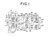
- the torque converter 1 comprises a pump impeller 3, a turbine runner 8, and a stator 9, in which the pump impeller 3 is driven by the crankshaft 4 to circulate the torque converter operation oil therein so as to transmit torque to the turbine runner 8 fixed on the input shaft 7.
- the torque is further transmitted by the input shaft 7 to a change-speed planetary gearing.
- the stator 9 is disposed on a sleeve 12 through a one-way clutch 10, the one-way clutch allowing the stator 9 to rotate in the same direction as the crankshaft 4, that is, in the direction indicated by an arrow in Fig. 1 (this rotation is referred to as forward rotation hereinafter), but not allowing it to rotate in the reverse direction (this rotation is referred to as reverse rotation hereinafter).
- the first planetary gear unit 110 comprises an internally toothed gear 117 fixed on the intermediate shaft 109, a sun gear 119 fixed on a hollow transmitting shaft 118, and more than one planetary pinions 120 capable of performing rotation and revolution simultaneously while meshing with the internally toothed gear 117 and sun gear 119 respectively, and a planetary pinion carrier 121 for supporting the planetary pinions 120 fixed on an output shaft 112, wherein the second planetary gear unit 111 comprises an internally toothed gear 122 fixed on the output shaft 112, a sun gear 123 fixed on the hollow transmitting shaft 118, and more than one planetary pinions 124 capable of performing rotation and revolution while meshing with the internally toothed gear 122 and sun gear 123 respectively, and a planetary pinion carrier 125 for supporting the planetary pinions 124.
- the front clutch 104 is operative to connect the input shaft 7 to be driven by the turbine runner 8 to the hollow transmitting shaft 118 integrally rotatable with both of the sun gears 119 and 123 through a drum 126
- the rear clutch 105 is operative to connect the input shaft 7 to the internally toothed gear 117 of the first planetary gear unit 110 through the intermediate shaft 109.
- the second brake 106 is operative to anchor both sun gears 119 and 123 by braking the drum 126 fixed on the hollow transmitting shaft 118
- the low reverse brake 107 is operative to anchor the pinion carrier 125 of the second planetary gear unit 111.
- the one-way brake 108 allows forward rotation of the pinion carrier 125 but not reverse rotation thereof.
- the first and second governor valve assemblies 113 and 114 are operatively connected to the output shaft 112 and produce governor pressure in response to the vehicle speed.
- the one-way brake 108 acts as a forward reaction brake to prevent the pinion carrier 125 from being rotated reversely by the sun gear 123, thus causing the forward rotation of the internally toothed gear 122 of the second planetary gear unit 111. Accordingly, the output shaft 112 which is rotatable with the internally toothed gear 122 rotates forwardly, thereby the first forward gear ratio being established.
- the power flow path through the input shaft 7 and rear clutch 105 up to the internally toothed gear 117 is the same as that for the first forward speed.
- the second brake 106 acts as a forward reaction brake to anchor the drum 126 for preventing the rotation of the sun gear 119.
- This causes the planetary pinions 120 to rotate, revolving simultaneously, around the anchored sun gear 119, and accordingly the planetary pinion carrier 121 and output shaft 112, which is rotatable with the pinion carrier 121, rotate at a faster speed than in the case of the first speed although with a certain reduction ratio, thereby the second forward gear ratio being established.
- the power on the input shaft 7 is transmitted partially through the rear clutch 105 to the internally toothed gear 117, while the remainder is transmitted through the front clutch 104 to the sun gear 119.
- the internally toothed gear 117 and sun gear 119 are interlocked and rotate forwardly, as a unit, together with both the pinion carrier 121 and output shaft 112 at the same rotational speed, thereby the third forward gear ratio being established.
- the input is fed to both the front clutch 104 and rear clutch 105 and the torque increase is not carried out by the planetary gears so that none act as a reaction brake in this state.
- planetary gearing arrangement illustrated in and described in connection with Fig. 1 is similar in construction to the planetary gearing arrangmenet disclosed in United States Pat. No. 2,856,794 issued to H. W. Simpson, on Oct. 21, 1958, and reference thereto may be made for a more complete description of the construction and operation of the transmission.
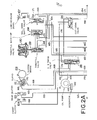
- Figs. 2A and 2B show a hydraulic control system of the above-described change speed transmission, which control system comprises an oil pump 13, a line pressure regulator valve 128, a pressure booster valve 129, a torque converter 1, a speed selector valve 130, a first governor valve 113, a second governor valve 114, a 1-2 shift valve 131, a 2-3 shift valve 132, a throttle pressure reducing valve 133, a cut-down valve 134, a second lock valve 135, a 2-3 timing valve 136, a solenoid down shift valve 137, a throttle back-up valve 138, a vacuum throttle valve 139, a vacuum diaphragm 140, a front clutch 104, a rear clutch 105, a second brake 106, a servo 141, a low-reverse brake 107, and oil pressure circuits.
- control system comprises an oil pump 13, a line pressure regulator valve 128, a pressure booster valve 129, a torque converter 1, a speed selector valve 130, a first
- the oil pump 13 is driven by a prime mover through the driving shaft 14 and the pump impeller P of the torque converter 1 for drawing oil from a reservoir 142 through a strainer 143, where harmful dust is removed, during all operating conditions of the prime mover to send the oil to a line pressure circuit 144.
- the oil is regulated by the line pressure regulator valve 128 and the thus regulated oil is transmitted to the torque converter 1 and speed selector valve 130.
- the hydraulic control system illustrated in Figs. 2A and 2B is similar in construction to the hydraulic control system disclosed in United States Pat. No. 3,710,652, issued to T. Miyazaki, on Jan. 16, 1973, and reference may be made for a more complete description of the construction and operation of the transmission.
- the line pressure regulator valve 128 comprises a spool 172 and a spring 173, in which, in addition to the spring 173, the throttle pressure in a circuit 165 and the line pressure in a circuit 156 act on the spool 172 via a spool 174 of the pressure booster valve 129 against the line pressure from a circuit 144 through an orifice 175 and the pressure from a circuit 176 both acting on upper areas of the spool 172.
- the torque converter operating oil pressure is introduced from the circuit 144 through the line pressure regulating valve 128 to a circuit 145 and, with a pressure maintaining valve 146, the level of this pressure is maintained within a certain range.
- the pressure maintaining valve 146 opens to permit the oil into a circuit 147 toward the rear lubricating part of the power transmitting mechanism.
- a relief valve 148 opens, resulting in a pressure drop.
- the lubricating oil is supplied from the circuit 145 through a front lubrication valve 149, as it is open, to the front lubricating part of the power transmitting mechanism.
- the speed selector valve 130 is a manually operable liquid direction switching valve and it comprises a spool 150, and is connected to a speed selector rod (not shown) through a linkage so that manipulating the speed selector rod into any desired one of the positions causes the spool 150 to change the passage of the line pressure circuit 144.
- Fig. 2B shows a condition of the speed selector valve when the spool takes up the N (neutral) position, wherein the line pressure circuit 144 is permitted to communicate with two ports d and e.
- the first and second governor valves 113 and 114 are in operative condition to produce a governor pressure while the automobile is moving forwardly.
- the speed selector valve 130 assumes either D, II or I position
- the oil pressure is fed from the line pressure circuit 144 to the second governor valve 114 through the port c of the speed selector valve 130.
- the governor pressure regulated by the second governor valve 114 is supplied to a circuit 157 leading to the first governor valve 113, and subsequently when the vehicle speed reaches a predetermined value, the spool 177 of the first governor valve 113 moves to a position wherein the circuit 157 communicates with a circuit 158, supplying the latter with the governor pressure regulated by the second governor valve 114.
- the governor pressure is also supplied to the circuit 158, thus acting on the respective end surfaces of the 1-2 shift valve 131, 2-3 shift valve and cut-down valve 134 against the respective springs which urge these valves toward respective lower half positions illustrated in Figs. 2A and 2B.
- a circuit 161 and a circuit 162 up to an apply side oil pressure chamber 169, the 1-2 shift valve 131 and second lock valve 35 are separately arranged, and a circuit 152 leads from the port b of the speed selector valve 130 to the second lock valve 135.
- the spool 150 of the speed selector valve 130 is moved to a position providing communication between the line pressure circuit 144 and ports a, b and c. From the port a, the oil pressure is transmitted through the circuit 151 to the second lock valve 135 to act on the lower end thereof for preventing the interruption of the circuits 161 and 162 which are permitted to communicate with each other when the spool 178 is pushed down, which spool is urged upwardly by a spring 179 and urged downwardly by the oil pressure transmitted thereto through the circuit 152 from the port b, while, the oil pressure at the port a is transmitted through an orifice 166 and a circuit 167 to the 2-3 shift valve 132.
- the oil pressure at the port c is transmitted through a circuit 153 to the second governor valve 114, rear clutch 105, and 1-2 shift valve 131, thereby the first forward gear ratio condition of the transmission being provided.
- the governor pressure in the circuit 158 urges the spool 160 to the 1-2 shift valve 131, which is urged to the right by the spring 159, to move to the left, for effecting an upshift from the first forward gear ratio to the second forward gear ratio, and, as a result, the circuit 153 is permitted to communicate with the circuit 161 thereby allowing the oil pressure to be transmitted through the second lock valve 135 to the apply side oil pressure chamber 169 of the servo 141 through a circuit 162 to apply the second brake 106, thus establishing the second forward gear ratio condition.
- the spool 160 is highly responsive to effect movement to the left with the necessary speed, so that the vehicle speed at which the upshift is made does not move toward the higher vehicle speed side from the designed speed level.
- the governor pressure in the circuit 158 urges the spool 164 of the 2-3 shift valve 132 to the left overcoming the spring 163, so that the circuit 167 is permitted to communicate with the circuit 168 directing the oil pressure, through the circuit 168, to the release-side oil pressure chamber 170 of the servo 141 so as to release the second brake. 106 and also to the front clutch 104 to engage the clutch 104, thus the third forward gear ratio condition is established.
- an unillustrated kickdown switch is closed or rendered on to energize a downshift solenoid (not illustrated) for the solenoid downshift valve 137.
- This movement of the spool 190 allows the kickdown circuit 180 to communicate with the line pressure circuit 144, thus allowing transmission of line pressure through the circuits 144 and 180 to the 1-2 shift valve 131 and the 2-3 shift valve 132 to act same in opposed relationship with the governor pressure.
- the spool 164 of the 2-3 shift valve is forced to move against the governor pressure toward the right hand position viewing in Fig. 2B by the above-mentioned line pressure, thus effecting a forced downshift from the thrid gear ratio to the second gear ratio when the vehicle speed falls in a predetermined range, thus providing a sufficient amount of acceleration force.
- the spool 160 of the 1-2 shift valve 131 is forced to move rightwardly against the governor pressure from the left hand position. This causes a forced downshift from the second gear ratio to the first gear ratio, thus providing a sufficient amount of acceleration force to meet the relatively heavy load.
- the spool 150 of the speed selector valve 130 is moved to a position providing communication between the line pressure circuit 144 and the ports b, c and d.
- the oil pressure at the port b is fed to the same place as in the case of D and the oil pressure at the port c is fed to the rear clutch to engage the latter.
- the spool 178 of the second lock valve 135 is pressed downwardly against the force of the spring 178 to assume a position in which the circuit 152 is permitted to communicate with the circuit 162, permitting the oil pressure to reach the apply side oil pressure chamber 169 of the servo 141 so as to effect application of the second brake 106, thereby the second forward gear ratio condition being established.
- the oil pressure at the port d is transmitted through the circuit 154 to the solenoid down shift valve 137 and throttle back-up valve 138.
- the second lock valve 135 cooperates with the speed selector valve 130 to lock the transmission in the second forward speed. If the speed selector lever is moved to I position (the first forward speed fixed), the line pressure circuit 144 is permitted to communicate with the ports c, d and e.
- the oil pressure at the port c reaches the rear clutch 105 to effect clutch engagement and the oil pressure at the port d reach the same places as in the case of II, whereas the oil pressure at the port e is transmitted through the circuit 155, 1-2 shift valve 131 and the circuit 171 to the low-reverse brake 107 so as to apply the low reverse brake 107 which, when applied, acts as a forward reaction brake, thereby rendering the transmission in the first forward gear ratio condition.
- the oil pressure at the port e is applied to the left end of the 1-2 shift valve assembly 131, through the circuit 171, urging to press the spool 160 to the right in cooperation with the spring 159, thereby locking the transmission in the first forward speed once a downshift is made thereto.
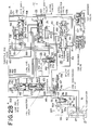
- the reference numeral 100 denotes a lock-up control system which comprises a lock-up control valve 30 and a lock-up solenoid 31.
- lock-up control valve 30, lock-up solenoid 31 and the torque converter 1 with a lock-up clutch 17 are specifically explained hereinafter.
- the pump impeller 3 of the torque converter 1 is connected via a torque converter cover 6 with a drive plate 5, which drive plate is connected to the engine crankshaft 4.
- the turbine runner 8 is splined to the input shaft 7 with a hub 18, and further the stator 9 is connected to the sleeve 12 via the one-way clutch 10.
- the torque converter 1 is enclosed by a converter housing 28 which is connected together with a pump housing 14 and a pump cover 11 to a transmission case 29.
- the pump housing 14 and pump cover 11 cooperate to define a chamber within which the oil pump 13 is accommodated, which pump is connected to the pump impeller-3 through a hollow shaft 52 driven by the engine.
- the hollow shaft 52 jackets therein the sleeve 12 to define an annular oil feed passage 50, and the sleeve 12 allows the input shaft 7 to extend therethrough and cooperate to define therebetween an oil discharge passage 51.
- the sleeve 12 is formed integrally with the pump cover 11.
- the lock-up clutch 17 has the following structure.
- a lock-up clutch piston 20 is fit around the hub 18 in an axially slidable manner, and this lock-up clutch piston is accommodated within the converter cover 6.
- the lock-up clutch piston 20 has an annular clutch facing 19 fixed to a surface thereof positioned opposite to the end wall of the torque converter cover 6, thereby to provide an arrangement wherein when this clutch facing contacts with the end wall of the converter cover 6, a lock-up clutch chamber 27 and a torque converter chamber 63 are defined on the opposite sides of the lock-up clutch piston 20.
- the lock-up clutch piston 20 is drivingly connected to the turbine runner 8 via a torsional damper 21.
- the torsional damper 21 is of the same type as that used in a dry-type clutch and the like and comprises a drive plate 23, torsional springs 24, rivets 25 and driven plates 26.
- An annular member 22 is welded to the lock-up clutch piston 20 and has its claws 22a drivingly engaging in cutouts 23a formed through the drive plate 23, and the driven plate 26 is attached to the turbine runner 8.
- the lock-up chamber 27 communicates with a lock-up passage 16 formed through the input shaft 7, which lock-up passage is operatively associated with said lock-up control system 100.
- the lock-up control valve 30 is provided with a spool 30a which when taking an illustrated upper half position in Fig. 3B, permits a port 30d to communicate with a port 30e and, when taking an illustrated lower half position, permits the port 30d to communicate with a drain port 30f.
- the port 30d communicates through a passage 56 with the lock-up passage 16
- the port 30e communicates through a branch passage 57 with a torque converter operating oil feed passage 50 as shown in Fig. 2B
- a chamber 30c communicates through a passage 53 with the rear clutch pressure passage 153 as shown in Fig. 2B.
- An orifice 54 is provided in the passage 53 at ° an intermediate portion, and the passage 53 has a branch passage 55 from a location between this orifice and the chamber 30c.
- the branch passage 55 has therein an orifice 58 and communicates with a drain port 59 and is associated with the solenoid valve 31 adapted to open and close the branch passage 55.
- the lock-up solenoid 31 has a plunger 31a which normally takes an illustrated left half position in Fig. 2B or Fig. 3B, but when the lock-up solenoid 31 is energized, projects to assume an illustrated right half position to close the branch passage 55.
- the lock-up control system 100 effects a lock-up control which will be later described in connection with its lock-up solenoid 31 that is operated by an electronic lock-up control unit 62 as generally shown in Fig. 4.
- the torque converter housing 28 has accommodated therein the torque converter 1 as previously described, while, the power transmitting gear train is accommodated within the transmission case 29 and the rear extension 60. Attached to the lower part of the transmission case 29 is a valve body 61 wherein the gear ratio hydraulic control system or circuit as shown in Figs. 2A and 2B is disposed.
- the electronic lock-up control unit 62 for the lock-up solenoid 31 is fed with an electric signal, that indicates the vehicle speed, from a vehicle speed sensor 64, an electric signal from a throttle sensor 66 operatively connected with the depression of an accelerator pedal 65 which signal indicates a throttle opening degree, and a 1-2 shift signal through an electric path 67 and a 2-3 shift signal through an electric path 68.
- the 1-2 shift signal and 2-3 shift signal which are fed through the electric paths 67 and 68 to the lock-up control unit 62 are produced by a 1-2 shift switch and a 2-3 shift switch which are respectively operated by the spool 160 of the 1-2 shift valve 131 and the spool 164 of the 2-3 shift valve 132 as shown in Fig. 2B.
- the 1-2 shift switch 69 and 2-3 shift switch 70 are respectively mounted within the shift valves 131 and 132 in such a manner as to be closed or opened in response to the positions of the corresponding spools 160 and 164.
- the spools 160 and 164 are used as movable contacts and stationary contacts 71 and 72 are mounted through insulators 71a and 72a are disposed at position opposite to right end surfaces, as illustrated, of the respective spools, thus allowing the spool 160 and the stationary contact 71 to cooperate with each other to form the 1-2 shift switch 69 and the spool 164 and stationary contact 72 to cooperate with each other to form the 2-3 shift switch 70.
- the lock-up control unit 62 is designed to effect on-off control of the lock-up solenoid 31 in a scheduled pattern in accordance with a result of arithmetric operation therein based upon the above-mentioned signals fed thereto, and for this purpose, the lock-up control unit 62 is constructed of a logic circuit as shown in Fig. 6 and performs the following functions.
- the spool 160 of the 1-2 shift valve 131 and the spool 164 of the 2-3 shift valve 132 assume positions as illustrated in Fig. 5A for the reason mentioned as above when the first gear ratio is selected, contacting the stationary contacts 71 and 72, thus closing the shift switches 69 and 70.
- the closing of the shift switches 69 and 70 allows the power supply 200 to be grounded through the resistors 201 and 202, thus rendering shift valve signals S 1v and S 2v to take L levels, respectively.
- the spool 160 of the 1-2 shift valve 131 assumes the position as illustrated in Fig.
- both of the spool 160 of the 1-2 shift valve 131 and the spool 164 of the 2-3 shift valve 132 take the position as illustrated in Fig. 5B after moving away to disengage from the stationary contacts 71 and 72, rendering both of the shift switches 69 and 70 open. This causes the shift switches 69 and 70 to change the shift valve signals S 1v and S 2v to H levels, respectively.
- a gear ratio decision circuit to which the above-mentioned shift valve signals S 1v and S 2v are fed and which is in the form of a logic circuit comprising NOR gates 204, 205 and 206 and NOT gates 207 and 208.
- the gear ratio decision circuit 203 generates a plurality of gear ratio signals S 1 , S 2' S 3 that indicate a corresponding gear ratios, viz., first gear ratio, second gear ratio and third gear ratio, selecatble by the lock-up type automatic transmission.
- the shift valve signals S 1v and S 2v are fed also to a gear shifting decision circuit 209 which gear shifting decision circuit comprises an edge trigger circuit 210 to detect a rise and a fall in the shift valve signal S 1v and an edge trigger circuit 211 to detect a rise and a fall in the shift valve signal S 2v , and a NAND gate 212.
- the edge trigger circuit 210 comprises a NOT gate 213, a resistor R 1 and a condensor C 1 which form a delay circuit, a NAND gate 214 for a rise detection, and an OR gate 215 for a fall detection.
- the edge trigger circuit 211 comprises a NOT gate 216, a delay circuit having a resistor R 2 and a condensor C 2 , a NAND gate 217, and an OR gate 218.
- the edge trigger circuits 210 and 211 feed a negative polarity pulse signal (the duration of the pulse width is determined by the above-mentioned delay circuit) to the corresponding input terminal of a NAND gate 212.
- the NAND gate 212 produce a positive polarity trigger pulse (designated by P 1 ) which is obtained after inversing the polarity of said pulse signal fed thereto, this pulse being fed to a timer 219 as a gear shifting signal S t .
- the timer 219 is designed such that, when the gear shifting signal S t is fed, the pulse width of it can be adjustably varied and thus a signal.
- P2 having a pulse width which can be adjusted as desired is produced.
- Designated by 220 is a load detector circuit and designated by 221 is a vehicle speed comparator circuit to which circuits the vehicle speed signal V from the vehicle speed sensor 64 is fed, and a throttle signal TH from the throttle sensor 66 is fed to the load detector circuit 220.
- the load detector circuit 220 comprises a reference acceleration memory and generating circuit 222, an actual acceleration generating circuit in the form of a differential circuit 223 and a comparator 224.
- the reference acceleration memory and generating circuit 222 has input terminals S 11 , S 12 and S 13 connected to the corresponding output terminals of said gear ratio decision circuit 203 (the corresponding ones are designated by the same reference numerals), and are fed with gear ratio signals S 1' S 2 and S 3 through these terminals, the vehicle speed signal V and the throttle signal TH, and use these operating condition indicative signals as address to determine a reference acceleration and generates a reference acceleration signal ⁇ ' that indicates the reference acceleration.
- the reference acceleration is a function of the vehicle speed, throttle opening degree and gear ratio.
- Various reference acceleration values are stored in the memory and generating circuit 222, each of which values represents acceleration of the automotive vehicle that is obtained when the automotive vehicle runs on a horizontal flat road surface at a given vehicle speed, with a given throttle opening and in a given gear ratio.
- the differential circuit 223 differentiates the vehicle speed signal V with respect to time for determining an actual acceleration and generating an actual acceleration signal (voltage) ⁇ that indicates the actual acceleration.
- the comparator 224 compares the actual acceleration signal ⁇ with the reference acceleration signal ⁇ ' and generates a L level signal (first command signal) when the actual acceleration signal ⁇ is greater than the reference acceleration signal ⁇ ', viz., when the desired degree of acceleration is obtained, while, it generates a H level signal (second command signal) when the actual acceleration signal ⁇ is smaller than the reference acceleration signal 0('.
- the load detector circuit 220 can decide whether the running load is relatively large or relatively small and allows the comparator 224 to produce a H level signal (second command signal) when the running load is great and to produce a L level signal (first command signal) when the running load is small.
- a hysteresis setting circuit is provided in association with the comparator 224 which comprises a transistor 238 and resistors 239 and 240.
- the transistor 238 has its base connected to an output terminal of the comparator 224, and the actual acceleration input terminal ( ⁇ ) of the comparator 224 is grounded through a series connected resistors 239 and 240 wherein a junction between the resistors 239 and 240 is grounded through a collector-emitter path of the transistor 238.
- the transistor 238 when the output signal of the comparator 224 takes a L level, the transistor 238 is rendered non-conductive, the actual acceleration signal a determined by the total of the resistors 239 and 240 is fed to the comparator 224 to allow the comparator 224 to produce a result of the above mentioned comparison operation of the actual acceleration signal ⁇ with the reference acceleration signal ⁇ '.
- the transistor 238 is rendered conductive, thus disabling the resistor 240, resulting in a reduction by the magnitude of its resistance in the actual acceleration signal to be fed to the comparator 224 as ⁇ - ⁇ , so that the comparator 224 compares this signal with a reference acceleration signal oC'. Accordingly, whenever the output level of the comparator 224 changes from a L level to a H level, the actual acceleration signal ⁇ is reduced by a predetermined value so that the comparator 224 changes its output level with a hysteresis ⁇ .
- the hysteresis setting circuit receives a H level signal from the comparator 224, viz., second command signal for reducing the actual acceleration signal upon appearance of the second command signal.
- the vehicle speed comparator circuit 221 comprises a low vehicle speed comparator circuit 225, a high vehicle speed comparator circuit 226, and OR gates 227 to 229.
- the low vehicle speed comparator circuit 225 is actuated or rendered operative upon appearance of a L level signal from the comparator 224, viz., first command signal
- the high vehicle speed comparator circuit 224 is actuated or rendered operative upon appearance of a H level signal from the comparator 204, viz., second command signal.
- the low vehicle speed comparator circuit 225 When the output of the comparator 224 takes a L level because of a small running load, the low vehicle speed comparator circuit 225 is rendered operative, while, when the output of the comparator 224 takes a H level because of a large running load, the high vehicle speed comparator circuit 226 is rendered operative.
- the low vehicle speed comparator circuit 225 compares the vehicle speed signal V fed thereto from the vehicle speed sensor 64 with a set of reference vehicle speeds V 1L , V 2L and V 3L that correspond to the gear ratios, respectively, and generating a plurality of patterns of signals that patterns indicate a corresponding plurality of lock-up ranges.
- the high vehicle speed comparator circuit 226 compares the vehicle speed signal V with a set of reference vehicle speeds V 1H' V 2H and V 3H that correspond to the gear ratios, respectively, and generates a plurality of patterns of signals that patterns indicate a corresponding plurality of lock-up ranges that are different from the lock-up ranges provided by the low vehicle speed comparator circuit 225.
- V 1L and V 1H correspond to a lock-up vehicle speed during operation in the first gear ratio under low running load operating condition and to a lock-up vehicle speed during operation in the first gear ratio under high running load operating condition, respectively
- V 2L and V 2H correspond to a lock-up vehicle speed during operation in second gear ratio under low running load operating condition and to a lock-up vehicle speed during operation in the second gear ratio under high running load operating condition, respectively
- V 3L and V 3H correspond to a lock-up vehicle speed during operation in third gear ratio under low running load operating condition and to a lock-up vehicle speed during operation in the third gear ratio under high running load operating condition, respectively.
- the low vehicle speed comparator circuit 225 changes a level of a lock-up permission signal S 1L from a corresponding gate of all to a H level when the vehicle speed signal V exceeds V 1L , also changes a level of a lock-up permission signal S 2L from a corresponding gate to a H level when the vehicle speed signal V exceeds V 2L , and further when the vehicle speed signal V exceeds V3L, also changes - a level of a lock-up permission signal S 3L from a corresponding gate to a H level.
- the high vehicle speed comparator circuit 226 changes a level of a lock-up permission signal S 1H from a corresponding gate to a H level when the vehicle speed signal V exceeds V 1H , also changes a level of a lock-up permission signal S 2H from a corresponding gate to a H level when the vehicle speed signal V exceeds V2H, and further when the vehicle speed signal V exceeds V3H, also changes a level of a lock-up permission signal S 3H to a H level.
- the OR gate 227 produces a lock-up signal S L1 for first gear ratio operation having a H level when one of the lock-up permission signals takes a H level, that is, when the vehicle speed V exceeds a lock-up vehicle speed V 1L or V 1H .
- the OR gate 228 produces a lock-up signal S L2 for second gear ratio operation, having a H level when either one of the signals takes a H level, that is, when the vehicle speed V exceeds a lock-up vehicle speed V 2L or V 2H .
- the OR gate 229 produces a lock-up signal for a third gear ratio operation having a H level when either one of the signals takes a H level, that is, when the vehicle speed V exceeds a lock-up vehicle speed V 3L or V 3H .
- the lock- up signals S L1 , S L2 and S L32 therefore, show a plurality of patterns as shown in the following Table that indicate lock-up ranges corresponding to the gear ratios, respectively.
- Designated by 230 is an actuating circuit for said lock-up solenoid 31 which circuit comprises three AND gates 231 to 233, a NOR gate 234, a NAND gate 235, a bias resistor 236 and a Darlington transistor 237.
- the AND gates 231 to 237 each having one of its input terminal fed with the corresponding one of said gear ratio signals S 1 to S 3 and the other input terminal thereof fed with the corresponding one of said lock-up signals S L1 , S L2 and S L3 .
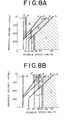
- the AND gate 231 produces a H level signal when the gear ratio signal S 1 takes a H level as the gear ratio is the first gear ratio and when the lock-up signal S L1 takes a H level as the vehicle speed is higher than the lock-up vehicle speed V 1L (during low running load operation) or the lock-up vehicle speed V 1H (during high running load operation), that is, during operation with low running load as illustrated by a range A in Fig. 8A or during operation with high running load illustrated by a range A' in Fig. 8B.
- the AND gate 232 produces a H level signal upon appearance of a gear ratio signal S 2 and a lock-up signal S L2 , that is, during operation with low running load as illustrated by a range B in Fig.
- the AND gate 233 produces a H level signal from a gear ratio signal S3 and a lock-up signal S L3' that is, during operation with low running load as illustrated by a range C in Fig. 8A or during operation with high running load as illustrated by a range C' in Fig. 8B.
- the signal causes a NOR gate to produce a L level signal.
- This L level signal is fed to one of input terminals of a NAND gate 235 as an actuating signal, and this NAND gate applies a H level signal, when a pulse signal P 2 is not fed to the other input terminal, that is, viz., when the gear shifting is not being carried out, to the base of the transistor 237 through a resistor 236, thus rendering this transistor conductive to actuate the lock-up solenoid 31 with the power supply +V.
- the lock-up solenoid 31 is energized to effect a lock-up as hereinafter described.
- the plunger 31a of the solenoid 31 takes a projected position as indicated by the right half in Fig. 3B, thus closing the branch passage 55, thus causing the torque converter 1 to take a lock-up state. That is, in this instance, the plunger 31a closes the branch passage 55, allowing the rear clutch pressure to be fed through the passage 53 to the chamber 30c to cause the spool 30a of the lock-up control valve 30 to take the illustrated upper half position from the illustrated lower half position in Fig. 3B, thus allowing the port 30d to connect with the drain port 30f.
- H level signals are not fed simultaneously to both two inputs of each of the AND gates 231 to 233 and thus three inputs to the NOR gate 234 all take L levels, so that the NOR gate continues to produce a H level, thus preventing the NAND gate from producing a H level.
- the lock-up solenoid 31 remains disengaged.
- the lock-up solenoid 31 is deenergized for a duration of gear shifting even upon operation within said lock-up ranges as described above. In the case that the lock-up solenoid 31 is deenergized, the plunger 31a is in the left half position illustrated in Fig.
- the torque converter interior pressure fed to the passage 57 is fed through the ports 30e and 30d, and passages 56 and 16 to the lock-up chamber 27, rendering the pressure within the lock-up chamber 27 to become substantially equal to the pressure within the converter chamber 63.
- This causes the lock-up clutch piston 20 to move rightwardly from the illustrated position in Fig. 3A, allowing the clutch facing 19 to disengage from the end wall of the converter cover 6, releasing the direct connection between the pump impeller 3 and turbine runner 8 to allow the torque converter 1 to transmit power in its converter state.
- the provision of the hysteresis setting circuit (238, 239, 240) reduces the actual acceleration signal ⁇ upon apperance of a H level signalfrom the comparator 224, viz., a second command signal which appears when thew actual acceleration signal ( ⁇ is smaller than the reference acceleration signal ⁇ ' .
- the H level signal is kept generated until the actual acceleration becomes greater than the actual acceleration which prevviously caused the comparator 224 to generate the H level signal. Therefore, frequent change in output signal level of the comparator 224 is prevented which otherwise would occur during operation with loads in the proximity of altering range of lock-up vehicle speed and result in the occurrence of chatterring of the lock-up solenoid 31, thus preventing the unnecessary shifting between the lock-up state and the torque converter state which would impair riding comfort.
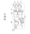
- the reference acceleration memory and generating circuit 222 of the load detector circuit 220 is designed to determine an appropriate reference acceleration ⁇ ' as against gear ratio signals S 1 , S 2' S 3 , vehicle speed signal V, and throttle signal TH by calculation or table look-up
- the reference acceleration memeory and generating circuit may be designed as shown in Fig. 7 wherein the reference acceleration is determined excluding the throttle signal TH.
- the precision of the reference acceleration ⁇ is relatively rough, but, it has an advantage that the circuit structure of the load detector circuit 220 becomes simplified.
- Chattering of the lock-up solenoid 31 during operation in the proximity of lock-up vehicle speeds mat be prevented by setting the lock-up release vehicle speeds lower than the lock-up vehicle speeds, as shown by a to c or by a' to c' shown in Figs. 8A and 8B to provide a hysteresis between upshifting into the lock-up state and downshifting from the lock-up state.
- a lock-up signal which causes energization of the lock-up solenoid 31, for example, the occurrence of a H level signal from the NAND gate 235, is fed back to the low vehicle speed comparator circuit 225 and high vehicle speed comparator circuit 226 as shown in Fig. 6, and the circuits 225 and 226 are designed so as to compare the vehicle speed signal with a set of relatively low vehicle speeds as compared to the reference vehicle speeds upon apperance of the lock-up signal.
Landscapes
- Engineering & Computer Science (AREA)
- General Engineering & Computer Science (AREA)
- Mechanical Engineering (AREA)
- Control Of Fluid Gearings (AREA)
Applications Claiming Priority (2)
| Application Number | Priority Date | Filing Date | Title |
|---|---|---|---|
| JP68948/80 | 1980-05-26 | ||
| JP6894880A JPS56167950A (en) | 1980-05-26 | 1980-05-26 | Lockup-type automatic transmission |
Publications (2)
| Publication Number | Publication Date |
|---|---|
| EP0040794A2 true EP0040794A2 (de) | 1981-12-02 |
| EP0040794A3 EP0040794A3 (de) | 1984-05-02 |
Family
ID=13388388
Family Applications (1)
| Application Number | Title | Priority Date | Filing Date |
|---|---|---|---|
| EP81103841A Withdrawn EP0040794A3 (de) | 1980-05-26 | 1981-05-19 | Automatisches Getriebe mit Überbrückungsschaltung |
Country Status (3)
| Country | Link |
|---|---|
| US (1) | US4471438A (de) |
| EP (1) | EP0040794A3 (de) |
| JP (1) | JPS56167950A (de) |
Cited By (4)
| Publication number | Priority date | Publication date | Assignee | Title |
|---|---|---|---|---|
| GB2122287A (en) * | 1982-05-17 | 1984-01-11 | Honda Motor Co Ltd | Torque converter lock-up clutch control |
| EP0195295A1 (de) * | 1985-03-18 | 1986-09-24 | Ford-Werke Aktiengesellschaft | Steuersystem für ein mehrgängiges Getriebe mit sperrbarem Drehmomentwandler |
| EP0200335A2 (de) * | 1985-04-03 | 1986-11-05 | Eaton Corporation | Strömungswandler mit Kupplungsanordnung zum Überbrücken und Unterbrechen für automatische mechanische Getriebe |
| US5211083A (en) * | 1990-12-28 | 1993-05-18 | Toyota Jidosha Kabushiki Kaisha | Hydraulic control apparatus for power transmitting system including belt-and-pulley type continuously variable transmission and torque converter equipped with lock-up clutch |
Families Citing this family (11)
| Publication number | Priority date | Publication date | Assignee | Title |
|---|---|---|---|---|
| JPS6049793B2 (ja) * | 1981-03-30 | 1985-11-05 | 日産自動車株式会社 | ロツクアツプ式自動変速機のロツクアツプ制御装置 |
| DE3218192A1 (de) * | 1982-05-14 | 1983-11-17 | Fichtel & Sachs Ag, 8720 Schweinfurt | Torsionsschwingungsdaempfer, insbesondere fuer drehmomentwandler |
| JPS59117950A (ja) * | 1982-12-25 | 1984-07-07 | Aisin Seiki Co Ltd | ロツクアツプ制御装置 |
| JPS59183150A (ja) * | 1983-03-31 | 1984-10-18 | Aisin Seiki Co Ltd | 直結クラツチ付自動変速機の制御装置 |
| JPH0694902B2 (ja) * | 1986-03-13 | 1994-11-24 | アイシン精機株式会社 | 自動変速機の制御装置 |
| JPH0818502B2 (ja) * | 1986-06-30 | 1996-02-28 | アイシン・エィ・ダブリュ株式会社 | 前後輪係合機構を備えた4輪駆動車 |
| GB2192160B (en) * | 1986-06-30 | 1990-04-25 | Aisin Warner | Four-wheel drive vehicle having antislip apparatus |
| EP0473204A3 (en) * | 1986-11-29 | 1993-03-31 | Aisin Seiki Kabushiki Kaisha | Vehicle speed control system for motor vehicle having an automatic transmission control system |
| US4843550A (en) * | 1987-02-09 | 1989-06-27 | Honda Giken Kogyo Kabushiki Kaisha | Method of indicating a shift operation of a manual gearbox of a vehicle |
| DE3823210C2 (de) * | 1988-07-08 | 1998-04-16 | Mannesmann Sachs Ag | Hydrodynamischer Drehmomentwandler mit Überbrückungskupplung und antriebsseitiger Lagerung des Kolbens |
| US9056603B2 (en) * | 2012-05-01 | 2015-06-16 | GM Global Technology Operations LLC | System and method for controlling engine torque to prevent driveline bump during a downshift when a throttle valve is closed |
Citations (10)
| Publication number | Priority date | Publication date | Assignee | Title |
|---|---|---|---|---|
| US3448640A (en) * | 1967-06-30 | 1969-06-10 | Gen Motors Corp | Electrical control for automatic transmission |
| US3805640A (en) * | 1972-09-08 | 1974-04-23 | Twin Disc Inc | Electronically controlled power transmission |
| US4081065A (en) * | 1976-12-23 | 1978-03-28 | Smyth Robert Ralston | Controlled power clutch |
| FR2375508A1 (fr) * | 1976-12-21 | 1978-07-21 | Deere & Co | Systeme de commande electronique pour mecanisme de changement de vitesses, notamment pour vehicules industriels |
| GB1536657A (en) * | 1975-11-14 | 1978-12-20 | Srm Hydromekanik Ab | Control system for a hydrodynamic torque converter |
| GB2012892A (en) * | 1978-01-24 | 1979-08-01 | Dana Corp | Mechanical Automatic Transmission |
| FR2422082A1 (fr) * | 1978-04-04 | 1979-11-02 | Nissan Motor | Systeme de commande de blocage a temporisation pour un convertisseur de couple |
| FR2422083A1 (fr) * | 1978-04-04 | 1979-11-02 | Nissan Motor | Systeme de commande de verrouillage pour un convertisseur de couple |
| FR2435639A1 (fr) * | 1978-09-05 | 1980-04-04 | Nissan Motor | Systeme de commande hydraulique pour convertisseur de couple hydrocinetique |
| FR2448076A1 (fr) * | 1979-02-02 | 1980-08-29 | Nissan Motor | Systeme de transmission automatique pourvu d'une fonction de frein moteur |
Family Cites Families (5)
| Publication number | Priority date | Publication date | Assignee | Title |
|---|---|---|---|---|
| DE2360212A1 (de) * | 1972-12-06 | 1974-06-12 | Sopromi Soc Proc Modern Inject | Verfahren zur steuerung einer brennkraftmaschine |
| DE2715999C2 (de) * | 1976-04-14 | 1984-01-19 | Kabushiki Kaisha Komatsu Seisakusho, Tokyo | Steuereinrichtung für ein automatisches Getriebe |
| US4056177A (en) * | 1976-05-07 | 1977-11-01 | S.R.M. Hydromekanik Aktiebolag | Simplified electronic pilot and remote control system for 11/2 stage transmission |
| ZA794292B (en) * | 1978-08-18 | 1981-03-25 | Srm Hydromekanik Ab | Hydromechanical transmissions |
| US4263822A (en) * | 1979-01-19 | 1981-04-28 | General Motors Corporation | Multirange transmissions |
-
1980
- 1980-05-26 JP JP6894880A patent/JPS56167950A/ja active Pending
-
1981
- 1981-05-19 EP EP81103841A patent/EP0040794A3/de not_active Withdrawn
- 1981-05-22 US US06/266,958 patent/US4471438A/en not_active Expired - Fee Related
Patent Citations (10)
| Publication number | Priority date | Publication date | Assignee | Title |
|---|---|---|---|---|
| US3448640A (en) * | 1967-06-30 | 1969-06-10 | Gen Motors Corp | Electrical control for automatic transmission |
| US3805640A (en) * | 1972-09-08 | 1974-04-23 | Twin Disc Inc | Electronically controlled power transmission |
| GB1536657A (en) * | 1975-11-14 | 1978-12-20 | Srm Hydromekanik Ab | Control system for a hydrodynamic torque converter |
| FR2375508A1 (fr) * | 1976-12-21 | 1978-07-21 | Deere & Co | Systeme de commande electronique pour mecanisme de changement de vitesses, notamment pour vehicules industriels |
| US4081065A (en) * | 1976-12-23 | 1978-03-28 | Smyth Robert Ralston | Controlled power clutch |
| GB2012892A (en) * | 1978-01-24 | 1979-08-01 | Dana Corp | Mechanical Automatic Transmission |
| FR2422082A1 (fr) * | 1978-04-04 | 1979-11-02 | Nissan Motor | Systeme de commande de blocage a temporisation pour un convertisseur de couple |
| FR2422083A1 (fr) * | 1978-04-04 | 1979-11-02 | Nissan Motor | Systeme de commande de verrouillage pour un convertisseur de couple |
| FR2435639A1 (fr) * | 1978-09-05 | 1980-04-04 | Nissan Motor | Systeme de commande hydraulique pour convertisseur de couple hydrocinetique |
| FR2448076A1 (fr) * | 1979-02-02 | 1980-08-29 | Nissan Motor | Systeme de transmission automatique pourvu d'une fonction de frein moteur |
Cited By (5)
| Publication number | Priority date | Publication date | Assignee | Title |
|---|---|---|---|---|
| GB2122287A (en) * | 1982-05-17 | 1984-01-11 | Honda Motor Co Ltd | Torque converter lock-up clutch control |
| EP0195295A1 (de) * | 1985-03-18 | 1986-09-24 | Ford-Werke Aktiengesellschaft | Steuersystem für ein mehrgängiges Getriebe mit sperrbarem Drehmomentwandler |
| EP0200335A2 (de) * | 1985-04-03 | 1986-11-05 | Eaton Corporation | Strömungswandler mit Kupplungsanordnung zum Überbrücken und Unterbrechen für automatische mechanische Getriebe |
| EP0200335A3 (en) * | 1985-04-03 | 1987-11-25 | Eaton Corporation | Torque converter disconnect & bypass clutch structure for automatic mechanical transmission |
| US5211083A (en) * | 1990-12-28 | 1993-05-18 | Toyota Jidosha Kabushiki Kaisha | Hydraulic control apparatus for power transmitting system including belt-and-pulley type continuously variable transmission and torque converter equipped with lock-up clutch |
Also Published As
| Publication number | Publication date |
|---|---|
| US4471438A (en) | 1984-09-11 |
| JPS56167950A (en) | 1981-12-23 |
| EP0040794A3 (de) | 1984-05-02 |
Similar Documents
| Publication | Publication Date | Title |
|---|---|---|
| US4457410A (en) | Lock-up control system for a lock-up type automatic transmission of an automotive vehicle having an engine | |
| US4431095A (en) | Lock-up type automatic transmission | |
| US4473882A (en) | Control method of and system for automatic transmission for automotive vehicle | |
| EP0044461B1 (de) | Überbrückungssteuerung für ein automatisches Getriebe mit Überbrückungskupplung | |
| EP0049476B1 (de) | Verfahren und Anlage zur Überbrückungssteuerung in einem automatischen Wechselgetriebe für Kraftfahrzeuge, die einen Motor mit Brennstoffabschliessvorrichtung aufweisen | |
| US4449618A (en) | Lock-up control system for lock-up type automatic transmission | |
| EP0041238B1 (de) | Steuerung für den Verbrennungsmotor eines Fahrzeuges mit überbrückbarem automatischen Getriebe | |
| US4350234A (en) | Automatic transmission system provided with a function of engine brake | |
| US4270636A (en) | Lock-up control system for a torque converter including a timing arrangement | |
| US4471438A (en) | Lock-up type automatic transmission | |
| US4369865A (en) | Lock-up control system for a torque converter | |
| US4582182A (en) | Lock-up control and method thereof | |
| US3688607A (en) | Transmission and control | |
| US5203235A (en) | Control system for automotive automatic transmission | |
| US3095755A (en) | Control circuit for a power transmission mechanism | |
| US3707890A (en) | Hydraulic control system for transmissions | |
| US4573375A (en) | Control system and method for automatic transmission for automotive vehicle | |
| US5364317A (en) | Control system for automotive automatic transmission | |
| JPS6346303B2 (de) | ||
| US3583259A (en) | Automatic transmission controls for use in an automotive vehicle | |
| JP2829031B2 (ja) | 車両用油圧装置の制御装置 | |
| JPS6318052B2 (de) | ||
| JP2956970B2 (ja) | 自動変速機の変速制御装置 | |
| JPH0121382B2 (de) | ||
| JPS5926660A (ja) | 自動変速機の油圧制御方法および装置 |
Legal Events
| Date | Code | Title | Description |
|---|---|---|---|
| PUAI | Public reference made under article 153(3) epc to a published international application that has entered the european phase |
Free format text: ORIGINAL CODE: 0009012 |
|
| AK | Designated contracting states |
Designated state(s): DE FR GB |
|
| PUAL | Search report despatched |
Free format text: ORIGINAL CODE: 0009013 |
|
| AK | Designated contracting states |
Designated state(s): DE FR GB |
|
| RHK1 | Main classification (correction) |
Ipc: B60K 41/22 |
|
| 17P | Request for examination filed |
Effective date: 19840509 |
|
| RAP1 | Party data changed (applicant data changed or rights of an application transferred) |
Owner name: NISSAN MOTOR CO., LTD. |
|
| STAA | Information on the status of an ep patent application or granted ep patent |
Free format text: STATUS: THE APPLICATION IS DEEMED TO BE WITHDRAWN |
|
| 18D | Application deemed to be withdrawn |
Effective date: 19860916 |
|
| RIN1 | Information on inventor provided before grant (corrected) |
Inventor name: HAMADA, HIDEO Inventor name: SUZUKI, TADASHI Inventor name: FUTAGI, MASAAKI Inventor name: MORITOMO, YOSHIRO Inventor name: SUGA, MASAAKI |