EP1270329B2 - Monitoring system - Google Patents
Monitoring system Download PDFInfo
- Publication number
- EP1270329B2 EP1270329B2 EP02013340.1A EP02013340A EP1270329B2 EP 1270329 B2 EP1270329 B2 EP 1270329B2 EP 02013340 A EP02013340 A EP 02013340A EP 1270329 B2 EP1270329 B2 EP 1270329B2
- Authority
- EP
- European Patent Office
- Prior art keywords
- image
- vehicle
- camera
- center
- images
- Prior art date
- Legal status (The legal status is an assumption and is not a legal conclusion. Google has not performed a legal analysis and makes no representation as to the accuracy of the status listed.)
- Expired - Lifetime
Links
- 238000012544 monitoring process Methods 0.000 title claims description 12
- 238000012545 processing Methods 0.000 claims abstract description 44
- 238000009434 installation Methods 0.000 description 35
- 238000010586 diagram Methods 0.000 description 14
- 238000013507 mapping Methods 0.000 description 11
- 238000013459 approach Methods 0.000 description 4
- 230000002194 synthesizing effect Effects 0.000 description 4
- 238000000034 method Methods 0.000 description 3
- 238000006243 chemical reaction Methods 0.000 description 2
- 239000007787 solid Substances 0.000 description 2
- 238000012546 transfer Methods 0.000 description 2
- 230000009466 transformation Effects 0.000 description 2
- 230000001131 transforming effect Effects 0.000 description 2
- 230000000007 visual effect Effects 0.000 description 2
- 238000004891 communication Methods 0.000 description 1
- 238000013461 design Methods 0.000 description 1
- 238000009499 grossing Methods 0.000 description 1
- 239000004973 liquid crystal related substance Substances 0.000 description 1
- 230000003287 optical effect Effects 0.000 description 1
Images


Classifications
-
- G—PHYSICS
- G06—COMPUTING; CALCULATING OR COUNTING
- G06T—IMAGE DATA PROCESSING OR GENERATION, IN GENERAL
- G06T15/00—3D [Three Dimensional] image rendering
- G06T15/10—Geometric effects
- G06T15/20—Perspective computation
-
- B—PERFORMING OPERATIONS; TRANSPORTING
- B60—VEHICLES IN GENERAL
- B60R—VEHICLES, VEHICLE FITTINGS, OR VEHICLE PARTS, NOT OTHERWISE PROVIDED FOR
- B60R1/00—Optical viewing arrangements; Real-time viewing arrangements for drivers or passengers using optical image capturing systems, e.g. cameras or video systems specially adapted for use in or on vehicles
- B60R1/20—Real-time viewing arrangements for drivers or passengers using optical image capturing systems, e.g. cameras or video systems specially adapted for use in or on vehicles
- B60R1/22—Real-time viewing arrangements for drivers or passengers using optical image capturing systems, e.g. cameras or video systems specially adapted for use in or on vehicles for viewing an area outside the vehicle, e.g. the exterior of the vehicle
- B60R1/23—Real-time viewing arrangements for drivers or passengers using optical image capturing systems, e.g. cameras or video systems specially adapted for use in or on vehicles for viewing an area outside the vehicle, e.g. the exterior of the vehicle with a predetermined field of view
- B60R1/26—Real-time viewing arrangements for drivers or passengers using optical image capturing systems, e.g. cameras or video systems specially adapted for use in or on vehicles for viewing an area outside the vehicle, e.g. the exterior of the vehicle with a predetermined field of view to the rear of the vehicle
-
- G—PHYSICS
- G06—COMPUTING; CALCULATING OR COUNTING
- G06T—IMAGE DATA PROCESSING OR GENERATION, IN GENERAL
- G06T5/00—Image enhancement or restoration
- G06T5/80—Geometric correction
-
- H—ELECTRICITY
- H04—ELECTRIC COMMUNICATION TECHNIQUE
- H04N—PICTORIAL COMMUNICATION, e.g. TELEVISION
- H04N7/00—Television systems
- H04N7/18—Closed-circuit television [CCTV] systems, i.e. systems in which the video signal is not broadcast
- H04N7/181—Closed-circuit television [CCTV] systems, i.e. systems in which the video signal is not broadcast for receiving images from a plurality of remote sources
-
- B—PERFORMING OPERATIONS; TRANSPORTING
- B60—VEHICLES IN GENERAL
- B60R—VEHICLES, VEHICLE FITTINGS, OR VEHICLE PARTS, NOT OTHERWISE PROVIDED FOR
- B60R2300/00—Details of viewing arrangements using cameras and displays, specially adapted for use in a vehicle
- B60R2300/20—Details of viewing arrangements using cameras and displays, specially adapted for use in a vehicle characterised by the type of display used
- B60R2300/207—Details of viewing arrangements using cameras and displays, specially adapted for use in a vehicle characterised by the type of display used using multi-purpose displays, e.g. camera image and navigation or video on same display
-
- B—PERFORMING OPERATIONS; TRANSPORTING
- B60—VEHICLES IN GENERAL
- B60R—VEHICLES, VEHICLE FITTINGS, OR VEHICLE PARTS, NOT OTHERWISE PROVIDED FOR
- B60R2300/00—Details of viewing arrangements using cameras and displays, specially adapted for use in a vehicle
- B60R2300/30—Details of viewing arrangements using cameras and displays, specially adapted for use in a vehicle characterised by the type of image processing
-
- B—PERFORMING OPERATIONS; TRANSPORTING
- B60—VEHICLES IN GENERAL
- B60R—VEHICLES, VEHICLE FITTINGS, OR VEHICLE PARTS, NOT OTHERWISE PROVIDED FOR
- B60R2300/00—Details of viewing arrangements using cameras and displays, specially adapted for use in a vehicle
- B60R2300/60—Details of viewing arrangements using cameras and displays, specially adapted for use in a vehicle characterised by monitoring and displaying vehicle exterior scenes from a transformed perspective
-
- B—PERFORMING OPERATIONS; TRANSPORTING
- B60—VEHICLES IN GENERAL
- B60R—VEHICLES, VEHICLE FITTINGS, OR VEHICLE PARTS, NOT OTHERWISE PROVIDED FOR
- B60R2300/00—Details of viewing arrangements using cameras and displays, specially adapted for use in a vehicle
- B60R2300/80—Details of viewing arrangements using cameras and displays, specially adapted for use in a vehicle characterised by the intended use of the viewing arrangement
- B60R2300/8066—Details of viewing arrangements using cameras and displays, specially adapted for use in a vehicle characterised by the intended use of the viewing arrangement for monitoring rearward traffic
Definitions
- the present invention relates to a technique for a monitoring system for providing safety driving environment by displaying a processed image of the sate around a vehicle taken by a camera installed on the vehicle.
- a system in which an image taken by a camera installed on a rear trunk room or the like of a vehicle is presented to a driver is conventionally known.
- the driver can be informed of the state in the rear of the vehicle.
- a system for supporting a parking operation in which not only a camera image but also possible travel loci of tires overlapping the camera image are present has recently been known.
- the driver can grasp the state ahead in a moving direction of the vehicle.
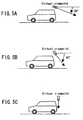
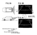
- FIG. 8A is a schematic diagram of a camera installation mode
- FIG. 8B shows an exemplified camera image obtained in the camera installation mode of FIG. 8A
- FIG. 8C shows an image obtained when the vehicle is moved straight backward by 25 cm from the position where the image of FIG. 8B is obtained.
- a dashed line A extending in the center indicates how the center of the vehicle behind approaches on the screen while the vehicle is moving straight backward
- solid lines B1 and B2 on the left and right hand sides indicate how the left and right corners of the vehicle behind approach on the screen while the vehicle is moving straight backward.
- the system is very useful for a user. This is because an object moving vertically on the screen can be identified as an object present on an extended center line of the vehicle, and hence, the moving direction of the vehicle can be grasped intuitively on the basis of the displayed image.
- a license plate, a rear windshield wiper, a locking mechanism for a trunk room, a spare tire and the like are generally placed around the center of the rear portion of a vehicle, and hence it may be difficult to secure a place for installing the camera.
- the position of the camera may be shifted so that a specified direction or region can be easily taken.
- the position of the camera may be shifted toward the passenger's seat side so that a larger region on the passenger's seat side where a driver is difficult to see from the driver's seat can be taken.
- FIG. 9A shows an exemplified camera image obtained in the camera installation mode of FIG. 2
- FIG. 9B shows an image obtained when the vehicle is moved straight backward by approximately 25 cm from the position where the image of FIG. 9A is taken.
- the dashed line A and the solid lines B1 and B2 have the same meanings as in FIG. 8B .
- FIG. 10A shows an exemplified camera image taken in the cameral installation mode of FIG. 6
- FIG. 10B shows an image obtained when the vehicle is moved straight backward by approximately 25 cm from the position where the image of FIG. 10A is taken.
- the dashed line A and the solid lines B1 and B2 have the same meanings as in FIGS. 8B and 9A .
- An object of the invention is providing a rear image which does not give an odd feeling to a user even when a camera for taking an image of a state behind a vehicle is installed in a position shifted from the rear center of the vehicle.
- the center line along the lengthwise direction of the vehicle substantially accords with the vertical center line of the displayed image. Therefore, when the vehicle is moved straight backward, an object present on the center line of the vehicle is moved vertically in substantially the center of the screen, and hence, this image does not give an odd feeling to a user.
- the rear image as if it were taken by a camera installed in the rear center of the vehicle and facing to the straight backward direction can be presented to the user.
- the restriction in the installation position and the facing direction of the camera of the monitoring system can be reduced, so as to increase the freedom in the camera installation.
- the image processing unit preferably performs lens more, the image processing unit preferably performs lens distortion correcting processing on the camera image.
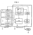
- FIG. 1 is a block diagram for showing the structure of the monitoring system of this invention.
- an image processing unit 20 receives, as inputs, a plurality of camera images output from camera means 10 including cameras 11 , so as to generate a new image by transforming and synthesizing the input camera images. This synthesized image is displayed by a display device 30 .
- the image processing unit 20 corresponds to an image processor of this invention.
- the display device 30 of this invention is typically a liquid crystal display, and may be another display device such as a plasma display. Also, the display device of this invention may be used also as a vehicle-install type GPS terminal display (namely, a display of what is called a car navigation system) or may be separately prepared.
- the camera means 10 is a color or monochrome digital camera typically including a solid state image sensor such as a CCD or a CMOS device.
- the camera means 10 may include a combination of a lens and a prism or a mirror so as to transfer incident light to the lens and the prism or the mirror through a predetermined optical path to a camera device disposed away from the camera means 10 .
- the image processing unit 20 transforms/synthesizes a camera image of at least one camera, so as to generate a synthesized image in which the input image is shifted laterally or a synthesized image as if it were vertically or obliquely looked down from above the vehicle.
- image transforming processing and synthesizing processing of partial images obtained by cutting out necessary areas of the transformed images including processing such as smoothing boundaries between the partial images (hereinafter referred to as the boundary processing) if a plurality of camera images are used).
- the structure of FIG. 1 includes a mapping table referring unit 21, and a mapping table is used for processing the camera images in one step.
- An image synthesizing unit 22 receives the camera images from the cameras 1 through N and processes these camera images.
- the processing 1 and 2 may be separately performed, or all or part of these processing may be performed in one step.
- the mapping table is included for performing the processing of the camera images in one step.
- mapping table means a table in which the corresponding relationships between pixels of a synthesized image and pixel data of the respective camera images are described, and is used for rapidly generating a synthesized image.
- mapping table is previously built through calculation using geometric conversion or manual operations, a desired synthesized image can be rapidly generated.
- mapping table is specifically stored in, for example, a ROM (including a writable erasable ROM such as an EEPROM) or a RAM.
- mapping data obtained through calculation by a processor included in the image processing unit may be written in a ROM or a RAM, or mapping table data provided as firmware may be written in a RAM or a ROM by using data transfer means such as a communication line and a disk drive.
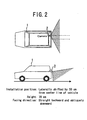
- Embodiment an example of processing employed in a camera installation mode in which a camera 2 facing to a straight backward direction of a vehicle 1 is installed in a position laterally shifted from the rear center of the vehicle 1 as shown in FIG. 2 will be described.
- the contents of this processing will now be described by using a camera image and a display screen mode resulting from the processing.
- FIG. 3A is a camera image taken in the camera 1 installation mode of FIG. 2 and FIG. 3B is a rear image obtained by shifting, in a leftward direction, merely a rectangular area RC1 surrounded with a broken line in the image of FIG. 3A for the purpose of overcoming difficulty in grasping the image due to the lateral shift of the camera position.
- the rectangular area RC1 is set so that the vertical center line of the rectangular area can substantially accord with an actual center line CL1 along the lengthwise direction of the vehicle 1 (indicated by a solid dashed line in the drawings).
- the vertical center line of the rear image on the monitor screen can be made to substantially accord with the center line CL1 of the vehicle merely by laterally shifting the camera image.
- the center line CL1 of the vehicle 1 can be made to move smoothly downward in the substantially center of the screen. Therefore, when a driver reverses the vehicle toward a target, it can be easily checked whether or not the vehicle is reversing toward the target on the basis of the movement in the center of the screen.
- a center line of the vehicle is drawn on the road behind the vehicle.
- the length of the line depends upon the rear visual range of the camera and a length of 5 m suffices.
- the state of the center line is taken by the camera, so as to calculate distances from the center of the image of average positions on the right and left hand sides of the center line. This distance corresponds to the extent of the image shift.
- the travel locus of the center of the vehicle is a straight line (as shown in FIG. 8B ).
- the travel locus is a curve due to the lens distortion. Since the lens distortion is larger in an area farther from the center of the image, the curvature is larger as the shift of the installation position is larger. This curvature cannot be corrected merely by the lateral shift of the image.
- the lens distortion can be corrected by two-dimensional image transformation for moving positions of respective pixels of the image in accordance with the characteristic of the lens of the camera. For example, a square lattice pattern is previously taken by a camera so as to measure how the respective lattice points are transformed by the lens distortion, and this transformation is reversely corrected. Thus, the lens distortion can be corrected.
- FIG. 3C shows an image obtained from the image of FIG. 3A by correcting the lens distortion and correcting the positional shift of the camera through the lateral shift of the image.
- FIG. 3C shows an image obtained from the image of FIG. 3A by correcting the lens distortion and correcting the positional shift of the camera through the lateral shift of the image.
- an object present on the center line of the vehicle moves straight in the vertical direction in the center of the screen. Therefore, the moving direction of the vehicle and the positional relationship with an object around the vehicle can be more easily grasped.
- Illustrative example corresponds to an aspect in which a user-friendly image can be generated even in these camera installation modes. Now, the contents of processing of illustrative example will be described by using a camera image and a display screen mode resulting from the processing.
- the installation position of the camera alone is largely shifted from the center of the vehicle as shown in FIG. 2 .
- FIG. 4A shows camera images taken in the camera installation mode of FIG. 2
- FIGS. 4B through 4D show synthesized images as if they were seen from a virtual viewpoint obtained by subjecting the images of FIG. 4A to viewpoint converting processing for the purpose of overcoming difficulty in grasping the image due to the lateral shift of the camera position
- FIGS. 5A through 5C show the virtual viewpoints employed in the rear images of FIGS. 4B through 4D , respectively.
- the virtual viewpoint is in a position above the rear center of the vehicle and the camera faces to a straight backward direction of the vehicle at an angle of 30 degrees against the road surface in FIG.
- the virtual viewpoint is in a position above the rear center of the vehicle and the camera faces to a straight backward direction of the vehicle at an angle of 60 degrees against the road surface in FIG. 5B ; and the virtual viewpoint is in a position above the rear center of the vehicle and the camera faces straight downward in FIG. 5C .
- Each of the images of FIGS. 4B through 4D is processed through the virtual viewpoint converting processing so that the center line CL1 along the lengthwise direction of the vehicle on the road surface can accord with the vertical center line of the screen.
- an object on the center line CL1 of the vehicle moves straight downward in the vertical direction on the screen.
- the virtual viewpoint can be given an angle of depression independently of the angle of depression of the actually used camera. Therefore, the positional relationship with a feature on a road surface (such as a white line) can be more easily grasped by generating an image as if it were looked down from further above.
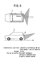
- the installation position of the camera is largely shifted from the center of the vehicle and the camera faces to a direction slightly oblique to the straight backward direction of the vehicle as shown in FIG. 6 .
- FIG. 7A shows camera images taken in the camera installation mode of FIG. 6
- FIGS. 7B through 7D show synthesized images as if they were seen from a virtual viewpoint obtained by subjecting the images of FIG. 7A to the viewpoint converting processing for the purpose of overcoming difficulty in grasping the image due to the lateral shift of the camera position.
- the virtual viewpoints employed in the images of FIGS. 7B through 7D also correspond to those shown in FIGS. 5A through 5C , respectively.
- a road surface area such as a white line is substantially the same as that in the image obtained through the virtual viewpoint converting processing of the camera image taken in the first camera installation mode.
- FIGS. 11A trough 11D exemplify a case where the image processing according to the Embodiment is applied in the camera installation mode shown in FIG. 6 .
- FIG. 11B is an image obtained by shifting, in a leftward direction, the rectangular area in the image of FIG. 11A , which is an original camera image
- FIG. 11C is an image obtained by correcting the lens distortion of the image of FIG. 11B
- FIG. 11D is an image obtained by rotating the image of FIG. 11C so as to conform the direction of the center line with the perpendicular direction of the image.
- the image remains unbalanced on the right and left sides, which might be the limit in the two-dimensional image processing.
- a more natural image as shown in FIGS. 7D can be generated by the virtual viewpoint conversion.
- mapping table corresponding to an image to be displayed may be provided or a mapping table may be automatically built in accordance with the situation.
- a vehicle of this invention includes, an ordinary car, a light car, a truck, a bus and the like.
- the present invention is very effective in a vehicle in which a camera cannot be installed in the rear center because of a spare tire or the like placed in the rear or for reasons in the design.
- a special vehicle such as a crane truck and an excavator may be a vehicle of this invention as far as the technical idea of the invention is applicable.
- a rear image as if it were taken by a camera installed in the rear center and facing to a straight backward direction can be presented to a user.
- the restriction in the installation position and the facing direction of the camera of the monitoring system can be reduced, so as to increase the freedom in the camera installation.
Landscapes
- Engineering & Computer Science (AREA)
- Multimedia (AREA)
- Theoretical Computer Science (AREA)
- Physics & Mathematics (AREA)
- General Physics & Mathematics (AREA)
- Computer Graphics (AREA)
- Geometry (AREA)
- Computing Systems (AREA)
- Signal Processing (AREA)
- Mechanical Engineering (AREA)
- Closed-Circuit Television Systems (AREA)
- Image Processing (AREA)
- Processing Or Creating Images (AREA)
- Image Analysis (AREA)
- Iron Core Of Rotating Electric Machines (AREA)
Applications Claiming Priority (2)
| Application Number | Priority Date | Filing Date | Title |
|---|---|---|---|
| JP2001182741 | 2001-06-18 | ||
| JP2001182741A JP4512293B2 (ja) | 2001-06-18 | 2001-06-18 | 監視システムおよび監視方法 |
Publications (4)
| Publication Number | Publication Date |
|---|---|
| EP1270329A2 EP1270329A2 (en) | 2003-01-02 |
| EP1270329A3 EP1270329A3 (en) | 2003-12-17 |
| EP1270329B1 EP1270329B1 (en) | 2009-09-16 |
| EP1270329B2 true EP1270329B2 (en) | 2016-11-23 |
Family
ID=19022775
Family Applications (1)
| Application Number | Title | Priority Date | Filing Date |
|---|---|---|---|
| EP02013340.1A Expired - Lifetime EP1270329B2 (en) | 2001-06-18 | 2002-06-18 | Monitoring system |
Country Status (5)
| Country | Link |
|---|---|
| US (3) | US20020191078A1 (ja) |
| EP (1) | EP1270329B2 (ja) |
| JP (1) | JP4512293B2 (ja) |
| AT (1) | ATE442976T1 (ja) |
| DE (1) | DE60233705D1 (ja) |
Families Citing this family (32)
| Publication number | Priority date | Publication date | Assignee | Title |
|---|---|---|---|---|
| JP4956880B2 (ja) * | 2001-09-27 | 2012-06-20 | アイシン精機株式会社 | 車両用監視装置 |
| US7110021B2 (en) * | 2002-05-31 | 2006-09-19 | Matsushita Electric Industrial Co., Ltd. | Vehicle surroundings monitoring device, and image production method/program |
| US7272482B2 (en) * | 2002-09-30 | 2007-09-18 | Nissan Motor Co., Ltd. | Preceding-vehicle following control system |
| JP4332028B2 (ja) * | 2003-12-25 | 2009-09-16 | キャタピラージャパン株式会社 | 表示器制御システム |
| JP4380550B2 (ja) * | 2004-03-31 | 2009-12-09 | 株式会社デンソー | 車載用撮影装置 |
| JP2006129149A (ja) * | 2004-10-29 | 2006-05-18 | Auto Network Gijutsu Kenkyusho:Kk | 車両周辺視認装置 |
| EP1662440A1 (en) * | 2004-11-30 | 2006-05-31 | IEE INTERNATIONAL ELECTRONICS & ENGINEERING S.A. | Method for determining the position of an object from a digital image |
| WO2006087993A1 (ja) * | 2005-02-15 | 2006-08-24 | Matsushita Electric Industrial Co., Ltd. | 周辺監視装置および周辺監視方法 |
| JP4680670B2 (ja) * | 2005-05-12 | 2011-05-11 | 株式会社バンダイナムコゲームス | プログラム、情報記憶媒体及び画像生成システム |
| JP2006318388A (ja) * | 2005-05-16 | 2006-11-24 | Namco Bandai Games Inc | プログラム、情報記憶媒体及び画像生成システム |
| JP4760831B2 (ja) * | 2005-08-02 | 2011-08-31 | 日産自動車株式会社 | 車両周囲監視装置及び車両周囲監視方法 |
| US20090128630A1 (en) * | 2006-07-06 | 2009-05-21 | Nissan Motor Co., Ltd. | Vehicle image display system and image display method |
| JP4977556B2 (ja) | 2006-10-11 | 2012-07-18 | ルネサスエレクトロニクス株式会社 | 半導体集積回路装置および描画処理表示システム |
| JP4853712B2 (ja) * | 2006-12-28 | 2012-01-11 | アイシン精機株式会社 | 駐車支援装置 |
| WO2008117386A1 (ja) * | 2007-03-23 | 2008-10-02 | Pioneer Corporation | 車両用画像処理装置及び車両用画像処理プログラム |
| KR100882875B1 (ko) | 2007-12-18 | 2009-02-10 | 주식회사 현대오토넷 | 영상 위치 변환을 위한 차량 후방 영상 표시 장치 및 방법 |
| JP4874280B2 (ja) * | 2008-03-19 | 2012-02-15 | 三洋電機株式会社 | 画像処理装置及び方法、運転支援システム、車両 |
| KR20120053713A (ko) * | 2010-11-18 | 2012-05-29 | 에스엘 주식회사 | 차량용 카메라의 제어 장치 및 방법 |
| JP5447490B2 (ja) * | 2011-11-18 | 2014-03-19 | アイシン精機株式会社 | 車両用監視装置 |
| CN103847638A (zh) * | 2012-11-28 | 2014-06-11 | 德尔福电子(苏州)有限公司 | 车轮方向显示装置 |
| US9052393B2 (en) | 2013-01-18 | 2015-06-09 | Caterpillar Inc. | Object recognition system having radar and camera input |
| US9167214B2 (en) | 2013-01-18 | 2015-10-20 | Caterpillar Inc. | Image processing system using unified images |
| US9071732B2 (en) * | 2013-03-15 | 2015-06-30 | Tolo, Inc. | Distortion correcting sensors for diagonal collection of oblique imagery |
| JP5999043B2 (ja) * | 2013-07-26 | 2016-09-28 | 株式会社デンソー | 車両周辺監視装置およびプログラム |
| JP6036601B2 (ja) * | 2013-08-09 | 2016-11-30 | 株式会社デンソー | 画像処理装置及び画像処理方法 |
| US20150175088A1 (en) * | 2013-12-23 | 2015-06-25 | Teddy Chang | Extendable Surround Image Capture System for Vehicles |
| WO2016076400A1 (ja) | 2014-11-13 | 2016-05-19 | オリンパス株式会社 | 較正装置、較正方法、光学装置、撮影装置、投影装置、計測システムおよび計測方法 |
| JP7054803B2 (ja) | 2017-07-21 | 2022-04-15 | パナソニックIpマネジメント株式会社 | カメラパラメタセット算出装置、カメラパラメタセット算出方法及びプログラム |
| JP6958117B2 (ja) * | 2017-08-29 | 2021-11-02 | 株式会社アイシン | 駐車支援装置 |
| EP3462550B1 (en) * | 2017-10-02 | 2021-01-27 | Hosiden Corporation | Connector module and onboard camera using the same |
| CN112019816A (zh) * | 2020-09-03 | 2020-12-01 | 中车青岛四方车辆研究所有限公司 | 列车流媒体传输装置及视频监控系统 |
| JP2022168699A (ja) | 2021-04-26 | 2022-11-08 | キヤノン株式会社 | 移動体、撮像システム、および撮像装置 |
Family Cites Families (32)
| Publication number | Priority date | Publication date | Assignee | Title |
|---|---|---|---|---|
| JPH0399952A (ja) | 1989-09-12 | 1991-04-25 | Nissan Motor Co Ltd | 車両用周囲状況モニタ |
| JPH03201110A (ja) * | 1989-12-28 | 1991-09-03 | Toyota Central Res & Dev Lab Inc | 自律走行車の位置方位検出装置 |
| FR2673499B1 (fr) * | 1991-03-01 | 1995-08-04 | Renault | Dispositif de retrovision par camera pour vehicule automobile. |
| US5329310A (en) * | 1992-06-30 | 1994-07-12 | The Walt Disney Company | Method and apparatus for controlling distortion of a projected image |
| JP3374570B2 (ja) * | 1995-01-31 | 2003-02-04 | いすゞ自動車株式会社 | 車線逸脱警報装置 |
| US6498620B2 (en) * | 1993-02-26 | 2002-12-24 | Donnelly Corporation | Vision system for a vehicle including an image capture device and a display system having a long focal length |
| US5670935A (en) * | 1993-02-26 | 1997-09-23 | Donnelly Corporation | Rearview vision system for vehicle including panoramic view |
| US5883739A (en) * | 1993-10-04 | 1999-03-16 | Honda Giken Kogyo Kabushiki Kaisha | Information display device for vehicle |
| DE4336288C1 (de) * | 1993-10-25 | 1995-03-30 | Daimler Benz Ag | Einrichtung zur Überwachung des Rück- bzw. Frontraumes eines einparkenden Kraftfahrzeugs |
| JPH08147497A (ja) * | 1994-11-25 | 1996-06-07 | Canon Inc | 画像処理方法及びその装置 |
| JPH08234701A (ja) * | 1995-02-28 | 1996-09-13 | Sony Corp | 映像表示装置 |
| JPH10257482A (ja) * | 1997-03-13 | 1998-09-25 | Nissan Motor Co Ltd | 車両周辺状況表示装置 |
| JPH1166488A (ja) * | 1997-08-21 | 1999-03-09 | Honda Motor Co Ltd | 白線認識装置 |
| JP3511892B2 (ja) * | 1998-05-25 | 2004-03-29 | 日産自動車株式会社 | 車両用周囲モニタ装置 |
| US6529640B1 (en) * | 1998-06-09 | 2003-03-04 | Nikon Corporation | Image processing apparatus |
| FR2780230B1 (fr) * | 1998-06-18 | 2000-08-25 | Renault | Dispositif de retrovision principale pour vehicule automobile |
| EP2267656A3 (en) | 1998-07-31 | 2012-09-26 | Panasonic Corporation | Image displaying apparatus und image displaying method |
| EP1004916A1 (en) * | 1998-11-25 | 2000-05-31 | Donnelly Corporation | Wide angle imaging system for vehicle |
| JP2000161915A (ja) * | 1998-11-26 | 2000-06-16 | Matsushita Electric Ind Co Ltd | 車両用単カメラ立体視システム |
| US6184781B1 (en) * | 1999-02-02 | 2001-02-06 | Intel Corporation | Rear looking vision system |
| EP1179958B1 (en) | 1999-04-16 | 2012-08-08 | Panasonic Corporation | Image processing device and monitoring system |
| JP3298851B2 (ja) * | 1999-08-18 | 2002-07-08 | 松下電器産業株式会社 | 多機能車載カメラシステムと多機能車載カメラの画像表示方法 |
| JP3624769B2 (ja) | 1999-09-30 | 2005-03-02 | 株式会社豊田自動織機 | 車両後方監視装置用画像変換装置 |
| US6813371B2 (en) * | 1999-12-24 | 2004-11-02 | Aisin Seiki Kabushiki Kaisha | On-vehicle camera calibration device |
| EP1148461B1 (en) * | 2000-04-05 | 2004-09-22 | Matsushita Electric Industrial Co., Ltd. | Driving operation assisting method and system |
| US6734896B2 (en) * | 2000-04-28 | 2004-05-11 | Matsushita Electric Industrial Co., Ltd. | Image processor and monitoring system |
| JP3599639B2 (ja) * | 2000-05-26 | 2004-12-08 | 松下電器産業株式会社 | 画像処理装置 |
| JP2002359839A (ja) * | 2001-03-29 | 2002-12-13 | Matsushita Electric Ind Co Ltd | リアビューカメラの画像表示方法及びその装置 |
| AU2002308651A1 (en) * | 2001-05-04 | 2002-11-18 | Leberl, Franz, W. | Digital camera for and method of obtaining overlapping images |
| JP4760831B2 (ja) * | 2005-08-02 | 2011-08-31 | 日産自動車株式会社 | 車両周囲監視装置及び車両周囲監視方法 |
| EP2674323B1 (en) * | 2007-04-30 | 2018-07-11 | Mobileye Vision Technologies Ltd. | Rear obstruction detection |
| JP4595976B2 (ja) * | 2007-08-28 | 2010-12-08 | 株式会社デンソー | 映像処理装置及びカメラ |
-
2001
- 2001-06-18 JP JP2001182741A patent/JP4512293B2/ja not_active Expired - Lifetime
-
2002
- 2002-06-17 US US10/173,316 patent/US20020191078A1/en not_active Abandoned
- 2002-06-18 AT AT02013340T patent/ATE442976T1/de not_active IP Right Cessation
- 2002-06-18 EP EP02013340.1A patent/EP1270329B2/en not_active Expired - Lifetime
- 2002-06-18 DE DE60233705T patent/DE60233705D1/de not_active Expired - Lifetime
-
2009
- 2009-02-12 US US12/369,979 patent/US8201199B2/en not_active Expired - Fee Related
-
2012
- 2012-05-10 US US13/468,661 patent/US20120218413A1/en not_active Abandoned
Also Published As
| Publication number | Publication date |
|---|---|
| EP1270329A3 (en) | 2003-12-17 |
| EP1270329B1 (en) | 2009-09-16 |
| JP2002374523A (ja) | 2002-12-26 |
| JP4512293B2 (ja) | 2010-07-28 |
| ATE442976T1 (de) | 2009-10-15 |
| US20120218413A1 (en) | 2012-08-30 |
| EP1270329A2 (en) | 2003-01-02 |
| US20090174775A1 (en) | 2009-07-09 |
| DE60233705D1 (de) | 2009-10-29 |
| US20020191078A1 (en) | 2002-12-19 |
| US8201199B2 (en) | 2012-06-12 |
Similar Documents
| Publication | Publication Date | Title |
|---|---|---|
| EP1270329B2 (en) | Monitoring system | |
| US7006127B2 (en) | Driving aiding system | |
| JP4766841B2 (ja) | 車両に搭載されるカメラ装置及び車両周辺監視装置 | |
| US7076345B2 (en) | Parking assist system | |
| US7295229B2 (en) | Surround surveillance apparatus for mobile body | |
| US7266219B2 (en) | Monitoring system | |
| US7365653B2 (en) | Driving support system | |
| US20020075387A1 (en) | Arrangement and process for monitoring the surrounding area of an automobile | |
| JP4765649B2 (ja) | 車両用映像処理装置、車両周囲監視システム並びに映像処理方法 | |
| JP2005110202A (ja) | カメラ装置及び車両周辺監視装置 | |
| JP2005311868A (ja) | 車両周辺視認装置 | |
| JP5036891B2 (ja) | 車両に搭載されるカメラ装置及び車両周辺監視装置 | |
| JP2001163132A (ja) | 車両後方監視装置用画像変換装置 | |
| WO2013118705A1 (ja) | 運搬車両の周囲監視装置 | |
| JP2006050246A (ja) | 車両周辺視認装置 | |
| JP3753681B2 (ja) | 監視システム | |
| KR101510655B1 (ko) | 주변 영상 생성 방법 및 장치 | |
| EP2757768A1 (en) | Camera calibration device, camera, and camera calibration method | |
| EP3772719B1 (en) | Image processing apparatus, image processing method, and image processing program | |
| WO2016129552A1 (ja) | カメラパラメータ調整装置 | |
| JP4499319B2 (ja) | 運転支援装置、運転支援方法および運転ガイドデータ作成方法 | |
| KR101861523B1 (ko) | 차량 운전 보조 장치 및 방법 | |
| JP2011114536A (ja) | 車両周辺画像提供装置 | |
| JP2021512536A (ja) | 自動車用のカメラ・モニターシステムを運転する方法および装置 | |
| JP7301476B2 (ja) | 画像処理装置 |
Legal Events
| Date | Code | Title | Description |
|---|---|---|---|
| PUAI | Public reference made under article 153(3) epc to a published international application that has entered the european phase |
Free format text: ORIGINAL CODE: 0009012 |
|
| AK | Designated contracting states |
Kind code of ref document: A2 Designated state(s): AT BE CH CY DE DK ES FI FR GB GR IE IT LI LU MC NL PT SE TR |
|
| AX | Request for extension of the european patent |
Free format text: AL;LT;LV;MK;RO;SI |
|
| PUAL | Search report despatched |
Free format text: ORIGINAL CODE: 0009013 |
|
| AK | Designated contracting states |
Kind code of ref document: A3 Designated state(s): AT BE CH CY DE DK ES FI FR GB GR IE IT LI LU MC NL PT SE TR |
|
| AX | Request for extension of the european patent |
Extension state: AL LT LV MK RO SI |
|
| RIC1 | Information provided on ipc code assigned before grant |
Ipc: 7H 04N 7/18 B Ipc: 7G 06T 3/00 B Ipc: 7B 60Q 1/48 A |
|
| 17P | Request for examination filed |
Effective date: 20040105 |
|
| AKX | Designation fees paid |
Designated state(s): AT BE CH CY DE DK ES FI FR GB GR IE IT LI LU MC NL PT SE TR |
|
| AXX | Extension fees paid |
Extension state: AL Payment date: 20040105 Extension state: LT Payment date: 20040105 Extension state: LV Payment date: 20040105 Extension state: MK Payment date: 20040105 Extension state: SI Payment date: 20040105 Extension state: RO Payment date: 20040105 |
|
| RAP1 | Party data changed (applicant data changed or rights of an application transferred) |
Owner name: PANASONIC CORPORATION |
|
| GRAP | Despatch of communication of intention to grant a patent |
Free format text: ORIGINAL CODE: EPIDOSNIGR1 |
|
| GRAS | Grant fee paid |
Free format text: ORIGINAL CODE: EPIDOSNIGR3 |
|
| GRAA | (expected) grant |
Free format text: ORIGINAL CODE: 0009210 |
|
| AK | Designated contracting states |
Kind code of ref document: B1 Designated state(s): AT BE CH CY DE DK ES FI FR GB GR IE IT LI LU MC NL PT SE TR |
|
| AX | Request for extension of the european patent |
Extension state: AL LT LV MK RO SI |
|
| REG | Reference to a national code |
Ref country code: GB Ref legal event code: FG4D |
|
| REG | Reference to a national code |
Ref country code: CH Ref legal event code: EP |
|
| REG | Reference to a national code |
Ref country code: IE Ref legal event code: FG4D |
|
| REF | Corresponds to: |
Ref document number: 60233705 Country of ref document: DE Date of ref document: 20091029 Kind code of ref document: P |
|
| PG25 | Lapsed in a contracting state [announced via postgrant information from national office to epo] |
Ref country code: FI Free format text: LAPSE BECAUSE OF FAILURE TO SUBMIT A TRANSLATION OF THE DESCRIPTION OR TO PAY THE FEE WITHIN THE PRESCRIBED TIME-LIMIT Effective date: 20090916 Ref country code: SE Free format text: LAPSE BECAUSE OF FAILURE TO SUBMIT A TRANSLATION OF THE DESCRIPTION OR TO PAY THE FEE WITHIN THE PRESCRIBED TIME-LIMIT Effective date: 20090916 |
|
| LTIE | Lt: invalidation of european patent or patent extension |
Effective date: 20090916 |
|
| PG25 | Lapsed in a contracting state [announced via postgrant information from national office to epo] |
Ref country code: NL Free format text: LAPSE BECAUSE OF FAILURE TO SUBMIT A TRANSLATION OF THE DESCRIPTION OR TO PAY THE FEE WITHIN THE PRESCRIBED TIME-LIMIT Effective date: 20090916 |
|
| NLV1 | Nl: lapsed or annulled due to failure to fulfill the requirements of art. 29p and 29m of the patents act | ||
| PG25 | Lapsed in a contracting state [announced via postgrant information from national office to epo] |
Ref country code: CY Free format text: LAPSE BECAUSE OF FAILURE TO SUBMIT A TRANSLATION OF THE DESCRIPTION OR TO PAY THE FEE WITHIN THE PRESCRIBED TIME-LIMIT Effective date: 20090916 |
|
| PG25 | Lapsed in a contracting state [announced via postgrant information from national office to epo] |
Ref country code: PT Free format text: LAPSE BECAUSE OF FAILURE TO SUBMIT A TRANSLATION OF THE DESCRIPTION OR TO PAY THE FEE WITHIN THE PRESCRIBED TIME-LIMIT Effective date: 20100118 Ref country code: ES Free format text: LAPSE BECAUSE OF FAILURE TO SUBMIT A TRANSLATION OF THE DESCRIPTION OR TO PAY THE FEE WITHIN THE PRESCRIBED TIME-LIMIT Effective date: 20091227 |
|
| PLBI | Opposition filed |
Free format text: ORIGINAL CODE: 0009260 |
|
| PG25 | Lapsed in a contracting state [announced via postgrant information from national office to epo] |
Ref country code: BE Free format text: LAPSE BECAUSE OF FAILURE TO SUBMIT A TRANSLATION OF THE DESCRIPTION OR TO PAY THE FEE WITHIN THE PRESCRIBED TIME-LIMIT Effective date: 20090916 Ref country code: AT Free format text: LAPSE BECAUSE OF FAILURE TO SUBMIT A TRANSLATION OF THE DESCRIPTION OR TO PAY THE FEE WITHIN THE PRESCRIBED TIME-LIMIT Effective date: 20090916 |
|
| PLAX | Notice of opposition and request to file observation + time limit sent |
Free format text: ORIGINAL CODE: EPIDOSNOBS2 |
|
| 26 | Opposition filed |
Opponent name: VALEO SCHALTER UND SENSOREN GMBH ABTEILUNG VIC-E-I Effective date: 20100609 |
|
| PG25 | Lapsed in a contracting state [announced via postgrant information from national office to epo] |
Ref country code: DK Free format text: LAPSE BECAUSE OF FAILURE TO SUBMIT A TRANSLATION OF THE DESCRIPTION OR TO PAY THE FEE WITHIN THE PRESCRIBED TIME-LIMIT Effective date: 20090916 |
|
| PG25 | Lapsed in a contracting state [announced via postgrant information from national office to epo] |
Ref country code: GR Free format text: LAPSE BECAUSE OF FAILURE TO SUBMIT A TRANSLATION OF THE DESCRIPTION OR TO PAY THE FEE WITHIN THE PRESCRIBED TIME-LIMIT Effective date: 20091217 |
|
| PLAF | Information modified related to communication of a notice of opposition and request to file observations + time limit |
Free format text: ORIGINAL CODE: EPIDOSCOBS2 |
|
| PLBB | Reply of patent proprietor to notice(s) of opposition received |
Free format text: ORIGINAL CODE: EPIDOSNOBS3 |
|
| PG25 | Lapsed in a contracting state [announced via postgrant information from national office to epo] |
Ref country code: MC Free format text: LAPSE BECAUSE OF NON-PAYMENT OF DUE FEES Effective date: 20100630 |
|
| REG | Reference to a national code |
Ref country code: CH Ref legal event code: PL |
|
| PG25 | Lapsed in a contracting state [announced via postgrant information from national office to epo] |
Ref country code: IE Free format text: LAPSE BECAUSE OF NON-PAYMENT OF DUE FEES Effective date: 20100618 Ref country code: CH Free format text: LAPSE BECAUSE OF NON-PAYMENT OF DUE FEES Effective date: 20100630 Ref country code: LI Free format text: LAPSE BECAUSE OF NON-PAYMENT OF DUE FEES Effective date: 20100630 |
|
| PG25 | Lapsed in a contracting state [announced via postgrant information from national office to epo] |
Ref country code: LU Free format text: LAPSE BECAUSE OF NON-PAYMENT OF DUE FEES Effective date: 20100618 |
|
| PG25 | Lapsed in a contracting state [announced via postgrant information from national office to epo] |
Ref country code: TR Free format text: LAPSE BECAUSE OF FAILURE TO SUBMIT A TRANSLATION OF THE DESCRIPTION OR TO PAY THE FEE WITHIN THE PRESCRIBED TIME-LIMIT Effective date: 20090916 |
|
| REG | Reference to a national code |
Ref country code: FR Ref legal event code: PLFP Year of fee payment: 14 |
|
| RIC2 | Information provided on ipc code assigned after grant |
Ipc: G06T 15/20 20110101ALI20160205BHEP Ipc: G06T 5/00 20060101AFI20160205BHEP Ipc: H04N 7/18 20060101ALI20160205BHEP Ipc: B60R 1/00 20060101ALI20160205BHEP |
|
| REG | Reference to a national code |
Ref country code: FR Ref legal event code: PLFP Year of fee payment: 15 |
|
| PUAH | Patent maintained in amended form |
Free format text: ORIGINAL CODE: 0009272 |
|
| STAA | Information on the status of an ep patent application or granted ep patent |
Free format text: STATUS: PATENT MAINTAINED AS AMENDED |
|
| 27A | Patent maintained in amended form |
Effective date: 20161123 |
|
| AK | Designated contracting states |
Kind code of ref document: B2 Designated state(s): AT BE CH CY DE DK ES FI FR GB GR IE IT LI LU MC NL PT SE TR |
|
| AX | Request for extension of the european patent |
Extension state: AL LT LV MK RO SI |
|
| REG | Reference to a national code |
Ref country code: DE Ref legal event code: R102 Ref document number: 60233705 Country of ref document: DE |
|
| REG | Reference to a national code |
Ref country code: FR Ref legal event code: PLFP Year of fee payment: 16 |
|
| REG | Reference to a national code |
Ref country code: FR Ref legal event code: PLFP Year of fee payment: 17 |
|
| PGFP | Annual fee paid to national office [announced via postgrant information from national office to epo] |
Ref country code: IT Payment date: 20210511 Year of fee payment: 20 Ref country code: DE Payment date: 20210525 Year of fee payment: 20 Ref country code: FR Payment date: 20210513 Year of fee payment: 20 |
|
| PGFP | Annual fee paid to national office [announced via postgrant information from national office to epo] |
Ref country code: GB Payment date: 20210526 Year of fee payment: 20 |
|
| REG | Reference to a national code |
Ref country code: DE Ref legal event code: R071 Ref document number: 60233705 Country of ref document: DE |
|
| REG | Reference to a national code |
Ref country code: GB Ref legal event code: PE20 Expiry date: 20220617 |
|
| PG25 | Lapsed in a contracting state [announced via postgrant information from national office to epo] |
Ref country code: GB Free format text: LAPSE BECAUSE OF EXPIRATION OF PROTECTION Effective date: 20220617 |