EP2757768A1 - Camera calibration device, camera, and camera calibration method - Google Patents
Camera calibration device, camera, and camera calibration method Download PDFInfo
- Publication number
- EP2757768A1 EP2757768A1 EP12832652.7A EP12832652A EP2757768A1 EP 2757768 A1 EP2757768 A1 EP 2757768A1 EP 12832652 A EP12832652 A EP 12832652A EP 2757768 A1 EP2757768 A1 EP 2757768A1
- Authority
- EP
- European Patent Office
- Prior art keywords
- calibration
- image
- camera
- marker
- mark
- Prior art date
- Legal status (The legal status is an assumption and is not a legal conclusion. Google has not performed a legal analysis and makes no representation as to the accuracy of the status listed.)
- Withdrawn
Links
Images

Classifications
-
- H—ELECTRICITY
- H04—ELECTRIC COMMUNICATION TECHNIQUE
- H04N—PICTORIAL COMMUNICATION, e.g. TELEVISION
- H04N17/00—Diagnosis, testing or measuring for television systems or their details
- H04N17/004—Diagnosis, testing or measuring for television systems or their details for digital television systems
-
- H—ELECTRICITY
- H04—ELECTRIC COMMUNICATION TECHNIQUE
- H04N—PICTORIAL COMMUNICATION, e.g. TELEVISION
- H04N17/00—Diagnosis, testing or measuring for television systems or their details
- H04N17/002—Diagnosis, testing or measuring for television systems or their details for television cameras
-
- G—PHYSICS
- G06—COMPUTING; CALCULATING OR COUNTING
- G06T—IMAGE DATA PROCESSING OR GENERATION, IN GENERAL
- G06T7/00—Image analysis
- G06T7/80—Analysis of captured images to determine intrinsic or extrinsic camera parameters, i.e. camera calibration
-
- G—PHYSICS
- G06—COMPUTING; CALCULATING OR COUNTING
- G06T—IMAGE DATA PROCESSING OR GENERATION, IN GENERAL
- G06T2207/00—Indexing scheme for image analysis or image enhancement
- G06T2207/20—Special algorithmic details
- G06T2207/20092—Interactive image processing based on input by user
-
- G—PHYSICS
- G06—COMPUTING; CALCULATING OR COUNTING
- G06T—IMAGE DATA PROCESSING OR GENERATION, IN GENERAL
- G06T2207/00—Indexing scheme for image analysis or image enhancement
- G06T2207/30—Subject of image; Context of image processing
- G06T2207/30248—Vehicle exterior or interior
- G06T2207/30252—Vehicle exterior; Vicinity of vehicle
Definitions
- the calibration marker is shifted in the vertical and horizontal directions.
- the camera calibration method according to the embodiments may be appropriately substantialized by the calibration device described above (included in each embodiment).
Abstract
Description
- This application claims priority to and the benefit of Japanese Patent Application No.
2011-200005 filed on September 13,2011 2012-039417 filed on February 24, 2012 - The present invention relates to a camera calibration device, a camera and a camera calibration method for calibrating a camera mounting angle on a vehicle by calculating the camera mounting angle by taking an image of a calibration mark.
- In recent years, various vehicles including cars often have onboard cameras for assisting drive by supplementing drivers' views. An image taken by the onboard camera is displayed in, for example, a display such as a navigation device to allow a driver to view. As necessary, graphic data indicating a predicted track may be superimposed on the displayed image. When a rear-view camera is mounted for supplementing a rear view of the vehicle, for example, the graphic data indicating the predicted track based on a steering angle when the vehicle is moving backward may be superimposed on the image in real time.
- Such an onboard camera is mounted on the vehicle by workers and, generally, a mounting accuracy is substantially low. A display position of the graphic data superimposed on the image taken by the onboard camera is susceptible to the mounting accuracy of the onboard camera. Therefore, when the mounting accuracy is very low, the display position of the graphic data is greatly displaced from an original position, providing the driver with incorrect informafion. In using such an onboard camera, accordingly, the mounting angle of the onboard camera is calibrated by calculating the mounting angle by taking an image of the calibration mark provided outside the vehicle and evaluating a display position of the calibration mark in the image.
- Generally, a three-dimensional object has been used as the calibration mark for calibration of the onboard camera. However, in consideration of simplicity and productivity for the workers and worksites for performing calibration,
Patent Document 1 discloses an example of a calibration method using, instead of the three-dimensional object, a two-dimensional mark placed on a plane as the calibration mark. According toPatent Document 1, when an image of the two-dimensional mark is taken by the onboard camera, an operator superimposes a window, whose display position is movable, on the image and adjusts the display position of the window to accommodate the calibration object therein. Thereby, parameters necessary for calibration (a roll angle, a pan angle and a tilt angle of the onboard camera) are calculated. According toPatent Document 1, the display position of the window is controlled through a user interface. - Patent Document 1: Japanese Patent Laid-OpenNo.
2001-245326 - According to
Patent Document 1 described above, since a display position of a window 23 is adjusted by rotating the window 23 clockwise and counterclockwise as well as by moving in horizontal and vertical directions, the user interface for instructing on the display position of the window 23 is intricately configured and imposes a work load on the operator. Also, it is difficult for the operator to accurately place a calibration mark 22 inside the window 23 in one adjustment operation and the operator needs to repeat adjustment several times. Therefore, there is a problem that the operator needs to be skilled in adjustment and also to bear a heavy work load. - Accordingly, it is an object of the present invention, in consideration of such a problem, to provide a camera calibration device, a camera and a camera calibration method enabling a simple operation of camera calibration by using the calibration mark.
- In order to solve the above problem, a camera calibration device according to one embodiment for calibrating a camera mounting angle on a vehicle by calculating the camera mounting angle by taking an image of a calibration mark, includes: an imaging unit configured to take the image including the calibration mark having two separate points on a plane; an image superimposing unit configured to process an image signal such that a calibration marker is superimposed on the image; an instruction unit configured to instruct on a position to superimpose the calibration marker in the image; and a calculation unit configured to calculate parameters for calibrating deviation of the camera mounting angle based on a display position of the calibration marker when the calibration marker is superimposed overlapping the two points of the calibration mark.
- The camera calibration device according to the embodiment enables, without a complex operation such as repetitive fine adjustments, to easily adjust the display position of the calibration marker so as to overlap the two points of the calibration mark and to calculate the camera mounting angle, for camera calibration.
- A rear camera employs a wide angle lens to obtain a wide view of an image taking area. Such a wide angle lens has a significant distortion and may cause deformation of a subject image especially near a periphery thereof. In such a case, with the technique of
Patent Document 1 described above, an image of the calibration object 22 in the image taken by the camera is significantly deformed and possibly protrude from the window 23. - According to the embodiment, also, a calculation amount for displaying the calibration marker in a display panel in real time during calibration may be reduced. According to the embodiment, that is, the calibration marker is linearly shifted in the vertical and horizontal directions on the image in calibration and calibration data are calculated collectively after such positional adjustment.
- Preferably, the calibration marker is shifted in the vertical and horizontal directions.
- Preferably, two calibration markers are displayed on the image so as to correspond to two separate points of the calibration mark and display positions of the calibration markers may be separately controlled by an instruction unit.
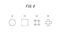
- Preferably, the calibration marker is formed of two lines orthogonal to each other and an intersection of the two lines indicates the display position of the calibration marker. Thereby, a size of the calibration marker is increased, allowing the operator to easily recognize the calibration marker in the display panel such as a display and improving operability.
- The calibration marker may be in a shape surrounding a predetermined area, and the calculation unit may calculate the camera mounting angle based on the display position of the calibration marker when the calibration marker is displayed overlapping the two points of the calibration mark.
- Preferably, the calibration mark is formed of a line connecting the two separate points.
- The image superimposing unit may highlight the calibration marker being shifted.
- The image taken by the camera is output, after the calculation unit calculates parameters, being offset by an amount corresponding to the parameters.
- Alternatively, the image taken by the camera is output, after the calculation unit calculates the parameters, being offset by the amount corresponding to the parameters, or the image superimposing unit, when superimposing a predetermined image on the image taken by the camera, sets an offset for a superimposing position by the amount corresponding to the parameters.
- The camera calibration device may further include a display for displaying an image in which the calibration marker is superimposed on the image including the calibration mark. Further, the camera calibration device may be constituted, without the imaging unit, by using: an image superimposing unit configured to process an image signal such that the calibration marker is superimposed on the image including the calibration mark having two separate points on a plane; an instruction unit configured to instruct on a display position of the calibration marker superimposed on the image; and a calculation unit configured to calculate the camera mounting angle based on the display position of the calibration marker when the calibration marker is superimposed on the image overlapping the two points of the calibration mark.
- In order to solve the above problem, a camera calibration method according to one embodiment for calibrating a camera mounting angle on a vehicle by calculating the mounting angle by taking an image of a calibration mark, includes: a step to take an image including the calibration mark having two separate points on a plane; a step to superimpose a calibration marker on the image; a step to instruct on a display position of the calibration marker superimposed on the image; and a step to calculate the camera mounting angle based on the display position of the calibration marker superimposed overlapping the two points of the calibration mark.
- The camera calibration method according to the embodiments may be appropriately substantialized by the calibration device described above (included in each embodiment).
- Also, a camera according to one embodiment, capable of calibrating a camera mounting angle on a vehicle by calculating the camera mounting angle by taking an image of a calibration mark, includes: an imaging unit configured to take an image including the calibration mark having two separate points on a plane; an image superimposing unit configured to process an image signal such that a calibration marker is superimposed on the image; an instruction reception unit configured to receive an instruction on a display position of the calibration marker superimposed on the image; and a calculation unit configured to calculate the camera mounting angle based on the display position of the calibration marker superimposed overlapping the two points of the calibration mark.
- The camera according to the embodiments may be appropriately substantialized by having the calibration device (included in each embodiment) described above.
-
-
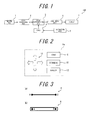
FIG. 1 is a block diagram illustrating an entire configuration of a camera calibration device according to one embodiment of the present invention. -
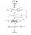
FIG. 2 is a diagram illustrating examples of operation units of an instruction unit serving as a user interface. -
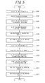
FIGS. 3 (a) and (b) are diagrams illustrating variations of a form of a calibration mark imaged by an imaging unit in calibration. -
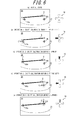
FIG. 4 is a flowchart illustrating control by a CPU in steps. -
FIG 5 is a flowchart illustrating a shift operation of a calibration marker according to the present invention. -
FIGS. 6(a)-(e) are diagrams illustrating an example of a shift of the calibration marker by the camera calibration device according to one embodiment of the present invention. -
FIG. 7 is a diagram illustrating a positional relationship between the imaging unit provided to a vehicle and the calibration mark. -
FIGS. 8(a)-(c) are diagrams illustrating examples of rotation in a world coordinate system. -
FIGS. 9(a)-(b) are diagrams illustrating examples of the calibration marker. -
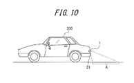
FIG 10 is a diagram illustrating a vehicle having a camera mounted thereon. -
FIG. 1 is a block diagram illustrating an entire configuration of acamera calibration device 100 according to one embodiment. Animaging unit 1 serving as a camera (an onboard camera) mounted on a vehicle (for example, a car) has an image sensor such as CMOS or CCD for converting the light of a subject entering through a lens (not illustrated) into an electric signal.FIG. 10 is a diagram illustrating the vehicle having theimaging unit 1 mounted thereon. According to the present embodiment, as illustrated inFIG. 10 , theimaging unit 1 is mounted near arear bumper 21 of avehicle 200 to take an image behind thevehicle 200. An area A in the figure represents an area captured by theimaging unit 1. - A display 7, when a user selects a parking mode, displays an image generated by the
camera calibration device 100. The parking mode assists smooth parking by displaying, on the display 7, an image in the area A behind thevehicle 200 where it is difficult for the user driving thevehicle 200 to view. A predicted track of thevehicle 200 may be superimposed on the image in the area A behind thevehicle 200, for assisting smoother parking. - Also, when the user selects a camera calibration mode, the image generated by the
camera calibration device 100 is displayed. The camera calibration mode, by disposing a subject or figure serving as mark in the area A behind thevehicle 200, allows the user to calibrate a mounting position of theimaging unit 1 by using an image of the mark taken by theimaging unit 1. The camera calibration mode is used when theimaging unit 1 is mounted on thevehicle 200 in a production line of thevehicle 200 or when the imaging unit 1is displaced due to vibrations of thevehicle 200 or the like. A calibration method will be described in detail below. - When a navigation mode is selected by the user, the display 7 may display a route map to a destination obtained by a navigation system. When a TV mode is selected, the display 7 may display television obtained by a TV receiver.
- An
image processing unit 2, by processing the electric signal output from theimaging unit 1, generates an image signal for displaying a digital image in, for example, a progressive form or an interlace form. - An
image superimposing unit 3, such that a calibration marker used in calibration described below or the predicted track followed by the vehicle moving backward is superimposed as graphic data at a predetermined position on the image taken by theimaging unit 1, processes the image signal input from theimage processing unit 2. - Display of the calibration marker superimposed on the image is controlled according to an instruction by a CPU (calculation unit) 4. Especially, a display position of the calibration marker is controlled by the
CPU 4 via an instruction unit 5 serving as a user interface that may be operated by an operator. The instruction unit 5 has anoperation unit 5 a that allows an input of an instruction to shift the display position of the calibration marker on the image. - Note that a configuration of the camera of the camera calibration device is not particularly limited and may include, for example, the
imaging unit 1, theimage processing unit 2, theimage superimposing unit 3, theCPU 4 and animage output unit 6. -
FIG. 2 illustrates an example of theoperation unit 5a of the instruction unit 5 serving as the user interface. Theoperation unit 5a includes astart button 9 operated at the start of calibration, ashift button 10 for moving the calibration marker in vertical and horizontal directions, aposition determination button 11 operated at the end of shift of the calibration marker, and anexecution button 12 operated for executing calibration. However, theoperation unit 5a is not limited to the example illustrated inFIG. 2 but may be, for example, a mouse, a keyboard, a joystick or a touch panel. Also, the buttons set forth above may be mechanical switches or objects displayed on the touch panel laminated on the display 7. - Referring back to
FIG. 1 , the image having the calibration marker superimposed thereon by theimage superimposing unit 3 is converted by theimage output unit 6 into the image signal in a format (for example, NTSC or the like) appropriate for display. Then, when the converted image signal is input to the display 7 serving as a display means, the image is displayed on a screen. - A
calibration mark 8 is the subject or figure disposed at a predetermined distance (for example, 1 m) from a rear edge of thevehicle 200 when thevehicle 100 is accurately stopped at a predetermined parking position, and takes the shape of, for example, a rectangular plate or a white line drawn on a road. That is, when the camera is mounted at a correct angle, a positional relationship between thevehicle 200 and thecalibration mark 8 is specified, thus thecalibration mark 8 taken by the imaging unit1 is always displayed at a particular position in the image displayed on the display 7. When thecalibration mark 8 is displayed off the particular position, calibration parameters for specifying deviation of a mounting angle of the imaging unit1 may be obtained by shifting the calibration marker to thecalibration mark 8 by using the instruction unit 5. -
FIG 3 is a diagram illustrating variations of a form of thecalibration mark 8 imaged by theimaging unit 1 in calibration. Thecalibration mark 8 according to the present embodiment has two points A and B having a predetermined distance therebetween on a plane. - In an example in
FIG. 3 (a) , thecalibration mark 8 is formed of a line connecting the two points A and B on the plane. Since thecalibration object 8 has the points A and B at the ends of the line, the operator may easily recognize thecalibration mark 8 displayed in the display 7. Although both ends of themark 8 have a black dot denoting the point A or B inFIG. 3(a) , these dots are not necessary and the line may be thicker for easy recognition by the operator. As illustrated inFIG. 3(b) , also, thecalibration mark 8 may be in the form of a frame including the points A and B at both edges thereof. - Although the
calibration mark 8 according to the present embodiment may take a variety of forms, thecalibration mark 8 having the form illustrated inFIG. 3(a) (the line without the dots at both ends thereof) is used as an example in the description below. - Now, control by the
CPU 4 will be described in detail referring toFIG. 4. FIG. 4 is a flowchart illustrating the control by theCPU 4 in steps. - First, the
CPU 4 determines whether the instruction unit 5 is requested to change the display position of the calibration marker for calibration (step S101), by detecting an operation of thestart button 9 of theoperation unit 5a of the instruction unit 5 by the operator. - When the operation of the
start button 9 is detected, theCPU 4 then detects which one of theshift button 10 corresponding to shift in the vertical direction or in the horizontal direction is operated by the operator (step S101) and, based on the direction of the shift button operated, shifts the display position of the calibration marker (step S102). Such operation to shift the calibration marker is performed in real time by the operator viewing the display position of the calibration marker in the panel of the display 7. When there is no request at step S101 (No at step S101), theCPU 4 proceeds to step S103 described below skipping the process at step S102. -
FIG. 5 is a flowchart illustrating an operation to shift the calibration marker at step S102.FIG. 6 is a diagram illustrating an example of a shift of the calibration marker by thecamera calibration device 100 according to the present embodiment. Referring toFIGS. 5 and6 , the calibration using the calibration marker will be described. Preferably, theimage superimposing unit 3, in order to improve operability of the user by clearly indicatingcalibration markers FIGS. 5 and6 , the calibration marker is highlighted. -
FIG. 6(a) illustrates an initial state where the image (including arear bumper 21 of the vehicle having thecamera calibration device 100 mounted thereon and thecalibration mark 8 provided on the road behind the vehicle) taken by theimaging unit 1, and thecalibration markers display panel 20. - The
calibration markers calibration mark 8 displayed in the display 7 and the display positions of thecalibration markers shift button 10 of the instruction unit 5. Since the display positions of thecalibration markers calibration markers calibration mark 8. - When a single pressing of the
shift button 10 is made correspond to offset at 0.5 degree, thecalibration markers shift button 10 for shifting the calibration markers in the horizontal direction, are shifted by the number of pixels equivalent to a shift amount of the image when an image taking direction of the camera is directed by 0.5 degree in a pan (horizontal) direction. The same applies to a tilt (vertical) direction. - First, the operator selects the
calibration marker 14a, between thecalibration markers calibration marker 14a is selected at step S201, theimage superimposing unit 3 highlights thecalibration marker 14a to be shifted, for easy distinguishing from thecalibration marker 14b not to be shifted (step S202).FIGS. 6(b) and (c) illustrate a state that thecalibration marker 14a is blinking (highlighted). - The operator, by operating the
shift button 10 corresponding to a left direction, shifts thecalibration marker 14a in the left direction as illustrated inFIG. 6(b) such that thecalibration marker 14a meets a coordinate of the left end A of thecalibration object 8 in the horizontal direction (step S203). Subsequently, the operator, by operating theshift button 10 corresponding to an upward direction, shifts thecalibration marker 14a upward as illustrated inFIG. 6(c) such that the thecalibration marker 14a meets a coordinate of the left end A in the vertical direction (step S204). When the coordinates of the left end A of thecalibration mark 8 meet coordinates of thecalibration marker 14a, the operator instructs to end positioning of thecalibration marker 14a (step S205). The operator may instruct to end positioning by, for example, holding theshift button 10 down or pressing theshift button 10 twice (double click). Alternatively, an instruction end button is provided to theoperation unit 5a for allowing the operator to operate to end positioning. Upon receiving the instruction to end positioning from the instruction unit 5, theCPU 4 controls theimage superimposing unit 3 to end highlighting (step S206). - Next, the operator selects the
calibration marker 14b, between the two calibration markers, displayed on the right side in the display panel (step S207). Alternatively, theCPU 4 may automatically select thecalibration marker 14b upon receiving the instruction to end positioning of thecalibration marker 14a from the instruction unit 5. When thecalibration marker 14b is selected at step S207, theimage superimposing unit 3 highlights thecalibration marker 14b to be shifted, for distinguishing from thecalibration marker 14a not to be shifted (step S208).FIGS. 6(d) and (e) illustrate a state that thecalibration marker 14b is blinking (highlighted). - The operator, in a similar manner for shifting the
calibration marker 14a described above, operates theshift button 10 corresponding to the left direction as illustrated inFIG. 6(d) such that thecalibration marker 14b meets a coordinate of the right end B of the calibration mark in the horizontal direction(step S209). Subsequently, the operator, by operating theshift button 10 corresponding to the upward direction, shifts thecalibration marker 14b upward as illustrated inFIG. 6(e) such that thecalibration marker 14b meets a coordinate of the right end B of the calibration mark in the vertical direction (step S210). When the coordinates of the right end B of thecalibration mark 8 meets coordinates of thecalibration marker 14b, the operator instructs to end positioning of thecalibration marker 14b (step S211). The operator may instruct to end positioning by, for example, holding theshift button 10 down or pressing theshift button 10 twice (double click). Alternatively, the instruction end button is provided to theoperation unit 5a for allowing the operator to operate to end positioning. Upon receiving the instruction to end positioning from the instruction unit 5, theCPU 4 controls theimage superimposing unit 3 to end highlighting (step S212). - As described above, the
camera calibration device 100 according to the present embodiment may adjust thecalibration markers calibration mark 8 simply by shifting thecalibration markers shift button 10 of the operation unit 5 of the instruction unit 5 may be simplified as a rotating operation is not necessary, which is excellent in terms of cost reduction. - Referring back to
FIG. 4 , theCPU 4 determines whether shift of the display positions of thecalibration markers position determination button 11 of theoperation unit 5a is operated by the operator. When the operator operates theexecution button 12, calibration parameters (a roll angle, a pan angle and a tilt angle of the camera) are calculated based on the determined display positions of thecalibration markers calibration markers - Next, a method for calculating the calibration parameters at step S104 will be described.
FIG. 7 is a diagram illustrating a positional relationship between the imaging unit 1 (camera) provided to the vehicle and thecalibration mark 8. Theimaging unit 1 is provided at the rear part of the vehicle, and the mounting position of theimaging unit 1 is represented by a point (tx, ty, tz) in a world coordinate system (Xw, Yw, Zw) as an absolute coordinate. Although acenter 0 of an edge of the rear bumper of the vehicle is set to be an origin of the world coordinate system (Xw, Yw, Zw) in an example inFIG. 7 , it is needless to say that any point in the space may be set as the origin, provided that positions in the entire system may be defined unambiguously. - In the system having the position of the
imaging unit 1 as the origin, a relative positional relationship may be represented by a camera coordinate system (Xc, Yc, Zc). The camera coordinate system (Xc, Yc, Zc) is represented as a relative coordinate system (a literal shift and a rotational shift in the world coordinate system) having the world coordinate (tx, ty, tz) of theimaging unit 1 as the origin.FIG. 8 is a diagram illustrating examples of a rotation in the world coordinate system (Xw, Yw, Zw), andFIGS. 8(a), (b) and (c) illustrate a rotation (pan) about an axis Zw, a rotation (roll) about an axis Yw and a rotation (tilt) about an axis Xw, respectively. When α, β and γ represent a rotation angle of the pan, a rotation angle of the roll and a rotation angle of the tilt, respectively, a relationship between the camera coordinate system (Xc, Yc, Zc) and the world coordinate system (Xw, Yw, Zw) may be represented by the following Formula (1).
[Formula 1]
- Here, a relationship between an incident angle θi of the light of a subject on the lens of the
imaging unit 1 and an image height y on the image sensor of theimaging unit 1 is defined by the following Formula (2) when, for example, a pinhole lens is employed. In Formula (2), f represents a focal length of the lens.
[Formula 2]
- The incident angle θi on the lens may be calculated from the following Formula (3).
[Formula 3]
- Based on the image height y, on the other hand, an image coordinate system (xi, yi) is defined by the following Formulas (4), (5) and (6). Here, Xmax and Ymax represent an image size in the vertical direction and in the horizontal direction, respectively, and pix_x and pix_y represent a pixel size of the sensor in the vertical direction and in the horizontal direction, respectively. Since coordinates of the calibration points in the world coordinate system are known, when coordinates of two calibration points A and B on the image is determined by a sequential operation of the instruction unit 5 illustrated in
FIG. 6 , each of the pan angle, the roll angle and the tilt angle may be calculated from Formulas (1)-(6).
[Formula 4]


- After the
CPU 4 calculates the calibration parameters, theimaging unit 1 outputs the image offset by an amount corresponding to the calibration parameters, or theimage superimposing unit 3 sets offset for the superimposed image from theimaging unit 1 by the amount corresponding to the calibration parameters. As a result, theimage superimposing unit 3, in generating the superimposed image by superimposing an image such as the predicted track or the like on the digital image generated by theimage processing unit 2, superimposes the predicted track or the like offset from its superimposing position prior to calculation of the calibration parameters. Therefore, a highly accurate predicted vehicle track may be displayed in parking, for example. - The camera calibration device according to the present embodiment, as described above, without an complex operation such as repetitive fine adjustments, enables to easily adjust the display positions of the
calibration markers calibration mark 8 and to calculate the mounting angle (the pan angle, roll angle and tilt angle) of the imaging unit 1 (camera) for calibration. Especially, since the display positions of thecalibration markers - Note that it takes some time to finely adjust the positions of the
calibration markers calibration mark 8, and also that, when thecalibration markers calibration mark 8, obtainment of the calibration parameters is not affected. Therefore, it is preferable that thecalibration markers CPU 4 obtains the coordinate of the positions of thecalibration markers calibration markers calibration mark 8.FIG. 9 is a diagram illustrating examples of the calibration marker. Each of the calibration markers illustrated inFIGS. 9(a)-(d) are shaped to surround the predetermined area. - The present invention is applicable to the camera calibration device, for calibration of a camera mounting angle on the vehicle by calculating the camera mounting angle by taking an image of the calibration mark, the camera and the camera calibration method.
-
- 1
- Imaging Unit
- 2
- Image Processing Unit
- 3
- Image Superimposing Unit
- 4
- CPU (Calculation Unit)
- 5
- Instruction Unit
- 5a
- Operation unit
- 6
- Image Output unit
- 7
- Display
- 8
- Calibration Mark
- 9
- Start Button
- 10
- Shift Button
- 11
- Position Determination Button
- 12
- Execution Button
- 14
- Calibration Marker
- 20
- Display Panel
- 21
- Rear Bumper
- 100
- Camera Calibration Device
- 200
- Vehicle
Claims (13)
- A camera calibration device for calibrating a camera mounting angle on a vehicle by calculating the camera mounting angle by taking an image of a calibration mark, comprising:an imaging unit configured to take the image including the calibration mark having two separate points on a plane;an image superimposing unit configured to process an image signal such that a calibration marker is superimposed on the image;an instruction unit configured to instruct on a position to superimpose the calibration marker in the image; anda calculation unit configured to calculate parameters for calibrating deviation of the camera mounting angle based on a display position of the calibration marker when the calibration marker is superimposed overlapping the two points of the calibration mark.
- The camera calibration device according to claim 1, wherein the calibration marker is shifted in vertical and horizontal directions.
- The camera calibration device according to claim 1, wherein two calibration markers are displayed on the image so as to correspond to two separate points of the calibration mark and display positions of the calibration markers may be separately controlled by an instruction means.
- The camera calibration device according to claim 1, wherein the calibration marker is formed of two lines orthogonal to each other and an intersection of the two lines indicates the display position of the calibration marker.
- The camera calibration device according to claim 1, wherein the calibration marker is in a shape surrounding a predetermined area, and
the calculation unit calculates the camera mounting angle based on the display position of the calibration marker when the calibration marker is displayed overlapping the two points of the calibration mark. - The camera calibration device according to claim 1, wherein the calibration mark is formed of a line connecting the two separate points.
- The camera calibration device according to claim 1, wherein the image superimposing unit highlights the calibration marker being shifted.
- The camera calibration device according to claim 1, wherein the image taken by the camera is output, after the calculation unit calculates the parameters, being offset by an amount corresponding to the parameters.
- The camera calibration device according to claim 1, wherein the image superimposing unit, when superimposing a predetermined image on the image taken by the camera, sets an offset for a superimposing position by the amount corresponding to the parameters.
- The camera calibration device according to claim 1, further comprising a display for displaying an image in which the calibration marker is superimposed on the image including the calibration mark.
- A camera calibration device for calibrating a camera mounting angle on a vehicle by calculating the camera mounting angle by taking an image of a calibration mark, comprising:an image superimposing unit configured to process an image signal such that a calibration marker is superimposed on the image including the calibration mark having two separate points on a plane;an instruction unit configured to instruct on a display position of the calibration marker superimposed on the image; anda calculation unit configured to calculate the camera mounting angle based on the display position of the calibration marker when the calibration marker is superimposed overlapping the two points of the calibration mark.
- A camera calibration method for calibrating a camera mounting angle on a vehicle by calculating the mounting angle by taking an image of a calibration mark, comprising:a step to take an image including the calibration mark having two separate points on a plane;a step to superimpose a calibration marker on the image;a step to instruct on a display position of the calibration marker superimposed on the image; anda step to calculate the camera mounting angle based on the display position of the calibration marker superimposed overlapping the two points of the calibration mark.
- A camera capable of calibrating a camera mounting angle on a vehicle by calculating the camera mounting angle by taking an image of a calibration mark, comprising:an imaging unit configured to take an image including the calibration mark having two separate points on a plane;an image superimposing unit configured to process an image signal such that a calibration marker is superimposed on the image;an instruction reception unit configured to receive an instruction on a display position of the calibration marker superimposed on the image; anda calculation unit configured to calculate the camera mounting angle based on the display position of the calibration marker superimposed overlapping the two points of the calibration mark.
Applications Claiming Priority (3)
| Application Number | Priority Date | Filing Date | Title |
|---|---|---|---|
| JP2011200005A JP2013062692A (en) | 2011-09-13 | 2011-09-13 | Calibration device and method for on-vehicle camera |
| JP2012039417A JP2013173453A (en) | 2012-02-24 | 2012-02-24 | Calibration processing device, camera calibrating device, camera system and camera calibrating method |
| PCT/JP2012/005853 WO2013038681A1 (en) | 2011-09-13 | 2012-09-13 | Camera calibration device, camera, and camera calibration method |
Publications (2)
| Publication Number | Publication Date |
|---|---|
| EP2757768A1 true EP2757768A1 (en) | 2014-07-23 |
| EP2757768A4 EP2757768A4 (en) | 2016-07-13 |
Family
ID=47882930
Family Applications (1)
| Application Number | Title | Priority Date | Filing Date |
|---|---|---|---|
| EP12832652.7A Withdrawn EP2757768A4 (en) | 2011-09-13 | 2012-09-13 | Camera calibration device, camera, and camera calibration method |
Country Status (4)
| Country | Link |
|---|---|
| US (1) | US20130215280A1 (en) |
| EP (1) | EP2757768A4 (en) |
| CN (1) | CN103797779A (en) |
| WO (1) | WO2013038681A1 (en) |
Cited By (2)
| Publication number | Priority date | Publication date | Assignee | Title |
|---|---|---|---|---|
| US10769813B2 (en) | 2018-08-28 | 2020-09-08 | Bendix Commercial Vehicle Systems, Llc | Apparatus and method for calibrating surround-view camera systems |
| US11385105B2 (en) | 2016-04-04 | 2022-07-12 | Teledyne Flir, Llc | Techniques for determining emitted radiation intensity |
Families Citing this family (7)
| Publication number | Priority date | Publication date | Assignee | Title |
|---|---|---|---|---|
| JP6012982B2 (en) * | 2012-02-24 | 2016-10-25 | 京セラ株式会社 | Calibration processing apparatus, camera calibration apparatus, camera system, and camera calibration method |
| JP6260424B2 (en) * | 2014-04-16 | 2018-01-17 | 株式会社デンソー | In-vehicle camera mounting error detection device |
| CN105744254B (en) * | 2014-12-30 | 2017-12-29 | 钰立微电子股份有限公司 | Correct guidance system and correct the operating method of guidance system |
| KR102543523B1 (en) * | 2016-09-09 | 2023-06-15 | 현대모비스 주식회사 | System and method for correcting error of camera |
| JP7037413B2 (en) * | 2018-03-28 | 2022-03-16 | 京セラ株式会社 | Imaging device, moving object, and imaging method |
| CN112637585A (en) * | 2020-12-15 | 2021-04-09 | 上海交通建设总承包有限公司 | Correction method for perspective dislocation phenomenon in panoramic shooting process of single lens reflex camera |
| JP2023106132A (en) * | 2022-01-20 | 2023-08-01 | キヤノン株式会社 | Information processing apparatus and information processing method, imaging apparatus, program, and storage medium |
Family Cites Families (6)
| Publication number | Priority date | Publication date | Assignee | Title |
|---|---|---|---|---|
| US6813371B2 (en) * | 1999-12-24 | 2004-11-02 | Aisin Seiki Kabushiki Kaisha | On-vehicle camera calibration device |
| JP3551920B2 (en) | 1999-12-24 | 2004-08-11 | アイシン精機株式会社 | In-vehicle camera calibration device and calibration method |
| JP2004200819A (en) * | 2002-12-17 | 2004-07-15 | Clarion Co Ltd | Method of calibrating mounted camera and calibrator |
| JP4681856B2 (en) * | 2004-11-24 | 2011-05-11 | アイシン精機株式会社 | Camera calibration method and camera calibration apparatus |
| JP5091902B2 (en) * | 2009-03-31 | 2012-12-05 | アイシン精機株式会社 | Calibration index used for calibration of in-vehicle camera, in-vehicle camera calibration method and system using the calibration index, and program for the system |
| JP4690476B2 (en) * | 2009-03-31 | 2011-06-01 | アイシン精機株式会社 | Car camera calibration system |
-
2012
- 2012-08-01 US US13/564,612 patent/US20130215280A1/en not_active Abandoned
- 2012-09-13 WO PCT/JP2012/005853 patent/WO2013038681A1/en active Application Filing
- 2012-09-13 CN CN201280044643.5A patent/CN103797779A/en active Pending
- 2012-09-13 EP EP12832652.7A patent/EP2757768A4/en not_active Withdrawn
Cited By (2)
| Publication number | Priority date | Publication date | Assignee | Title |
|---|---|---|---|---|
| US11385105B2 (en) | 2016-04-04 | 2022-07-12 | Teledyne Flir, Llc | Techniques for determining emitted radiation intensity |
| US10769813B2 (en) | 2018-08-28 | 2020-09-08 | Bendix Commercial Vehicle Systems, Llc | Apparatus and method for calibrating surround-view camera systems |
Also Published As
| Publication number | Publication date |
|---|---|
| US20130215280A1 (en) | 2013-08-22 |
| EP2757768A4 (en) | 2016-07-13 |
| WO2013038681A1 (en) | 2013-03-21 |
| CN103797779A (en) | 2014-05-14 |
Similar Documents
| Publication | Publication Date | Title |
|---|---|---|
| EP2818363B1 (en) | Camera device, camera system, and camera calibration method | |
| EP2757768A1 (en) | Camera calibration device, camera, and camera calibration method | |
| EP2835962B1 (en) | Calibration processor, camera device, camera system, and camera calibration method | |
| US8953043B2 (en) | Parking assistance device configured to generate forward guide markers | |
| JP5729158B2 (en) | Parking assistance device and parking assistance method | |
| JP5316805B2 (en) | In-vehicle camera device image adjustment device and in-vehicle camera device | |
| JP5003946B2 (en) | Parking assistance device | |
| US20160176349A1 (en) | Vehicle peripheral observation device | |
| JP4832321B2 (en) | Camera posture estimation apparatus, vehicle, and camera posture estimation method | |
| JP4758481B2 (en) | VEHICLE IMAGE PROCESSING DEVICE AND VEHICLE IMAGE PROCESSING PROGRAM | |
| JP5724446B2 (en) | Vehicle driving support device | |
| JP2001218197A (en) | Device for displaying periphery of vehicle | |
| JP2010167893A (en) | Vehicle periphery display device | |
| JP2013154730A (en) | Apparatus and method for processing image, and parking support system | |
| US20100020176A1 (en) | Image processing system, imaging device, image processing method, and computer program | |
| JP2007168560A (en) | Parking support apparatus | |
| JP2008037118A (en) | Display for vehicle | |
| JP2013062692A (en) | Calibration device and method for on-vehicle camera | |
| JP4059309B2 (en) | In-vehicle camera image display control method and apparatus | |
| JP5143596B2 (en) | Image display device for vehicle | |
| JP2014193661A (en) | Parking support device | |
| JP2013173453A (en) | Calibration processing device, camera calibrating device, camera system and camera calibrating method | |
| JP2007028444A (en) | Image display system | |
| JP2005035542A (en) | Parking assisting device |
Legal Events
| Date | Code | Title | Description |
|---|---|---|---|
| PUAI | Public reference made under article 153(3) epc to a published international application that has entered the european phase |
Free format text: ORIGINAL CODE: 0009012 |
|
| 17P | Request for examination filed |
Effective date: 20140313 |
|
| AK | Designated contracting states |
Kind code of ref document: A1 Designated state(s): AL AT BE BG CH CY CZ DE DK EE ES FI FR GB GR HR HU IE IS IT LI LT LU LV MC MK MT NL NO PL PT RO RS SE SI SK SM TR |
|
| DAX | Request for extension of the european patent (deleted) | ||
| RA4 | Supplementary search report drawn up and despatched (corrected) |
Effective date: 20160609 |
|
| RIC1 | Information provided on ipc code assigned before grant |
Ipc: B60R 1/00 20060101ALI20160603BHEP Ipc: H04N 7/18 20060101ALI20160603BHEP Ipc: B60R 11/04 20060101ALI20160603BHEP Ipc: H04N 5/225 20060101AFI20160603BHEP Ipc: H04N 17/00 20060101ALI20160603BHEP |
|
| STAA | Information on the status of an ep patent application or granted ep patent |
Free format text: STATUS: THE APPLICATION IS DEEMED TO BE WITHDRAWN |
|
| 18D | Application deemed to be withdrawn |
Effective date: 20170110 |