EP1268248B1 - Kolbenpumpe - Google Patents
Kolbenpumpe Download PDFInfo
- Publication number
- EP1268248B1 EP1268248B1 EP01936090A EP01936090A EP1268248B1 EP 1268248 B1 EP1268248 B1 EP 1268248B1 EP 01936090 A EP01936090 A EP 01936090A EP 01936090 A EP01936090 A EP 01936090A EP 1268248 B1 EP1268248 B1 EP 1268248B1
- Authority
- EP
- European Patent Office
- Prior art keywords
- piston
- spring
- valve
- pump
- valve seat
- Prior art date
- Legal status (The legal status is an assumption and is not a legal conclusion. Google has not performed a legal analysis and makes no representation as to the accuracy of the status listed.)
- Expired - Lifetime
Links
- 238000013016 damping Methods 0.000 claims description 15
- 230000000717 retained effect Effects 0.000 claims 1
- 229910052782 aluminium Inorganic materials 0.000 description 5
- XAGFODPZIPBFFR-UHFFFAOYSA-N aluminium Chemical compound [Al] XAGFODPZIPBFFR-UHFFFAOYSA-N 0.000 description 5
- 125000006850 spacer group Chemical group 0.000 description 5
- 238000010276 construction Methods 0.000 description 4
- 238000004519 manufacturing process Methods 0.000 description 4
- 229910000831 Steel Inorganic materials 0.000 description 3
- 239000011324 bead Substances 0.000 description 3
- 239000012530 fluid Substances 0.000 description 3
- 238000007789 sealing Methods 0.000 description 3
- 239000010959 steel Substances 0.000 description 3
- 230000000712 assembly Effects 0.000 description 2
- 238000000429 assembly Methods 0.000 description 2
- 238000013461 design Methods 0.000 description 2
- 238000011161 development Methods 0.000 description 2
- 239000007787 solid Substances 0.000 description 2
- 238000012549 training Methods 0.000 description 2
- 238000005299 abrasion Methods 0.000 description 1
- 238000013459 approach Methods 0.000 description 1
- 238000002788 crimping Methods 0.000 description 1
- 230000000694 effects Effects 0.000 description 1
- 238000007667 floating Methods 0.000 description 1
- 238000005304 joining Methods 0.000 description 1
- 239000000463 material Substances 0.000 description 1
- 229910052751 metal Inorganic materials 0.000 description 1
- 239000002184 metal Substances 0.000 description 1
- 239000000203 mixture Substances 0.000 description 1
- 238000012856 packing Methods 0.000 description 1
- 239000002245 particle Substances 0.000 description 1
- 239000004033 plastic Substances 0.000 description 1
- 230000036316 preload Effects 0.000 description 1
- 238000003825 pressing Methods 0.000 description 1
- 238000005096 rolling process Methods 0.000 description 1
- 238000007493 shaping process Methods 0.000 description 1
Images



Classifications
-
- B—PERFORMING OPERATIONS; TRANSPORTING
- B60—VEHICLES IN GENERAL
- B60T—VEHICLE BRAKE CONTROL SYSTEMS OR PARTS THEREOF; BRAKE CONTROL SYSTEMS OR PARTS THEREOF, IN GENERAL; ARRANGEMENT OF BRAKING ELEMENTS ON VEHICLES IN GENERAL; PORTABLE DEVICES FOR PREVENTING UNWANTED MOVEMENT OF VEHICLES; VEHICLE MODIFICATIONS TO FACILITATE COOLING OF BRAKES
- B60T8/00—Arrangements for adjusting wheel-braking force to meet varying vehicular or ground-surface conditions, e.g. limiting or varying distribution of braking force
- B60T8/32—Arrangements for adjusting wheel-braking force to meet varying vehicular or ground-surface conditions, e.g. limiting or varying distribution of braking force responsive to a speed condition, e.g. acceleration or deceleration
- B60T8/34—Arrangements for adjusting wheel-braking force to meet varying vehicular or ground-surface conditions, e.g. limiting or varying distribution of braking force responsive to a speed condition, e.g. acceleration or deceleration having a fluid pressure regulator responsive to a speed condition
- B60T8/40—Arrangements for adjusting wheel-braking force to meet varying vehicular or ground-surface conditions, e.g. limiting or varying distribution of braking force responsive to a speed condition, e.g. acceleration or deceleration having a fluid pressure regulator responsive to a speed condition comprising an additional fluid circuit including fluid pressurising means for modifying the pressure of the braking fluid, e.g. including wheel driven pumps for detecting a speed condition, or pumps which are controlled by means independent of the braking system
-
- F—MECHANICAL ENGINEERING; LIGHTING; HEATING; WEAPONS; BLASTING
- F04—POSITIVE - DISPLACEMENT MACHINES FOR LIQUIDS; PUMPS FOR LIQUIDS OR ELASTIC FLUIDS
- F04B—POSITIVE-DISPLACEMENT MACHINES FOR LIQUIDS; PUMPS
- F04B53/00—Component parts, details or accessories not provided for in, or of interest apart from, groups F04B1/00 - F04B23/00 or F04B39/00 - F04B47/00
- F04B53/10—Valves; Arrangement of valves
- F04B53/1002—Ball valves
-
- B—PERFORMING OPERATIONS; TRANSPORTING
- B60—VEHICLES IN GENERAL
- B60T—VEHICLE BRAKE CONTROL SYSTEMS OR PARTS THEREOF; BRAKE CONTROL SYSTEMS OR PARTS THEREOF, IN GENERAL; ARRANGEMENT OF BRAKING ELEMENTS ON VEHICLES IN GENERAL; PORTABLE DEVICES FOR PREVENTING UNWANTED MOVEMENT OF VEHICLES; VEHICLE MODIFICATIONS TO FACILITATE COOLING OF BRAKES
- B60T8/00—Arrangements for adjusting wheel-braking force to meet varying vehicular or ground-surface conditions, e.g. limiting or varying distribution of braking force
- B60T8/32—Arrangements for adjusting wheel-braking force to meet varying vehicular or ground-surface conditions, e.g. limiting or varying distribution of braking force responsive to a speed condition, e.g. acceleration or deceleration
- B60T8/34—Arrangements for adjusting wheel-braking force to meet varying vehicular or ground-surface conditions, e.g. limiting or varying distribution of braking force responsive to a speed condition, e.g. acceleration or deceleration having a fluid pressure regulator responsive to a speed condition
- B60T8/40—Arrangements for adjusting wheel-braking force to meet varying vehicular or ground-surface conditions, e.g. limiting or varying distribution of braking force responsive to a speed condition, e.g. acceleration or deceleration having a fluid pressure regulator responsive to a speed condition comprising an additional fluid circuit including fluid pressurising means for modifying the pressure of the braking fluid, e.g. including wheel driven pumps for detecting a speed condition, or pumps which are controlled by means independent of the braking system
- B60T8/4031—Pump units characterised by their construction or mounting
-
- F—MECHANICAL ENGINEERING; LIGHTING; HEATING; WEAPONS; BLASTING
- F04—POSITIVE - DISPLACEMENT MACHINES FOR LIQUIDS; PUMPS FOR LIQUIDS OR ELASTIC FLUIDS
- F04B—POSITIVE-DISPLACEMENT MACHINES FOR LIQUIDS; PUMPS
- F04B1/00—Multi-cylinder machines or pumps characterised by number or arrangement of cylinders
- F04B1/04—Multi-cylinder machines or pumps characterised by number or arrangement of cylinders having cylinders in star- or fan-arrangement
- F04B1/0404—Details or component parts
- F04B1/0426—Arrangements for pressing the pistons against the actuated cam; Arrangements for connecting the pistons to the actuated cam
-
- F—MECHANICAL ENGINEERING; LIGHTING; HEATING; WEAPONS; BLASTING
- F04—POSITIVE - DISPLACEMENT MACHINES FOR LIQUIDS; PUMPS FOR LIQUIDS OR ELASTIC FLUIDS
- F04B—POSITIVE-DISPLACEMENT MACHINES FOR LIQUIDS; PUMPS
- F04B53/00—Component parts, details or accessories not provided for in, or of interest apart from, groups F04B1/00 - F04B23/00 or F04B39/00 - F04B47/00
- F04B53/10—Valves; Arrangement of valves
-
- Y—GENERAL TAGGING OF NEW TECHNOLOGICAL DEVELOPMENTS; GENERAL TAGGING OF CROSS-SECTIONAL TECHNOLOGIES SPANNING OVER SEVERAL SECTIONS OF THE IPC; TECHNICAL SUBJECTS COVERED BY FORMER USPC CROSS-REFERENCE ART COLLECTIONS [XRACs] AND DIGESTS
- Y10—TECHNICAL SUBJECTS COVERED BY FORMER USPC
- Y10T—TECHNICAL SUBJECTS COVERED BY FORMER US CLASSIFICATION
- Y10T137/00—Fluid handling
- Y10T137/7504—Removable valve head and seat unit
- Y10T137/7559—Pump type
Definitions
- the invention relates to a piston pump according to the preamble of claim 1.
- Such pumps are particularly in controllable braking systems like ABS or ESP widely used. Due to the mass production be at their cost-effective production and Assembly therefore made growing demands.
- a piston pump with all the features of the generic term of the Patent claim 1 is known from DE 197 43 186 A1.
- the valve seat carrier has via an annular projection which is used to connect the Return spring with a second assembly - comprising the Valve seat carrier - serves.
- the object of the invention is therefore, such a known To cheapen piston pump in their manufacture and assembly or simplify.
- the invention exists in principle, in it, via the separately manageable pressure valve
- at least the return spring over the valve seat carrier by means of a spring pot to the valve to tie the piston pump, so that they simultaneously with the pressure valve to a complete assembly be installed can.
- the spring cup in a suitable manner, for example by frictional engagement, positive connection or releasable Locking be connected to the valve seat carrier, so that so that the return spring attached to the valve seat carrier is.
- the spring cup designed substantially cylindrical, wherein the Valve seat carrier facing the end of the spring cup in a Recess of the valve seat carrier is inserted, so that the adjacent surfaces such as friction or positive locking being held.
- the means of the spring pot preferably provided consoles forms a kind of cage, so that the spring can not fall out of the cage.
- the consoles form in particular a stop for a provided in the pump housing piston seal.
- the spring pot can not only for holding and alignment be applied to the spring, but also to more appropriate Place with small sieve-like openings Be provided so that the spring pot at the same time still acts as a filter to floating in the pressure medium Dirt or abrasion from each other moving Keep seal and valve parts away from the pump or disturb other parts.
- the filter For example, before the opening of the itself to the working chamber the pump connecting pressure valve on the Valve seat carrier can be arranged. Because you have the bottom of the pot in front of the valve seat facing away from the valve seat carrier attach, it is convenient to the filter Arrange in the center of this side of the spring pot. Another Possibility is to put the filter (s) in the lateral surfaces of the cylindrical spring pot directly to be arranged in front of the access from the pump housing coming channels.
- the filter can be formed integrally with the spring cup be, but also as a separate component on the Fedetropf be provided.
- a suction valve the from Pressure valve, the return spring, the spring pot and the piston independently mountable and testable. This will again simplifies the assembly of the piston pump according to the invention.
- the pressure valve a valve cover, in which a damping chamber is provided, so that in an advantageous manner to a separate damping can be dispensed with.
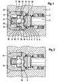
- a pump housing 1 in which a Piston seal 2 sealed a pump piston 3 out is.
- the piston 3 is from an eccentric, not shown moved to the left in the drawing plane and then from a return spring 4 in its bottom dead center, i. in the drawing plane to the right, pushed back. there follows a foot of the piston 3 of the outer surface, not shown of the eccentric.
- On the piston 3 is preferably located a piston cover 5, which on the left in the drawing piston end can be clamped, so that this cover 5 also can adhere to the piston 3 in a horizontal piston position.
- This in the drawing left end of the return spring 4 is in one Spring pot 6 snapped or clamped, leaving the spring 4 also adhere to the spring cup 6 in a horizontal position remains.
- the right in the drawing end of the return spring 4 can also be locked or jammed with the piston cover 5 his.
- the spring cup 6 itself is in particular with a, cylindrical projection 7 in a corresponding Recess 8 pinched in a valve seat carrier 9 or attached to it in a different way so that it is position independent is held by the valve seat carrier 9.
- the return spring 4 to the Valve seat support 9 in the form of an independently handled Assembly unit tied up, so that these components during assembly the piston pump can be mounted together.
- the valve seat carrier 9 has a stepped through-bore 10, the circumferential rounded end edge of the Seat 11 for a preferred spherical valve body 12th forms.
- the valve body 12 is replaced by a biasing spring 13 pressed against the seat 11, wherein the biasing spring supported with its other end to a spring cage 14.
- the Spring cage 14 itself is with a circumferential surface on a cylinder projection 16 of the valve seat carrier 9, if necessary jammed over beads, bulges or projections 17. Accordingly, the outer surface of the spring cage 14 optionally via further beads or projections 18 on the inner surface a valve cover 19 jammed or pressed his.
- the valve forms including the spring cup 6 and the return spring 4 is a structural unit. To this Unit may possibly even the associated piston 3 and connect the piston cover 5.
- the valve shown in Fig. 1 operates as a pressure valve, wherein the pressure means indicated by a dashed line in Fig. 1 Suction channel 20 and one in the spring pot 6 preferably incorporated filter 21 in the interior of the spring cage 14 can get. From there, the pressure medium, at which is in particular to brake fluid over Openings 22 in the interior of the valve cover 19 and of there between the further beads 18 in an annular channel 23rd reach.
- the spring cage 14 is further with radial Incisions 24 provided, which is a drainage of the pressure medium allow from the annular channel 23 in an annular space 25, connected to a dashed line pressure channel 26, the particular not shown to wheel brakes a controllable braking system can lead.
- the preferably made of aluminum valve cover 19 can with be caulked the pump housing 1, as the embossments 27th demonstrate. The caulking is preferably circumferential and can thus sealing the annular space 25 pressure-tight.
- FIG. 2 The construction of FIG. 2 is compared to FIG. 1 with regard to the attachment of the spring cage 14 and the Pressure fluid guide slightly changed. Deriving the Pressure medium from the interior of the spring cage 14 takes place here via channels that pass through in the valve seat carrier 9 or the valve cover 19 embossed grooves 30 are formed. In order to the flow path for the pressure medium is shorter because this no longer lying in the outside of the spring cage 14 Interior of the valve cover 19 can get.
- the Attachment of valve seat carrier 9 and valve cover 19 takes place again by respective jamming with the pump housing, wherein the lid 19 on the outer surface and the valve seat carrier 9 on the inner circumferential surface of the spring cage 14 can be pressed.
- the grooves 30 can turn as Apertures for pressure damping act, so that the interior of the Cover 19 and the interior of the spring cage 14th (corresponding to Fig. 1 and Fig. 2) to be damping chambers can.
- FIG Invention has been dispensed with a special spring cage 14, so that the biasing spring 13 directly on the ground the valve cover 19 is supported.
- the lid 19 and the valve seat carrier 9 are here pressed directly together.
- the valve seat carrier 9 are in particular radially Indented grooves, the outlet of the pressure medium from the interior of the valve cover 19 in the annulus 25 allow. This results in an advantageous Way of simplifying the design and a more stable Connection of the two parts 9, 10 of the valve.
- FIG. 4 In the embodiment of FIG. 4 was the top of steel drawn spring cage 14 by a solid drawn spring cage 31 replaced aluminum, the sealing force of the valve ensures, while providing support for the Preload spring 13 provides.
- the lid 32 is preferably also made of aluminum, extruded or pulled, and pressed on the spring cage 31, so that a very stable and material-saving construction results.
- the alternatively also as tiered Nozzle 34 may be configured, the pressure medium flow into the pressure channel 26, wherein at the same time also can achieve a damping effect.
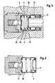
- FIGS. 5 and 6 opposite the embodiments of FIGS. 1 to 4 known changes with respect to the spring pot 36. While in the previous embodiments that facing the valve End of the return spring 4 by pinching or similar Types of attachment at least with the topmost turn was held in the local pot 6, extends at 5 and 6 of the pot 36 to the seal package 2, wherein the seal package 2 at the same time by a radial inwardly facing console 37 held in position becomes. This console 37 is also so far radially inward pulled that the piston cover 5 the interior of the spring cup 36 can not leave, but in the absence Piston on the console 37 abuts (see Fig. 6). In this way, a preloaded, packet-like preassembled unit of spring 4, spring pot 36 and piston cover 5 are created.
- the spring pot 36 is again, as already related described with Figs. 1 to 4, on the circumferential side wall the cylindrical recess 8 of the valve seat carrier 9 pinched, so here is a secure holder for the return spring 4, even when mounted horizontally, in which also the piston can be mounted at the same time can, is possible.
- a suction channel 29 associated with the radial extending passage opening 33 in the spring cup 36 allows the entry of the pressure medium in the working space 40th the pump.
- the Spring pot 36 (as also described in connection with FIGS. 1 to 4) Press in or attach in any other way leaves.
- This spring cup 36 performs several functions. About unspecified fine punched holes or holes in the middle of the bottom of the pot, on the one hand, the Pressure medium filtered in front of the pressure valve. The cylindrical one Outer part of the pot 36 also takes the piston return spring 4 and the piston cover 5 on. After crimping the Console 37, the biased return spring 4 thus in fixed to the interior of the spring cup 36. Im installed Condition fixes the spring pot 36 also with its console 37 nor the seal package 2 in the pump housing.
- FIG. 7 to 10 has a Composition with regard to the spring pot 6, as he related has already been described with Fig. 1 to 4, while the basic structure of the (pressure) valve already from Fig. 3 to 6 is known.
- the main difference to the previous versions is that the interior the valve cover 19 as far as possible to a damping chamber 44 was increased. Nevertheless, the necessary Stability and material strength was the end the lid 19 here via the end edge 41 of the pump housing 1 led out.
- the dashed line drawn contour line 42 shown depending on required or desired size of the damping chamber 44th their outstanding length may be up to the contour line 42 are enlarged.
- the valve seat carrier 9 as in connection with the Top view shown in Fig. 8, for particularly simple Press connection between the valve cover 19 and the valve seat carrier 9 formed as a cold-formed part with polygonal profile so as to be radial in partial areas of the circumference Gap 43 between the valve cover 19 and the valve seat carrier 9 to produce.
- the lid 19 forms its shaping the damping volume of the damping chamber 44.
- the lid 19 can be both cold-formed as also be designed as a rotating part and is usually as well as the pump housing 1 made of aluminum.
- the Aperture function becomes, as already in connection with the figures 1 to 4 described by one or more radial Notches or grooves 30 formed (see also Fig. 2 with associated Description).
- the brake fluid or the pressure medium Flow through the radial gap 43 the brake fluid or the pressure medium to the axial Joint of valve seat support 9 and valve cover 19, where formed by the notch or groove 30 an aperture is.
- the suction channel 29 provides the connection to a suction valve of the pump, not shown, through which the pressure medium is sucked into the pump.
- the pressure valve is used as a preassembled unit with the valve parts 9 and 19, the spring cup 6 and the return spring 4 in the example serving as a valve block pump housing 1 installed.
- the pressure valve and in particular Also provided therefor, formed by the groove 30 Aperture can advantageously by the direction of flow located in front of the pressure valve, in particular provided in the spring cup 6 filter 21 from particles (z. As dirt or chips) from the Druck.-.- or braking system to be protected.
- the filter 21 is preferably made Sheet metal shaped and in particular by means of a press fit attached to the valve seat carrier 9. As already above in the In connection with Figs.
- the size of the required volume for the damping chamber 44 cause (as already in Connected with Fig. 7 indicated) that the bottom of Valve cover 19 from the relatively small pump housing protrudes.
- This can be done according to a training take advantage of the invention by extending the lengthened Approach 47 of the valve cover 19 as an additional breakpoint for the attachment of the pump housing or a hydraulic-electronic Control of the brake system on the vehicle starts.
- a rubber damper 48 be pushed onto the projection 47 of the valve cover 19, in the then, for example, a blank holder 49 is knotted can be.
- the illustrated geometry of holder 49 and Rubber damper 48 according to FIG. 9 is only an example.
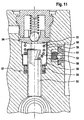
- the Au Installationsform of FIG. 11 shows a development of the present invention to even larger assemblies which are used to assemble a mass product pump can be mounted easily and inexpensively can.
- the return spring 51 is the piston 52 out with spring coils provided that reduce in diameter.
- the piston 52 at its upper end be provided with a suitable undercut 53, in which the spring 51 can be engaged.
- the shown Possibility of a conical undercut 53 is only exemplary.
- the undercut can also come from a groove with a quadrangular or part-circular contour or one hemispherical contour exist.
- the return spring 51 is, as in the previous Embodiments described over a spring pot or also attached directly to the valve seat carrier 54 (not shown), such as by snapping or jamming.
- the pump housing can in addition to the spring cup or else as its special training a spacer 55 is inserted be who with his console 56, the gasket 57 and a piston seal 60 holds in position, wherein the spacer 55 as well as the one described above Spring cup can be supported on the valve seat carrier 54 or the spacer 55 itself formed as a spring cup can be.
- the packing 57 includes as in all Embodiments of the present invention, a piston seal 60 and an unspecified support ring.
- the spacer or spring cup 55 is preferably at least in the region of a suction channel 58 with a sieve or Filter 59 provided or designed as a filter 59, so that he also a filter function for the flowing through Exerts pressure medium.
- the spacer 55 with the filter function Can be both as a stamped part or as a plastic part be educated. But it is also possible, as related explained with the spring pot 6 above, in the Valve seat carrier 54 in FIG. 11, not shown undercuts mold in which the upper in the drawing End of the return spring 51 can engage. This will achieved according to the invention a pre-assembly, in addition the valve and the spring 51 also include the piston 52 can. It is not necessary that the spring 51 engages from the outside in the undercut 53 of the piston. Rather, the piston 52 as shown on the left side of Fig. 11 also with a in the Be provided drawing from above coming hole, in provided a radially outwardly directed undercut is, in which the introduced in this hole Spring 51 snaps into place.
- a suction valve is indicated at 61.
- this suction valve 61 in all embodiments as of pressure valve, return spring 4, 51 and piston 3.52 separate component formed.
- the suction valve 61 is in particular fixed by caulking in the pump housing 1 and together with this one is easy to handle and unit that can be tested separately from the pressure valve.
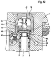
- FIG. 1 is the pump piston 3 again in the pump housing 1 guided sealed over the piston seal 2.
- the pump piston 3 can with particular advantage, as well as in the preceding examples, a needle or needle roller be a commercial rolling or needle bearing.
- the piston 3 is thus formed as a solid piston 3.
- Such a piston 3 has a surface with special quality, with regard to wear and sealing has excellent properties.
- needles a warehouse as a mass-produced particularly cost-effective.
- the pressure valve again comprises the valve seat carrier 9, on the valve seat 11 is provided with the particular designed as a ball valve body 12 cooperates.
- the valve body 12 is by means of the spring 13 against the valve seat 11 biased, with the spring 13 with her another end to a spring cage 62 is supported, the one unsigned guide for the spring 13 has.
- the Spring cage 62 is analogous to the previous embodiments attached to the valve cover 19, for example by Pressing.
- the spring cup 36 is provided, preferably connected to the valve seat carrier 9 is.
- the piston seal 2 directed towards End of the spring cup 36 analogous to in Fig. 5 and 6 illustrated embodiment, one to the piston 3 out directed console 37, which provided the seal 2 at its Holding position.
- the consoles 37 act provided with on the piston cover 5, outwardly projecting radial Projections together, so that the pressure valve, the Spring pot 36, the piston cover 5 and the return spring. 4 as a self-contained unit in the pump housing 1 can be installed.
- the return spring 4 indirectly via the spring cup 36 on Valve seat carrier 9 attached.
- a filter 63 is provided on the valve seat carrier 9 its not here with the pen pot 36, but rather is designed as a separate component.
Landscapes
- Engineering & Computer Science (AREA)
- Mechanical Engineering (AREA)
- General Engineering & Computer Science (AREA)
- Physics & Mathematics (AREA)
- Fluid Mechanics (AREA)
- Transportation (AREA)
- Details Of Reciprocating Pumps (AREA)
- Valves And Accessory Devices For Braking Systems (AREA)
- Reciprocating Pumps (AREA)
- Regulating Braking Force (AREA)
Description
- Fig. 1 - 2
- im Längsschnitt erste Ausführungsbeispiele der vorliegenden Erfindung mit einem Druckventil, in dem ein Federkäfig angeordnet ist,
- Fig. 3 - 4
- ebenfalls in einer geschnittenen Ansicht weitere mögliche Ausgestaltungen des Druckventils,
- Fig. 5 - 6
- ein weiteres Ausführungsbeispiel im Schnitt, wobei erfindungsgemäß eine Rückstellfeder für einen Kolben am Druckventil befestigt ist,
- Fig. 7 - 10
- im Längsschnitt eine Variante, bei der im Druckventil eine Dämpfungskammer vorgesehen ist,
- Fig. 11
- in geschnittener Ansicht eine Weiterbildung der vorliegenden Erfindung, bei der die Rückstellfeder zusätzlich mit dem Kolben verbunden ist, und
- Fig. 12
- ein bevorzugtes Ausführungsbeispiel der Erfindung mit einem vom Federtopf separat ausgebildeten Filter, ebenfalls im Schnitt.
Claims (11)
- Kolbenpumpe, insbesondere für regelbare Bremssysteme, bei der ein Arbeitsraum (40) der Pumpe vor einem Kolben (3, 52) durch ein Druckventil abgegrenzt ist, wobei eine Rückstellfeder (4, 51) sich mit ihrem einen Ende an einem Ventilsitzträger (9, 54) des Druckventils abstützt und mit ihrem anderen Ende den Kolben (3, 52) in seine untere Totpunktlage zurückstellt, dadurch gekennzeichnet, dass die Rückstellfeder (4, 51) an ihrem einen Ende indirekt über einen Federtopf (6,36,55) am Ventilsitzträger (9, 54) befestigt ist.
- Kolbenpumpe nach Anspruch 1, dadurch gekennzeichnet, dass der Federtopf (6, 36, 55) mit zumindest einem Abschnitt seiner Außenfläche an der Innenwand einer Ausnehmung (8) des Ventilsitzträgers (9, 54) gehalten ist.
- Kolbenpumpe nach Anspruch 1 oder 2, dadurch gekennzeichnet, dass der Federtopf (36, 55) an seinem zum Kolben (3, 52) hin gerichteten Ende eine radial nach innen gerichtete Konsole (37, 56) aufweist.
- Kolbenpumpe nach Anspruch 3, dadurch gekennzeichnet, dass die Konsole (37, 56) einen Anschlag für eine im Pumpengehäuse (1) angeordnete Kolbendichtung (2, 60) bildet.
- Kolbenpumpe nach einem der vorangegangenen Ansprüche, dadurch gekennzeichnet, dass am Federtopf (6, 36, 55) separat oder einstückig ein Filter (21, 59, 63) vorgesehen ist.
- Kolbenpumpe nach einem der vorangegangenen Ansprüche, dadurch gekennzeichnet, dass als Kolben (3, 52) die Nadel eines handelsüblichen Nadellagers vorgesehen ist.
- Kolbenpumpe nach einem der vorangegangenen Ansprüche, dadurch gekennzeichnet, dass im Pumpengehäuse (1) ein Saugventil (61) vorgesehen ist, das vom Druckventil, der Rückstellfeder (4, 51), dem Federtopf (6, 36, 55) und dem Kolben (3, 52) unabhängig montier- und prüfbar ist.
- Kolbenpumpe nach einem der vorangegangenen Ansprüche, dadurch gekennzeichnet, dass die Rückstellfeder (51) mit dem Pumpenkolben (52) verbunden ist.
- Kolbenpumpe nach einem der vorangegangenen Ansprüche, dadurch gekennzeichnet, dass das Druckventil einen Ventildeckel (19) aufweist, in dem eine Dämpfungskammer (44) vorgesehen ist.
- Kolbenpumpe nach Anspruch 1, dadurch gekennzeichnet, dass eine vormontierte Einheit vorgesehen ist, welche eine vorgespannte Rückstellfeder (4), einen Federtopf (36) und einen Kolbendeckel (5) umfasst.
- Kolbenpumpe nach Anspruch 4, dadurch gekennzeichnet, dass die Konsole (37) als Anschlag für den Kolbendeckel (5) vorgesehen ist.
Applications Claiming Priority (3)
| Application Number | Priority Date | Filing Date | Title |
|---|---|---|---|
| DE10013858 | 2000-03-21 | ||
| DE10013858A DE10013858A1 (de) | 2000-03-21 | 2000-03-21 | Kolbenpumpe mit Ventil-Montageeinheit |
| PCT/EP2001/003049 WO2001070550A2 (de) | 2000-03-21 | 2001-03-16 | Kolbenpumpe |
Publications (2)
| Publication Number | Publication Date |
|---|---|
| EP1268248A2 EP1268248A2 (de) | 2003-01-02 |
| EP1268248B1 true EP1268248B1 (de) | 2004-06-02 |
Family
ID=7635683
Family Applications (1)
| Application Number | Title | Priority Date | Filing Date |
|---|---|---|---|
| EP01936090A Expired - Lifetime EP1268248B1 (de) | 2000-03-21 | 2001-03-16 | Kolbenpumpe |
Country Status (8)
| Country | Link |
|---|---|
| US (1) | US6866489B2 (de) |
| EP (1) | EP1268248B1 (de) |
| JP (1) | JP4795606B2 (de) |
| KR (1) | KR100757284B1 (de) |
| CN (1) | CN1192927C (de) |
| BR (1) | BR0109350B1 (de) |
| DE (2) | DE10013858A1 (de) |
| WO (1) | WO2001070550A2 (de) |
Cited By (1)
| Publication number | Priority date | Publication date | Assignee | Title |
|---|---|---|---|---|
| US9017044B2 (en) | 2011-03-25 | 2015-04-28 | Aisin Aw Co., Ltd. | Electromagnetic pump |
Families Citing this family (48)
| Publication number | Priority date | Publication date | Assignee | Title |
|---|---|---|---|---|
| KR20040011142A (ko) * | 2002-07-29 | 2004-02-05 | 주식회사 만도 | 스티어링장치의 댐핑밸브 |
| DE50309273D1 (de) | 2002-09-24 | 2008-04-10 | Continental Teves Ag & Co Ohg | Fördervorrichtung |
| DE10244373B4 (de) * | 2002-09-24 | 2011-08-11 | Continental Teves AG & Co. OHG, 60488 | Kolbenpumpe |
| DE10346237A1 (de) * | 2003-02-12 | 2004-09-09 | Continental Teves Ag & Co. Ohg | Kolbenpumpe |
| DE102004037140A1 (de) * | 2004-07-30 | 2006-03-23 | Robert Bosch Gmbh | Kolbenpumpe mit verbessertem Wirkungsgrad |
| JP4710636B2 (ja) * | 2006-02-07 | 2011-06-29 | 株式会社アドヴィックス | フィルタを用いたピストンポンプ及びバルブシート部材へのフィルタ組み付け方法 |
| DE102006035708A1 (de) * | 2006-08-01 | 2008-02-07 | Robert Bosch Gmbh | Fahrzeugbremsanlagen-Kolbenpumpe mit einem Kolben |
| KR100682323B1 (ko) * | 2006-12-29 | 2007-02-16 | 일우산업 주식회사 | 전기히터를 이용한 초소형 난방장치 |
| KR100882791B1 (ko) * | 2007-04-09 | 2009-02-09 | 주식회사 만도 | 전자제어식 브레이크 시스템용 펌프 |
| KR100827272B1 (ko) * | 2007-04-09 | 2008-05-07 | 주식회사 만도 | 전자제어식 브레이크 시스템용 펌프 |
| US20080245069A1 (en) * | 2007-04-09 | 2008-10-09 | Mando Corporation | Pump of electronically controlled brake system |
| KR100888184B1 (ko) * | 2007-04-09 | 2009-03-10 | 주식회사 만도 | 전자제어식 브레이크 시스템용 펌프 |
| JP2008286083A (ja) * | 2007-05-17 | 2008-11-27 | Nissin Kogyo Co Ltd | プランジャポンプ |
| DE102007049152A1 (de) * | 2007-10-12 | 2009-04-16 | Robert Bosch Gmbh | Hydraulische Kolbenpumpe |
| KR101405380B1 (ko) * | 2007-12-18 | 2014-06-10 | 현대모비스 주식회사 | 차량의 피스톤펌프 |
| DE102008029245A1 (de) | 2008-02-28 | 2009-09-03 | Continental Teves Ag & Co. Ohg | Fahrzeugbremsanlagenkolbenpumpe |
| JP5682867B2 (ja) * | 2009-09-29 | 2015-03-11 | Ntn株式会社 | 密封型転がり軸受 |
| DE102009046372A1 (de) * | 2009-11-04 | 2011-05-05 | Robert Bosch Gmbh | Ventil mit einem kugelartigen Dichtelement |
| DE102009046577A1 (de) * | 2009-11-10 | 2011-05-12 | Robert Bosch Gmbh | Ventil einer Kolbenpumpe mit einem Ventilschließkörper |
| DE102010040329A1 (de) * | 2010-09-07 | 2012-03-08 | Robert Bosch Gmbh | Pumpenelement einer Kolbenpumpe mit einem Ventil |
| DE102010063322A1 (de) * | 2010-12-17 | 2012-07-05 | Robert Bosch Gmbh | Kolbenpumpe mit einer Halterung |
| JP5662837B2 (ja) * | 2011-02-24 | 2015-02-04 | 日信工業株式会社 | プランジャポンプおよびプランジャポンプの製造方法 |
| DE102012005391B4 (de) * | 2011-03-11 | 2013-11-28 | Mando Corporation | Absperrventil für hydraulisches Bremssystem |
| KR101237320B1 (ko) * | 2011-03-11 | 2013-02-28 | 주식회사 만도 | 브레이크 시스템의 체크 밸브 |
| DE102011079636A1 (de) * | 2011-07-22 | 2013-01-24 | Robert Bosch Gmbh | Pumpenelement für eine hydraulische Kolbenpumpe |
| JP5579686B2 (ja) * | 2011-11-17 | 2014-08-27 | 日信工業株式会社 | プランジャポンプ |
| DE102011087090A1 (de) * | 2011-11-25 | 2013-05-29 | Robert Bosch Gmbh | Hydraulisch gesteuertes Speicherkammerventil |
| KR20130089368A (ko) * | 2012-02-02 | 2013-08-12 | 주식회사 만도 | 브레이크 시스템의 체크 밸브 |
| DE102012207000A1 (de) * | 2012-04-27 | 2013-10-31 | Continental Teves Ag & Co. Ohg | Kolbenpumpe |
| DE102012222826A1 (de) * | 2012-06-28 | 2014-01-02 | Robert Bosch Gmbh | Kolben-Kraftstoffpumpe |
| DE102012213022A1 (de) * | 2012-07-25 | 2014-01-30 | Robert Bosch Gmbh | Vorrichtung zur Drosselung einer Fluidströmung und korrespondierende Kolbenpumpe zur Förderung von Fluiden |
| DE102013219428A1 (de) * | 2013-09-26 | 2015-03-26 | Continental Automotive Gmbh | Dämpfer für eine Hochdruckpumpe |
| DE102014212646B4 (de) * | 2014-04-15 | 2025-03-20 | Robert Bosch Gmbh | Kraftstoff-Hochdruckpumpe, mit einem Auslassventil mit einem Ventilkörper und einer Ventilkugel |
| WO2016004920A2 (de) * | 2014-07-11 | 2016-01-14 | Hilite Germany Gmbh | Ventil, insbesondere hydraulikventil |
| KR101567842B1 (ko) * | 2014-09-12 | 2015-11-11 | 현대모비스 주식회사 | 차량용 제동장치 |
| JP6389722B2 (ja) * | 2014-09-30 | 2018-09-12 | 日信工業株式会社 | ソレノイドポンプ |
| CN106194708B (zh) * | 2015-04-29 | 2020-03-06 | 罗伯特·博世有限公司 | 柱塞式高压泵及其高压组件、阀组件 |
| US10753491B2 (en) * | 2015-09-25 | 2020-08-25 | Bloechlinger Engineering Ag | Check valve |
| DE102016204002A1 (de) * | 2016-03-11 | 2017-09-14 | Robert Bosch Gmbh | Kolbenpumpe, insbesondere als Druckerzeuger in einer elektronisch schlupfregelbaren Fahrzeugbremsanlage |
| KR101915501B1 (ko) * | 2016-07-25 | 2018-11-08 | 이래에이엠에스 주식회사 | 차량의 브레이크 시스템용 피스톤 펌프 |
| DE102016220610A1 (de) * | 2016-10-20 | 2018-04-26 | Robert Bosch Gmbh | Hochdruckpumpe für ein Kraftstoffeinspritzsystem |
| KR102390511B1 (ko) * | 2017-07-31 | 2022-04-26 | 현대모비스 주식회사 | 전자제어식 브레이크 시스템용 펌프장치 |
| DE102017216900A1 (de) * | 2017-09-25 | 2019-03-28 | Robert Bosch Gmbh | Druckmittelsteuerventil, insbesondere zur Steuerung einer Durchströmungsrichtung in einem Druckmittelkreis und Kolbenpumpe, insbesondere zur Förderung eines Druckmittels in einer elektronisch schlupfregelbaren Fahrzeugbremsanlage |
| JP2019116155A (ja) * | 2017-12-27 | 2019-07-18 | ロベルト・ボッシュ・ゲゼルシャフト・ミト・ベシュレンクテル・ハフツングRobert Bosch Gmbh | ブレーキ液圧制御装置 |
| CN110481528B (zh) * | 2018-10-24 | 2020-11-06 | 京西重工(上海)有限公司 | 液压控制单元 |
| DE102019201536A1 (de) * | 2019-02-07 | 2020-08-13 | Robert Bosch Gmbh | Elektrohydraulische Fremdkraft-Fahrzeugbremsanlage |
| DE102019207686A1 (de) * | 2019-05-25 | 2020-11-26 | Robert Bosch Gmbh | Hydroaggregat, insbesondere zur Versorgung eines Bremskreises einer Fahrzeugbremsanlage mit Druckmittel unter Bremsdruck |
| CN112360713B (zh) * | 2020-10-23 | 2021-06-11 | 宁波赛福汽车制动有限公司 | 一种汽车柱塞泵系统 |
Family Cites Families (15)
| Publication number | Priority date | Publication date | Assignee | Title |
|---|---|---|---|---|
| JPH06323241A (ja) * | 1993-05-14 | 1994-11-22 | Sumitomo Electric Ind Ltd | プランジャポンプ |
| DE9319462U1 (de) * | 1993-12-17 | 1995-04-27 | Lucas Industries Public Limited Company, Solihull, West Midlands | Kolbenpumpe zum Fördern von Hydraulikflüssigkeit in einer blockiergeschützten Fahrzeugbremsanlage |
| JPH0840234A (ja) * | 1994-07-29 | 1996-02-13 | Aisin Seiki Co Ltd | 車両用液圧ブレーキ装置 |
| US5538335A (en) * | 1994-07-29 | 1996-07-23 | Aisin Seiki Kabushiki Kaisha | Hydraulic brake system for a vehicle having a pump and a reservoir |
| DE19527401A1 (de) * | 1995-07-27 | 1997-01-30 | Teves Gmbh Alfred | Kolbenpumpe |
| WO1999006697A1 (de) * | 1997-07-30 | 1999-02-11 | Robert Bosch Gmbh | Rohrförmiger kolben und verschlussstopfen für eine radialkolbenpumpe, hergestellt durch kaltumformen |
| DE19732817B4 (de) * | 1997-07-30 | 2005-06-30 | Robert Bosch Gmbh | Kolbenpumpe |
| DE19743186B4 (de) * | 1997-09-30 | 2007-04-12 | Continental Teves Ag & Co. Ohg | Kolbenpumpe für Hydraulikflüssigkeit |
| DE19800499A1 (de) * | 1998-01-09 | 1999-07-15 | Bosch Gmbh Robert | Kolbenpumpe |
| US6622751B1 (en) * | 1998-02-09 | 2003-09-23 | Continental Teves Ag & Co., Ohg | Pressure valve for a reciprocating pump |
| DE19816289A1 (de) | 1998-02-09 | 1999-08-12 | Itt Mfg Enterprises Inc | Druckventil, insbesondere für eine Kolbenpumpe |
| DE19820902A1 (de) * | 1998-05-09 | 1999-11-11 | Bosch Gmbh Robert | Kolbenpumpe |
| FR2784719B1 (fr) * | 1998-10-15 | 2002-09-06 | Bosch Gmbh Robert | Pompe a piston |
| DE19914065A1 (de) * | 1999-03-27 | 2000-09-28 | Bosch Gmbh Robert | Kolbenpumpe |
| DE19928913A1 (de) * | 1999-06-24 | 2001-01-04 | Bosch Gmbh Robert | Kolbenpumpe |
-
2000
- 2000-03-21 DE DE10013858A patent/DE10013858A1/de not_active Withdrawn
-
2001
- 2001-03-16 CN CNB018067565A patent/CN1192927C/zh not_active Expired - Fee Related
- 2001-03-16 EP EP01936090A patent/EP1268248B1/de not_active Expired - Lifetime
- 2001-03-16 WO PCT/EP2001/003049 patent/WO2001070550A2/de not_active Ceased
- 2001-03-16 US US10/239,552 patent/US6866489B2/en not_active Expired - Lifetime
- 2001-03-16 JP JP2001568773A patent/JP4795606B2/ja not_active Expired - Fee Related
- 2001-03-16 KR KR1020027011910A patent/KR100757284B1/ko not_active Expired - Fee Related
- 2001-03-16 DE DE50102471T patent/DE50102471D1/de not_active Expired - Lifetime
- 2001-03-16 BR BRPI0109350-9A patent/BR0109350B1/pt not_active IP Right Cessation
Cited By (2)
| Publication number | Priority date | Publication date | Assignee | Title |
|---|---|---|---|---|
| US9017044B2 (en) | 2011-03-25 | 2015-04-28 | Aisin Aw Co., Ltd. | Electromagnetic pump |
| DE112012000105B4 (de) * | 2011-03-25 | 2015-06-25 | Aisin Aw Co., Ltd. | Elektromagnetische Pumpe mit einem beweglichen Kolben und einem Einlassventil in einem Stützbauteil |
Also Published As
| Publication number | Publication date |
|---|---|
| US6866489B2 (en) | 2005-03-15 |
| DE10013858A1 (de) | 2001-09-27 |
| CN1418158A (zh) | 2003-05-14 |
| BR0109350B1 (pt) | 2009-12-01 |
| JP2003528244A (ja) | 2003-09-24 |
| KR100757284B1 (ko) | 2007-09-11 |
| DE50102471D1 (de) | 2004-07-08 |
| EP1268248A2 (de) | 2003-01-02 |
| WO2001070550A2 (de) | 2001-09-27 |
| US20030053920A1 (en) | 2003-03-20 |
| BR0109350A (pt) | 2002-12-03 |
| KR20020081430A (ko) | 2002-10-26 |
| CN1192927C (zh) | 2005-03-16 |
| JP4795606B2 (ja) | 2011-10-19 |
| WO2001070550A3 (de) | 2002-02-07 |
Similar Documents
| Publication | Publication Date | Title |
|---|---|---|
| EP1268248A2 (de) | Kolbenpumpe | |
| DE19732817B4 (de) | Kolbenpumpe | |
| EP0734494B2 (de) | Kolbenpumpe zum fördern von hydraulikflüssigkeit | |
| DE60101512T2 (de) | Axialwälzlager für eine Fahrzeugaufhängung mit Rückhaltemittel | |
| EP1030973B1 (de) | Kolbenpumpe | |
| EP0861376B1 (de) | Kolbenpumpe | |
| DE19960335A1 (de) | Hydraulikzylinder | |
| DE60320607T2 (de) | Einheit zur Verpackung und zur Ausgabe eines Produkts, insbesondere in Form einer Probe | |
| DE19951665A1 (de) | Elektromagnetventil, insbesondere für hydraulische Bremsanlagen mit Schlupfregelung | |
| EP1022467A2 (de) | Kolbenpumpe | |
| EP0932760A1 (de) | Verliersicherung mit filter für einen kolben einer radialkolbenpumpe | |
| WO1994012789A1 (de) | Ventil, insbesondere druckventil für eine radialkolbenpumpe, mit wenigen komponenten | |
| EP0607370B2 (de) | Kolben mit zentralventil für hydraulische bremsanlagen | |
| EP3452344A1 (de) | Hydraulikzylinder, insbesondere hauptbremszylinder für hydraulische bremsanlagen | |
| DE102012018301A1 (de) | Filter und Halterungsanordnung für Kolbenpumpe | |
| DE19742611A1 (de) | Kolbenpumpe | |
| EP0850166B1 (de) | Geberzylinder | |
| DE602004003261T2 (de) | Hydraulischer Hauptzylinder für ein Fahrzeug | |
| DE102004048670A1 (de) | Hauptzylinder | |
| DE102009006042A1 (de) | Kolbenpumpe, insbesondere zur Versorgung elektrohydraulischer Bremssysteme | |
| DE102010030665B4 (de) | Stützring, insbesondere für eine Fluidbaugruppe in einem Fahrzeug | |
| DE19712147A1 (de) | Kolbenpumpe | |
| DE2925954C2 (de) | Hydraulisches Drucksteuerventil für ein Kraftfahrzeugbremssystem | |
| WO2012150347A1 (de) | Hauptzylinder insbesondere für ein geregeltes bremssystem | |
| DE102005058526B4 (de) | Zweistufiges Ventil zum Steuern von Fluiden |
Legal Events
| Date | Code | Title | Description |
|---|---|---|---|
| PUAI | Public reference made under article 153(3) epc to a published international application that has entered the european phase |
Free format text: ORIGINAL CODE: 0009012 |
|
| 17P | Request for examination filed |
Effective date: 20021021 |
|
| AK | Designated contracting states |
Kind code of ref document: A2 Designated state(s): AT BE CH CY DE DK ES FI FR GB GR IE IT LI LU MC NL PT SE TR |
|
| 17Q | First examination report despatched |
Effective date: 20030319 |
|
| GRAP | Despatch of communication of intention to grant a patent |
Free format text: ORIGINAL CODE: EPIDOSNIGR1 |
|
| GRAS | Grant fee paid |
Free format text: ORIGINAL CODE: EPIDOSNIGR3 |
|
| GRAA | (expected) grant |
Free format text: ORIGINAL CODE: 0009210 |
|
| AK | Designated contracting states |
Kind code of ref document: B1 Designated state(s): DE ES FR GB IT |
|
| PG25 | Lapsed in a contracting state [announced via postgrant information from national office to epo] |
Ref country code: GB Free format text: LAPSE BECAUSE OF FAILURE TO SUBMIT A TRANSLATION OF THE DESCRIPTION OR TO PAY THE FEE WITHIN THE PRESCRIBED TIME-LIMIT Effective date: 20040602 |
|
| REG | Reference to a national code |
Ref country code: GB Ref legal event code: FG4D Free format text: NOT ENGLISH |
|
| REF | Corresponds to: |
Ref document number: 50102471 Country of ref document: DE Date of ref document: 20040708 Kind code of ref document: P |
|
| REG | Reference to a national code |
Ref country code: IE Ref legal event code: FG4D Free format text: GERMAN |
|
| PG25 | Lapsed in a contracting state [announced via postgrant information from national office to epo] |
Ref country code: ES Free format text: LAPSE BECAUSE OF FAILURE TO SUBMIT A TRANSLATION OF THE DESCRIPTION OR TO PAY THE FEE WITHIN THE PRESCRIBED TIME-LIMIT Effective date: 20040913 |
|
| GBV | Gb: ep patent (uk) treated as always having been void in accordance with gb section 77(7)/1977 [no translation filed] |
Effective date: 20040602 |
|
| ET | Fr: translation filed | ||
| REG | Reference to a national code |
Ref country code: IE Ref legal event code: FD4D |
|
| PLBE | No opposition filed within time limit |
Free format text: ORIGINAL CODE: 0009261 |
|
| STAA | Information on the status of an ep patent application or granted ep patent |
Free format text: STATUS: NO OPPOSITION FILED WITHIN TIME LIMIT |
|
| 26N | No opposition filed |
Effective date: 20050303 |
|
| REG | Reference to a national code |
Ref country code: FR Ref legal event code: PLFP Year of fee payment: 16 |
|
| REG | Reference to a national code |
Ref country code: FR Ref legal event code: PLFP Year of fee payment: 17 |
|
| REG | Reference to a national code |
Ref country code: FR Ref legal event code: PLFP Year of fee payment: 18 |
|
| PGFP | Annual fee paid to national office [announced via postgrant information from national office to epo] |
Ref country code: DE Payment date: 20180331 Year of fee payment: 18 |
|
| PGFP | Annual fee paid to national office [announced via postgrant information from national office to epo] |
Ref country code: IT Payment date: 20190325 Year of fee payment: 19 Ref country code: FR Payment date: 20190322 Year of fee payment: 19 |
|
| REG | Reference to a national code |
Ref country code: DE Ref legal event code: R119 Ref document number: 50102471 Country of ref document: DE |
|
| PG25 | Lapsed in a contracting state [announced via postgrant information from national office to epo] |
Ref country code: DE Free format text: LAPSE BECAUSE OF NON-PAYMENT OF DUE FEES Effective date: 20191001 |
|
| PG25 | Lapsed in a contracting state [announced via postgrant information from national office to epo] |
Ref country code: FR Free format text: LAPSE BECAUSE OF NON-PAYMENT OF DUE FEES Effective date: 20200331 |
|
| PG25 | Lapsed in a contracting state [announced via postgrant information from national office to epo] |
Ref country code: IT Free format text: LAPSE BECAUSE OF NON-PAYMENT OF DUE FEES Effective date: 20200316 |