EP1265700B1 - Reacteur d'optimisation de procede a ecoulement parallele - Google Patents
Reacteur d'optimisation de procede a ecoulement parallele Download PDFInfo
- Publication number
- EP1265700B1 EP1265700B1 EP01914751A EP01914751A EP1265700B1 EP 1265700 B1 EP1265700 B1 EP 1265700B1 EP 01914751 A EP01914751 A EP 01914751A EP 01914751 A EP01914751 A EP 01914751A EP 1265700 B1 EP1265700 B1 EP 1265700B1
- Authority
- EP
- European Patent Office
- Prior art keywords
- flow
- flow restrictors
- feed
- reactors
- inlet
- Prior art date
- Legal status (The legal status is an assumption and is not a legal conclusion. Google has not performed a legal analysis and makes no representation as to the accuracy of the status listed.)
- Expired - Lifetime
Links
Images


Classifications
-
- B—PERFORMING OPERATIONS; TRANSPORTING
- B01—PHYSICAL OR CHEMICAL PROCESSES OR APPARATUS IN GENERAL
- B01L—CHEMICAL OR PHYSICAL LABORATORY APPARATUS FOR GENERAL USE
- B01L7/00—Heating or cooling apparatus; Heat insulating devices
- B01L7/52—Heating or cooling apparatus; Heat insulating devices with provision for submitting samples to a predetermined sequence of different temperatures, e.g. for treating nucleic acid samples
- B01L7/525—Heating or cooling apparatus; Heat insulating devices with provision for submitting samples to a predetermined sequence of different temperatures, e.g. for treating nucleic acid samples with physical movement of samples between temperature zones
-
- B—PERFORMING OPERATIONS; TRANSPORTING
- B01—PHYSICAL OR CHEMICAL PROCESSES OR APPARATUS IN GENERAL
- B01J—CHEMICAL OR PHYSICAL PROCESSES, e.g. CATALYSIS OR COLLOID CHEMISTRY; THEIR RELEVANT APPARATUS
- B01J19/00—Chemical, physical or physico-chemical processes in general; Their relevant apparatus
- B01J19/0006—Controlling or regulating processes
- B01J19/004—Multifunctional apparatus for automatic manufacturing of various chemical products
-
- B—PERFORMING OPERATIONS; TRANSPORTING
- B01—PHYSICAL OR CHEMICAL PROCESSES OR APPARATUS IN GENERAL
- B01J—CHEMICAL OR PHYSICAL PROCESSES, e.g. CATALYSIS OR COLLOID CHEMISTRY; THEIR RELEVANT APPARATUS
- B01J19/00—Chemical, physical or physico-chemical processes in general; Their relevant apparatus
- B01J19/0046—Sequential or parallel reactions, e.g. for the synthesis of polypeptides or polynucleotides; Apparatus and devices for combinatorial chemistry or for making molecular arrays
-
- B—PERFORMING OPERATIONS; TRANSPORTING
- B01—PHYSICAL OR CHEMICAL PROCESSES OR APPARATUS IN GENERAL
- B01J—CHEMICAL OR PHYSICAL PROCESSES, e.g. CATALYSIS OR COLLOID CHEMISTRY; THEIR RELEVANT APPARATUS
- B01J19/00—Chemical, physical or physico-chemical processes in general; Their relevant apparatus
- B01J19/0093—Microreactors, e.g. miniaturised or microfabricated reactors
-
- B—PERFORMING OPERATIONS; TRANSPORTING
- B01—PHYSICAL OR CHEMICAL PROCESSES OR APPARATUS IN GENERAL
- B01J—CHEMICAL OR PHYSICAL PROCESSES, e.g. CATALYSIS OR COLLOID CHEMISTRY; THEIR RELEVANT APPARATUS
- B01J4/00—Feed or outlet devices; Feed or outlet control devices
-
- B—PERFORMING OPERATIONS; TRANSPORTING
- B01—PHYSICAL OR CHEMICAL PROCESSES OR APPARATUS IN GENERAL
- B01L—CHEMICAL OR PHYSICAL LABORATORY APPARATUS FOR GENERAL USE
- B01L3/00—Containers or dishes for laboratory use, e.g. laboratory glassware; Droppers
- B01L3/50—Containers for the purpose of retaining a material to be analysed, e.g. test tubes
- B01L3/502—Containers for the purpose of retaining a material to be analysed, e.g. test tubes with fluid transport, e.g. in multi-compartment structures
- B01L3/5025—Containers for the purpose of retaining a material to be analysed, e.g. test tubes with fluid transport, e.g. in multi-compartment structures for parallel transport of multiple samples
-
- B—PERFORMING OPERATIONS; TRANSPORTING
- B01—PHYSICAL OR CHEMICAL PROCESSES OR APPARATUS IN GENERAL
- B01L—CHEMICAL OR PHYSICAL LABORATORY APPARATUS FOR GENERAL USE
- B01L3/00—Containers or dishes for laboratory use, e.g. laboratory glassware; Droppers
- B01L3/50—Containers for the purpose of retaining a material to be analysed, e.g. test tubes
- B01L3/502—Containers for the purpose of retaining a material to be analysed, e.g. test tubes with fluid transport, e.g. in multi-compartment structures
- B01L3/5027—Containers for the purpose of retaining a material to be analysed, e.g. test tubes with fluid transport, e.g. in multi-compartment structures by integrated microfluidic structures, i.e. dimensions of channels and chambers are such that surface tension forces are important, e.g. lab-on-a-chip
- B01L3/502746—Containers for the purpose of retaining a material to be analysed, e.g. test tubes with fluid transport, e.g. in multi-compartment structures by integrated microfluidic structures, i.e. dimensions of channels and chambers are such that surface tension forces are important, e.g. lab-on-a-chip characterised by the means for controlling flow resistance, e.g. flow controllers, baffles
-
- B—PERFORMING OPERATIONS; TRANSPORTING
- B01—PHYSICAL OR CHEMICAL PROCESSES OR APPARATUS IN GENERAL
- B01L—CHEMICAL OR PHYSICAL LABORATORY APPARATUS FOR GENERAL USE
- B01L7/00—Heating or cooling apparatus; Heat insulating devices
- B01L7/54—Heating or cooling apparatus; Heat insulating devices using spatial temperature gradients
-
- B—PERFORMING OPERATIONS; TRANSPORTING
- B01—PHYSICAL OR CHEMICAL PROCESSES OR APPARATUS IN GENERAL
- B01J—CHEMICAL OR PHYSICAL PROCESSES, e.g. CATALYSIS OR COLLOID CHEMISTRY; THEIR RELEVANT APPARATUS
- B01J2219/00—Chemical, physical or physico-chemical processes in general; Their relevant apparatus
- B01J2219/00002—Chemical plants
- B01J2219/00027—Process aspects
- B01J2219/00038—Processes in parallel
-
- B—PERFORMING OPERATIONS; TRANSPORTING
- B01—PHYSICAL OR CHEMICAL PROCESSES OR APPARATUS IN GENERAL
- B01J—CHEMICAL OR PHYSICAL PROCESSES, e.g. CATALYSIS OR COLLOID CHEMISTRY; THEIR RELEVANT APPARATUS
- B01J2219/00—Chemical, physical or physico-chemical processes in general; Their relevant apparatus
- B01J2219/00274—Sequential or parallel reactions; Apparatus and devices for combinatorial chemistry or for making arrays; Chemical library technology
- B01J2219/00277—Apparatus
- B01J2219/00279—Features relating to reactor vessels
- B01J2219/00306—Reactor vessels in a multiple arrangement
- B01J2219/00313—Reactor vessels in a multiple arrangement the reactor vessels being formed by arrays of wells in blocks
- B01J2219/00315—Microtiter plates
- B01J2219/00317—Microwell devices, i.e. having large numbers of wells
-
- B—PERFORMING OPERATIONS; TRANSPORTING
- B01—PHYSICAL OR CHEMICAL PROCESSES OR APPARATUS IN GENERAL
- B01J—CHEMICAL OR PHYSICAL PROCESSES, e.g. CATALYSIS OR COLLOID CHEMISTRY; THEIR RELEVANT APPARATUS
- B01J2219/00—Chemical, physical or physico-chemical processes in general; Their relevant apparatus
- B01J2219/00274—Sequential or parallel reactions; Apparatus and devices for combinatorial chemistry or for making arrays; Chemical library technology
- B01J2219/00277—Apparatus
- B01J2219/00279—Features relating to reactor vessels
- B01J2219/00306—Reactor vessels in a multiple arrangement
- B01J2219/00313—Reactor vessels in a multiple arrangement the reactor vessels being formed by arrays of wells in blocks
- B01J2219/00319—Reactor vessels in a multiple arrangement the reactor vessels being formed by arrays of wells in blocks the blocks being mounted in stacked arrangements
-
- B—PERFORMING OPERATIONS; TRANSPORTING
- B01—PHYSICAL OR CHEMICAL PROCESSES OR APPARATUS IN GENERAL
- B01J—CHEMICAL OR PHYSICAL PROCESSES, e.g. CATALYSIS OR COLLOID CHEMISTRY; THEIR RELEVANT APPARATUS
- B01J2219/00—Chemical, physical or physico-chemical processes in general; Their relevant apparatus
- B01J2219/00274—Sequential or parallel reactions; Apparatus and devices for combinatorial chemistry or for making arrays; Chemical library technology
- B01J2219/00277—Apparatus
- B01J2219/00351—Means for dispensing and evacuation of reagents
- B01J2219/00389—Feeding through valves
-
- B—PERFORMING OPERATIONS; TRANSPORTING
- B01—PHYSICAL OR CHEMICAL PROCESSES OR APPARATUS IN GENERAL
- B01J—CHEMICAL OR PHYSICAL PROCESSES, e.g. CATALYSIS OR COLLOID CHEMISTRY; THEIR RELEVANT APPARATUS
- B01J2219/00—Chemical, physical or physico-chemical processes in general; Their relevant apparatus
- B01J2219/00274—Sequential or parallel reactions; Apparatus and devices for combinatorial chemistry or for making arrays; Chemical library technology
- B01J2219/00277—Apparatus
- B01J2219/00452—Means for the recovery of reactants or products
-
- B—PERFORMING OPERATIONS; TRANSPORTING
- B01—PHYSICAL OR CHEMICAL PROCESSES OR APPARATUS IN GENERAL
- B01J—CHEMICAL OR PHYSICAL PROCESSES, e.g. CATALYSIS OR COLLOID CHEMISTRY; THEIR RELEVANT APPARATUS
- B01J2219/00—Chemical, physical or physico-chemical processes in general; Their relevant apparatus
- B01J2219/00274—Sequential or parallel reactions; Apparatus and devices for combinatorial chemistry or for making arrays; Chemical library technology
- B01J2219/00277—Apparatus
- B01J2219/00479—Means for mixing reactants or products in the reaction vessels
-
- B—PERFORMING OPERATIONS; TRANSPORTING
- B01—PHYSICAL OR CHEMICAL PROCESSES OR APPARATUS IN GENERAL
- B01J—CHEMICAL OR PHYSICAL PROCESSES, e.g. CATALYSIS OR COLLOID CHEMISTRY; THEIR RELEVANT APPARATUS
- B01J2219/00—Chemical, physical or physico-chemical processes in general; Their relevant apparatus
- B01J2219/00274—Sequential or parallel reactions; Apparatus and devices for combinatorial chemistry or for making arrays; Chemical library technology
- B01J2219/00583—Features relative to the processes being carried out
- B01J2219/00585—Parallel processes
-
- B—PERFORMING OPERATIONS; TRANSPORTING
- B01—PHYSICAL OR CHEMICAL PROCESSES OR APPARATUS IN GENERAL
- B01J—CHEMICAL OR PHYSICAL PROCESSES, e.g. CATALYSIS OR COLLOID CHEMISTRY; THEIR RELEVANT APPARATUS
- B01J2219/00—Chemical, physical or physico-chemical processes in general; Their relevant apparatus
- B01J2219/00274—Sequential or parallel reactions; Apparatus and devices for combinatorial chemistry or for making arrays; Chemical library technology
- B01J2219/0068—Means for controlling the apparatus of the process
- B01J2219/00698—Measurement and control of process parameters
-
- B—PERFORMING OPERATIONS; TRANSPORTING
- B01—PHYSICAL OR CHEMICAL PROCESSES OR APPARATUS IN GENERAL
- B01J—CHEMICAL OR PHYSICAL PROCESSES, e.g. CATALYSIS OR COLLOID CHEMISTRY; THEIR RELEVANT APPARATUS
- B01J2219/00—Chemical, physical or physico-chemical processes in general; Their relevant apparatus
- B01J2219/00274—Sequential or parallel reactions; Apparatus and devices for combinatorial chemistry or for making arrays; Chemical library technology
- B01J2219/0068—Means for controlling the apparatus of the process
- B01J2219/00702—Processes involving means for analysing and characterising the products
-
- B—PERFORMING OPERATIONS; TRANSPORTING
- B01—PHYSICAL OR CHEMICAL PROCESSES OR APPARATUS IN GENERAL
- B01J—CHEMICAL OR PHYSICAL PROCESSES, e.g. CATALYSIS OR COLLOID CHEMISTRY; THEIR RELEVANT APPARATUS
- B01J2219/00—Chemical, physical or physico-chemical processes in general; Their relevant apparatus
- B01J2219/00274—Sequential or parallel reactions; Apparatus and devices for combinatorial chemistry or for making arrays; Chemical library technology
- B01J2219/00718—Type of compounds synthesised
- B01J2219/0072—Organic compounds
-
- B—PERFORMING OPERATIONS; TRANSPORTING
- B01—PHYSICAL OR CHEMICAL PROCESSES OR APPARATUS IN GENERAL
- B01J—CHEMICAL OR PHYSICAL PROCESSES, e.g. CATALYSIS OR COLLOID CHEMISTRY; THEIR RELEVANT APPARATUS
- B01J2219/00—Chemical, physical or physico-chemical processes in general; Their relevant apparatus
- B01J2219/00274—Sequential or parallel reactions; Apparatus and devices for combinatorial chemistry or for making arrays; Chemical library technology
- B01J2219/00718—Type of compounds synthesised
- B01J2219/00745—Inorganic compounds
- B01J2219/00747—Catalysts
-
- B—PERFORMING OPERATIONS; TRANSPORTING
- B01—PHYSICAL OR CHEMICAL PROCESSES OR APPARATUS IN GENERAL
- B01J—CHEMICAL OR PHYSICAL PROCESSES, e.g. CATALYSIS OR COLLOID CHEMISTRY; THEIR RELEVANT APPARATUS
- B01J2219/00—Chemical, physical or physico-chemical processes in general; Their relevant apparatus
- B01J2219/00781—Aspects relating to microreactors
- B01J2219/00783—Laminate assemblies, i.e. the reactor comprising a stack of plates
-
- B—PERFORMING OPERATIONS; TRANSPORTING
- B01—PHYSICAL OR CHEMICAL PROCESSES OR APPARATUS IN GENERAL
- B01J—CHEMICAL OR PHYSICAL PROCESSES, e.g. CATALYSIS OR COLLOID CHEMISTRY; THEIR RELEVANT APPARATUS
- B01J2219/00—Chemical, physical or physico-chemical processes in general; Their relevant apparatus
- B01J2219/00781—Aspects relating to microreactors
- B01J2219/00891—Feeding or evacuation
-
- B—PERFORMING OPERATIONS; TRANSPORTING
- B01—PHYSICAL OR CHEMICAL PROCESSES OR APPARATUS IN GENERAL
- B01J—CHEMICAL OR PHYSICAL PROCESSES, e.g. CATALYSIS OR COLLOID CHEMISTRY; THEIR RELEVANT APPARATUS
- B01J2219/00—Chemical, physical or physico-chemical processes in general; Their relevant apparatus
- B01J2219/00781—Aspects relating to microreactors
- B01J2219/0095—Control aspects
- B01J2219/00952—Sensing operations
-
- B—PERFORMING OPERATIONS; TRANSPORTING
- B01—PHYSICAL OR CHEMICAL PROCESSES OR APPARATUS IN GENERAL
- B01L—CHEMICAL OR PHYSICAL LABORATORY APPARATUS FOR GENERAL USE
- B01L2200/00—Solutions for specific problems relating to chemical or physical laboratory apparatus
- B01L2200/14—Process control and prevention of errors
- B01L2200/143—Quality control, feedback systems
-
- B—PERFORMING OPERATIONS; TRANSPORTING
- B01—PHYSICAL OR CHEMICAL PROCESSES OR APPARATUS IN GENERAL
- B01L—CHEMICAL OR PHYSICAL LABORATORY APPARATUS FOR GENERAL USE
- B01L2300/00—Additional constructional details
- B01L2300/08—Geometry, shape and general structure
- B01L2300/0861—Configuration of multiple channels and/or chambers in a single devices
- B01L2300/0883—Serpentine channels
-
- B—PERFORMING OPERATIONS; TRANSPORTING
- B01—PHYSICAL OR CHEMICAL PROCESSES OR APPARATUS IN GENERAL
- B01L—CHEMICAL OR PHYSICAL LABORATORY APPARATUS FOR GENERAL USE
- B01L2400/00—Moving or stopping fluids
- B01L2400/06—Valves, specific forms thereof
-
- B—PERFORMING OPERATIONS; TRANSPORTING
- B01—PHYSICAL OR CHEMICAL PROCESSES OR APPARATUS IN GENERAL
- B01L—CHEMICAL OR PHYSICAL LABORATORY APPARATUS FOR GENERAL USE
- B01L3/00—Containers or dishes for laboratory use, e.g. laboratory glassware; Droppers
- B01L3/50—Containers for the purpose of retaining a material to be analysed, e.g. test tubes
- B01L3/502—Containers for the purpose of retaining a material to be analysed, e.g. test tubes with fluid transport, e.g. in multi-compartment structures
- B01L3/5027—Containers for the purpose of retaining a material to be analysed, e.g. test tubes with fluid transport, e.g. in multi-compartment structures by integrated microfluidic structures, i.e. dimensions of channels and chambers are such that surface tension forces are important, e.g. lab-on-a-chip
- B01L3/502715—Containers for the purpose of retaining a material to be analysed, e.g. test tubes with fluid transport, e.g. in multi-compartment structures by integrated microfluidic structures, i.e. dimensions of channels and chambers are such that surface tension forces are important, e.g. lab-on-a-chip characterised by interfacing components, e.g. fluidic, electrical, optical or mechanical interfaces
-
- B—PERFORMING OPERATIONS; TRANSPORTING
- B01—PHYSICAL OR CHEMICAL PROCESSES OR APPARATUS IN GENERAL
- B01L—CHEMICAL OR PHYSICAL LABORATORY APPARATUS FOR GENERAL USE
- B01L3/00—Containers or dishes for laboratory use, e.g. laboratory glassware; Droppers
- B01L3/50—Containers for the purpose of retaining a material to be analysed, e.g. test tubes
- B01L3/502—Containers for the purpose of retaining a material to be analysed, e.g. test tubes with fluid transport, e.g. in multi-compartment structures
- B01L3/5027—Containers for the purpose of retaining a material to be analysed, e.g. test tubes with fluid transport, e.g. in multi-compartment structures by integrated microfluidic structures, i.e. dimensions of channels and chambers are such that surface tension forces are important, e.g. lab-on-a-chip
- B01L3/50273—Containers for the purpose of retaining a material to be analysed, e.g. test tubes with fluid transport, e.g. in multi-compartment structures by integrated microfluidic structures, i.e. dimensions of channels and chambers are such that surface tension forces are important, e.g. lab-on-a-chip characterised by the means or forces applied to move the fluids
-
- B—PERFORMING OPERATIONS; TRANSPORTING
- B01—PHYSICAL OR CHEMICAL PROCESSES OR APPARATUS IN GENERAL
- B01L—CHEMICAL OR PHYSICAL LABORATORY APPARATUS FOR GENERAL USE
- B01L3/00—Containers or dishes for laboratory use, e.g. laboratory glassware; Droppers
- B01L3/50—Containers for the purpose of retaining a material to be analysed, e.g. test tubes
- B01L3/502—Containers for the purpose of retaining a material to be analysed, e.g. test tubes with fluid transport, e.g. in multi-compartment structures
- B01L3/5027—Containers for the purpose of retaining a material to be analysed, e.g. test tubes with fluid transport, e.g. in multi-compartment structures by integrated microfluidic structures, i.e. dimensions of channels and chambers are such that surface tension forces are important, e.g. lab-on-a-chip
- B01L3/502738—Containers for the purpose of retaining a material to be analysed, e.g. test tubes with fluid transport, e.g. in multi-compartment structures by integrated microfluidic structures, i.e. dimensions of channels and chambers are such that surface tension forces are important, e.g. lab-on-a-chip characterised by integrated valves
-
- C—CHEMISTRY; METALLURGY
- C40—COMBINATORIAL TECHNOLOGY
- C40B—COMBINATORIAL CHEMISTRY; LIBRARIES, e.g. CHEMICAL LIBRARIES
- C40B30/00—Methods of screening libraries
- C40B30/08—Methods of screening libraries by measuring catalytic activity
-
- C—CHEMISTRY; METALLURGY
- C40—COMBINATORIAL TECHNOLOGY
- C40B—COMBINATORIAL CHEMISTRY; LIBRARIES, e.g. CHEMICAL LIBRARIES
- C40B40/00—Libraries per se, e.g. arrays, mixtures
- C40B40/18—Libraries containing only inorganic compounds or inorganic materials
-
- C—CHEMISTRY; METALLURGY
- C40—COMBINATORIAL TECHNOLOGY
- C40B—COMBINATORIAL CHEMISTRY; LIBRARIES, e.g. CHEMICAL LIBRARIES
- C40B60/00—Apparatus specially adapted for use in combinatorial chemistry or with libraries
- C40B60/14—Apparatus specially adapted for use in combinatorial chemistry or with libraries for creating libraries
-
- Y—GENERAL TAGGING OF NEW TECHNOLOGICAL DEVELOPMENTS; GENERAL TAGGING OF CROSS-SECTIONAL TECHNOLOGIES SPANNING OVER SEVERAL SECTIONS OF THE IPC; TECHNICAL SUBJECTS COVERED BY FORMER USPC CROSS-REFERENCE ART COLLECTIONS [XRACs] AND DIGESTS
- Y10—TECHNICAL SUBJECTS COVERED BY FORMER USPC
- Y10T—TECHNICAL SUBJECTS COVERED BY FORMER US CLASSIFICATION
- Y10T436/00—Chemistry: analytical and immunological testing
- Y10T436/25—Chemistry: analytical and immunological testing including sample preparation
- Y10T436/25625—Dilution
-
- Y—GENERAL TAGGING OF NEW TECHNOLOGICAL DEVELOPMENTS; GENERAL TAGGING OF CROSS-SECTIONAL TECHNOLOGIES SPANNING OVER SEVERAL SECTIONS OF THE IPC; TECHNICAL SUBJECTS COVERED BY FORMER USPC CROSS-REFERENCE ART COLLECTIONS [XRACs] AND DIGESTS
- Y10—TECHNICAL SUBJECTS COVERED BY FORMER USPC
- Y10T—TECHNICAL SUBJECTS COVERED BY FORMER US CLASSIFICATION
- Y10T436/00—Chemistry: analytical and immunological testing
- Y10T436/25—Chemistry: analytical and immunological testing including sample preparation
- Y10T436/2575—Volumetric liquid transfer
Definitions
- the present invention generally relates to materials science research, and specifically, to combinatorial (i . e ., high throughput) materials science research directed toward the identification and/or optimization of new materials.
- the invention particularly relates, in preferred embodiments, to apparatus and methods for optimizing chemical reaction systems, such as chemical reaction systems involving heterogeneous catalysts.
- heterogeneous catalysts of interest, while only a relatively small portion of such effort has been directed toward apparatus and methods for evaluating other parameter spaces - in addition to compositional space. More specifically for example, in the context of heterogeneous catalysis research, only limited attention has been focused on the development of apparatus and methods for high-throughput, parallel optimization of important parameters such as catalyst (or catalyst precursor) processing conditions and reaction conditions.
- PCT application WO 98/07206 discloses a parallel flow reactor said to be useful for evaluating chemical reactions using minaturized reactors, but does not address important considerations such as distribution systems for simultaneously delivering reactants to large numbers of flow reactors.
- U.S. Patent No. 6,149,882 to Guan et al discloses, among other facets, a parallel flow reactor for screening of heterogeneous catalysts in which feed flow is controlled using flow restrictors such as capillaries to obtain substantially the same flow in each of the reaction channels.
- WO 97/32208 (Technology Licensing Co., Ltd.) and DE 19809477 (Schuth) also contemplate parallel flow reactors having uniform flow through each of the reaction channels.
- WO 99/41005 (BASF) and DE 19806848 (BASF) disclose parallel flow reactor configurations as well. These and other reactor designs known in the art do not, however, specifically address approaches or contemplate apparatus for investigating and/or optimizing process conditions simultaneously in large numbers of reactors. More recently, WO 00/51720 (Symyx Technologies, Inc.) discloses a parallel flow reactor design that addresses several significant technical challenges, including flow distribution challenges for parallel screening of catalysts in very large numbers.
- reactors or microreactors also have common limitations, for example, with respect to a low throughput (e.g., the number of catalysts that can be screened over a given period of time), a narrow distribution of heterogeneous catalyst contact times, a large amount of each (often expensive) candidate catalyst required to effect the chemical conversion, the potential inherent negative influence of croreactor materials on a reaction of interest, a high degree of complexity, a lack of flexibility for analyzing the results of the chemical conversion, in some cases, a lack of scalability of research results to production-scale systems, and a large spatial footprint.
- a low throughput e.g., the number of catalysts that can be screened over a given period of time
- a narrow distribution of heterogeneous catalyst contact times e.g., the number of catalysts that can be screened over a given period of time
- a narrow distribution of heterogeneous catalyst contact times e.g., the number of catalysts that can be screened over a given period of time
- GB-A-967261 relates a to a reactor system, for example for polymerization processes under pressure, whereby the reactor consists of a plurality of tubular sections which are connected in parallel to a common proportioning and mixing device and each of which is provided with a withdrawal device.
- WO-A-9615576 relates to a liquid distribution system.
- the distribution system comprises an alpha reservoir and a beta reservoir, a first set of parallel and adjacent first and second feeder channels and a second set of parallel and adjacent third and fourth feeder channels which are offset from the first and second feeder channels, wherein the first and third feeder channels are connected to the alpha reservoir via a first connector channel that is situated above or below the second and fourth feeder channels and are independent of the beta reservoir.
- the second and fourth feeder channels are connected to the beta reservoir via a second connector channel that is situated above or below the first and third feeder channels and are independent of the alpha reservoir.
- a parallel flow reaction system as set out in claim 1 and a method for evaluating a chemical reaction process as set out in claim 57 are provided. Preferred embodiments are defined in the dependent claims.
- the present invention is directed to parallel (e . g ., multi-channel) chemical processing systems, and especially, chemical processing microsystems.
- parallel e . g ., multi-channel chemical processing systems
- chemical processing microsystems e. g ., chemical processing microsystems.
- the invention has applications in other chemical processing systems (e . g ., mixing systems, separation systems, material-processing systems, etc .), some of which are discussed in varying detail below.
- the invention is directed, in one embodiment, to parallel reaction systems having the capability to simultaneously vary (between separate channels) one or more, and preferably two or more of the following process conditions (in addition to the capability of varying the catalyst composition and time of reaction): flow rates (and, correspondingly, residence time), pressure, temperature and feed composition.
- a parallel reaction system has the.capability to simultaneously vary feed composition and the temperature in each of four or more reactors.
- a parallel reaction system has the capability to simultaneously vary feed composition and either flow rates or pressure.
- the parallel reaction systems have the capability to vary three or more, and preferably each of the above-listed four process conditions simultaneously.
- a parallel reaction system has the capability to simultaneously vary feed composition, temperature and either flow rates or pressure.
- the parallel reaction systems can have the capability to simultaneously vary each of feed composition, temperature, flow rates and pressure.
- the chemical reaction system of the invention generally comprises four or more reactors and a fluid distribution system.
- Each of the reactors comprises a surface defining a reaction cavity for carrying out a chemical reaction, an inlet port in fluid communication with the reaction cavity, and an outlet port in fluid communication with the reaction cavity.
- the reaction cavity has a volume of not more than about 100 ml, preferably not more than about 50 ml, 20 ml, or 10 ml, and in some applications, not more than about 7 ml, 5 ml, 3 ml, 1 ml, 100 ⁇ l, 10 ⁇ l or 1 ⁇ l.
- the reaction volume can be the same or different for the four or more reactors.
- the fluid distribution system can simultaneously supply one or more reactants from one or more external reactant sources to the inlet port of the reaction cavity for each of the four or more reactors, and can discharge a reactor effluent from the outlet port of each such reaction cavity to one or more external effluent sinks.
- the invention generally comprises a four- (or more-) channel parallel flow reactor, preferably of micro-scale ( e . g , not more than about 1 ml, for purposes hereof).
- the reaction system can further comprise a detection system, integral or separate from the reaction system, for detecting one or more reaction products or unreacted reactants in the effluent streams of the four or more reactors.
- the distribution system of the chemical reaction system can comprise one or more subsystems, including for example, a flow-partitioning subsystem for providing ( i.e . having the operational capability to provide) a different flow rate to each of the four or more reactors, a pressure-partitioning subsystem for providing ( i.e. having the operational capability to provide) a different reaction pressure in the reaction cavity of each of the four or more reactors, and a feed-composition subsystem for providing ( i . e . having the operational capability to provide) a different feed composition to each of the four or more reactors.
- a flow-partitioning subsystem for providing ( i.e . having the operational capability to provide) a different flow rate to each of the four or more reactors
- a pressure-partitioning subsystem for providing ( i.e. having the operational capability to provide) a different reaction pressure in the reaction cavity of each of the four or more reactors
- a feed-composition subsystem for providing ( i . e . having the
- the one or more subsystems can comprise at least one set of four or more flow restrictors, each of the four or more flow restrictors having a flow resistance that varies relative to other flow restrictors in the set.
- the particular nature of the flow restrictors is not narrowly critical, and can include capillaries and microfluidic channels, including microfabricated channels.
- the flow restrictors are integral with a substrate or with one or more microchip bodies mounted - fixedly or detachably - on a substrate. The flow restrictors are especially advantageous when applied as modular microfluidic chips comprising one or more microchip bodies detachably mounted on a substrate, and a releasable seal ( e .
- the various distribution subsystems can be physically separate and or integrated, and can in some embodiments, include common (shared) components (e . g ., flow restrictors).
- the distribution system (as a whole), and/or subsystems thereof preferably comprise an essential absence of reactor components ( e . g ., components having one or more surfaces that define the reaction cavity).
- the distribution system, or subsystems thereof can, however, include reactor components in some embodiments.
- the flow-partitioning subsystem preferably comprises a set of four or more inlet flow restrictors, where each of the four or more inlet flow restrictors provides fluid communication between at least one reactant source and one of the four or more reactors. Each of the four or more inlet flow restrictors has a flow resistance that varies relative to other inlet flow restrictors in the set.
- the flow-partitioning subsystem can alternatively, or additionally, comprise a set of four or more outlet flow restrictors, where each of the four or more outlet flow restrictors provides fluid communication between one of the four or more reactors and at least one effluent sink. Each of the four or more outlet flow restrictors can have a flow resistance that varies relative to other outlet flow restrictors in the set.
- the pressure-partitioning subsystem can comprise a set of four or more inlet flow restrictors, where each of the four or more inlet flow restrictors provides fluid communication between at least one reactant source and one of the four or more reactors. Each of the four or more inlet flow restrictors has a flow resistance that varies relative to other inlet flow restrictors in the set. Additionally, or alternatively, the pressure-partitioning subsystem can comprise a set of four or more outlet flow restrictors. Each of the four or more outlet flow restrictors provides fluid communication between one of the four or more reactors and at least one effluent sink. The flow resistance of each of the four or more outlet flow restrictors varies relative to other outlet flow restrictors in the set.
- the flow-partitioning and pressure-partitioning subsystems can be integral with each other, such that each of such subsystems are inherently effected by the same set of inlet flow restrictors and outlet flow restrictors.
- separate sets of inlet and outlet flow restrictors can be employed to effect the flow-partitioning and the pressure-partitioning subsystems.
- Various specific configurations are specifically contemplated, including for example, where the set of inlet flow restrictors and the set of outlet flow restrictors are adapted to provide for a different flow rate to each of the four or more reactors, while maintaining substantially the same pressure in each of the four or more reactors.
- the set of inlet flow restrictors and the set of outlet flow restrictors can be adapted to provide for a different pressure in each of the four or more reactors, while maintaining substantially the same flow-rate to each of the four or more reactors.
- the set of inlet flow restrictors and the set of outlet flow restrictors can be adapted to provide for a different flow-rate to each of the four or more reactors, and additionally, a different pressure in each of the four or more reactors.
- the flow-partitioning and/or pressure-partitioning subsystems of the chemical reaction systems can be configured in a number of ways to provide a substantial degree of operational flexibility for simultaneously, and variably controlling the flow rate and/or the pressure in each of the four or more reactions.
- significant flexibility is realized by configurations that allow, for each of the four or more reactors (and for both the inlet and outlet side), selection from among pluralities of flow restrictors for each one of the reactors, and/or selection from among sets of flow restrictors.
- the flow-partitioning and/or pressure-partitioning subsystem can include a first plurality, a second plurality, a third plurality and a fourth plurality of selectable dedicated inlet flow restrictors (and/or outlet flow restrictors) having, in each case, different flow resistances.
- the first, second, third and fourth plurality of selectable dedicated inlet (outlet) flow restrictors can comprise two or more inlet (outlet) flow restrictors that provide selectable fluid communication between the reactant source (or effluent sink) and the first, second, third and fourth reactor, respectively.
- flow-partitioning and/or pressure-partitioning subsystems can include a series of selectable sets of inlet (and/or outlet) flow restrictors.
- a series can comprise a first set of four or more inlet (outlet) flow restrictors and a second set of four or more inlet (outlet) flow restrictors.
- Each of the sets comprises first, second, third and fourth flow restrictors providing fluid communication between a reactant source (or effluent sink) and the first, second, third and fourth reactors, respectively.
- the first, second, third and fourth flow restrictors of the first (or second) set have a different flow resistance relative to other within that set.
- valves and/or valve configurations can be used to select from among different pluralities of flow restrictors in dedicated fluid communication with a particular reactor, or from among the series of sets of flow restrictors, including selection valves, individual isolation valves, sets of isolation valves and/or arrays of isolation valves, among others.
- the flow restrictors can, as noted above, be microfabricated and/or microfluidic channels, and can be integral with a substrate or with one or more microchip bodies mounted on a substrate.
- the isolation valves can likewise be microvalves, such as microfluidic valves or microfabricated microvalves, and can be integral with a substrate or with one or more microchip bodies mounted on a substrate.
- the reaction system can, in addition to, or alternatively to, having the capability to independently or jointly vary reactant flow rate and/or pressure, include embodiments in which the feed composition can be simultaneously varied in the four or more reactors for the systematic evaluation of the effect of feed composition on the particular reaction of interest.
- a preferred feed composition subsystem can generally comprise four or more mixing zones with each of the four or more mixing zones being in fluid communication with one of the four or more reactors.
- First and second feed component sources are in fluid communication with each of the four or more mixing zones.
- the first feed component source is supplied to the various mixing zones through a set of four or more first-feed-component flow restrictors ( i . e ., each of the four or more first-feed-component flow restrictors provides fluid communication between the first feed component source and one of the four or more mixing zones).
- Each of the four or more first-feed-component flow restrictors have a flow resistance that varies relative to other first-feed-component flow restrictors in the set.
- the second feed component source can also be supplied to the various mixing zones through a set of four or more second-feed-component flow restrictors (having substantially the same or different flow resistances).
- a first-feed-component flow restrictor can be selected for each mixing zone from each of a first plurality, second plurality, third plurality and fourth plurality of selectable, dedicated first-feed-component flow restrictors ⁇ each of which have different flow resistances within the plurality, and as such, provide selectable fluid communication between the first feed component source and the respective mixing zone.
- a series of sets of first-feed-component flow restrictors can be provided, with selection between sets.
- selection is preferably made between groups of feed-component flow restrictors (each group comprising at least one first-feed-component flow restrictor and at least one second-feed-component flow restrictor).
- groups of feed-component flow restrictors each group comprising at least one first-feed-component flow restrictor and at least one second-feed-component flow restrictor.
- selection is essentially made between different ratios of first and second feed components for the mixing zone associated with that group.
- selection is made between a series of sets of groups of feed-component flow restrictors, such that a combination of feed-component ratios are selected for all of the mixing zones.
- valves and/or valve configurations can be used to select from among different pluralities, groups and/or sets of feed-component flow restrictors, including selection valves, individual isolation valves, groups of isolation valves, series of groups of isolation valves, sets of isolation valves and/or arrays of isolation valves, among others.
- the feed-component flow restrictors can, as noted above, be microfabricated and/or microfluidic channels, and can be integral with a substrate or with one or more microchip bodies mounted on the substrate.
- the isolation valves can likewise be microvalves, such as microfluidic valves or microfabricated microvalves, and can be integral with a substrate or with one or more microchip bodies mounted on the substrate.
- the feed-composition subsystem can be used independently, or alternatively, in conjunction with the flow-partitioning and/or pressure-partitioning subsystems (e.g., with flow-partitioning and/or pressure-partitioning subsystems being positioned between the feed-composition subsystem and the reactors, to operate on the feed streams having variably controlled feed composition). If the feed-composition subsystem is used with one or both of the flow- and/or pressure-partitioning subsystems, these systems can be integral with each other ( e.g. , such that such subsystems may be inherently effected by the same set of flow restrictors), or alternatively, completely independent of each other.
- the invention is directed to methods for evaluating a chemical processes, and especially, chemical reaction processes.
- One or more reactants are simultaneously supplied to each of four or more reactors under reaction conditions to effect a chemical reaction of interest.
- the reactors preferably have a volume of not more than about 1 liter, preferably not more than about 100 ml, and most preferably not more than about 10 ml. Regardless of volume, the one or more reactants can be supplied to the reactors through a fluid distribution system.
- a set of reaction conditions are controllably varied between the four or more reactors, including at least one of the reaction conditions selected from flow rate, pressure and feed composition.
- only one of the reaction conditions are varied, while other are maintained substantially constant during the course of the reaction.
- two or more of the reaction conditions selected from the group consisting of flow rate, pressure, feed composition and temperature are varied between the four or more reactors.
- three or more, or alternatively, four or more, of the reaction conditions selected from the group consisting of flow rate, pressure, feed composition and temperature are varied between the four or more reactors.
- the fluid distribution system can comprise one or more subsystems selected from the group consisting of a flow-partitioning subsystem, a pressure-partitioning subsystem, and a feed-composition subsystem, where in each case, the one or more subsystems comprise at least one set of four or more flow restrictors, each of the four or more flow restrictors having a flow resistance that varies relative to other flow restrictors in the set.
- the reactor effluent is discharged from each of the four or more reactors.
- the method can include feeding a first feed component from a first feed component source to four or more mixing zones, where each of the four or more mixing zones arein fluid communication with one of four or more reactors.
- the first feed component is fed from a first feed component source, through a set of four or more first-feed-component flow restrictors, to one of the four or more mixing zones.
- Each of the four or more first-feed-component flow restrictors has a flow resistance that varies relative to other first-feed-component flow restrictors in the set.
- a second feed component from a second feed component source is also fed to the four or more mixing zones, whereby four or more feed compositions having varying relative amounts of the first and second feed components are formed.
- the four or more varying feed compositions are simultaneously supplied to the four or more reactors, and the reaction conditions in each of the four or more reaction cavities are controlled to effect a chemical reaction of interest.
- Reactor effluent can be discharged from each of the four or more reactors.
- the invention is also directed to other reaction systems, involving only a single-channel reactor, together with a flow-resistor based feed-composition subsystem.
- the invention is directed, as well, to fluid distribution systems comprising the flow-partitioning and/or pressure-partitioning and/or feed-composition subsystems.
- the inventions disclosed herein, as well as various permutations and combinations thereof, can be advantageously and flexibly employed in optimizing processing conditions for chemical systems of interest, and especially for optimizing post-synthesis, pre-reaction processing / treatment conditions and/or reaction systems for potential heterogeneous catalysts for a particular reaction of interest.
- the capability to simultaneously vary several reaction parameters e . g ., feed composition, flow rate, pressure, and temperature
- reaction time and catalyst candidate composition in a multi-channel i . e ., parallel
- flow reactor provides an extremely powerful tool for catalyst research.
- such a flow reactor is especially well-suited to various optimization approaches - including the use of optimization algorithms.
- the chemical processing systems of the invention provide, among other advantageous features, for the capability for multiplexing with respect to feed (in temporal and spatial domains), processing / treatment (in temporal and spatial domains), reaction screening (in temporal and spatial domains), and catalyst form (discussed in greater detail below).
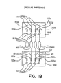
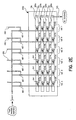
- FIG. 1A through 1C are schematic views of four-channel parallel flow reactor adapted for flow partitioning (Fig. 1A), pressure partitioning (Fig. 1B) or both flow-partitioning and pressure partitioning (Fig. 1C).
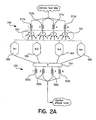
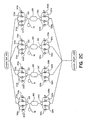
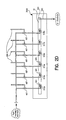
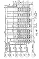
- FIG. 2A through 2F are schematic views of variously configured flow-distribution schemes for a four-channel parallel flow reactor.
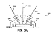
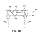
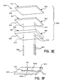
- FIG. 3A through 3I are schematic views (Fig. 3A, 3B, 3C, 3D), exploded perspective views (Fig. 3E, 3G, 31) and perspective view (Fig. 3F), of one or more microchip bodies mounted on a substrate (Fig. 3A, 3B, 3C, 3D, 3I) and of an exemplary single-channel legislation.
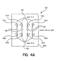
- FIG. 4A through 4F are schematic views of variously configured flow-distribution schemes for a four-channel parallel flow reactor.
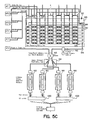
- FIG. 5A through 5C are schematic views showing various alternative embodiments for integrated multi-channel parallel reactors having one or more of a flow-partitioning subsystem, a pressure-partitioning subsystem or a feed-composition subsystem.
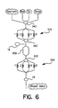
- FIG. 6 is a schematic view illustrating an integrated chemical processing system for pretreatment and reaction of catalysts (or catalyst precursors) in - situ in the reaction cavity, prior to the reaction of interest.
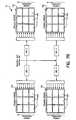
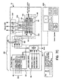
- FIG. 7A through 7C are schematic views illustrating an integrated chemical reaction system that includes multi-channel parallel flow reactors.
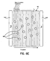
- FIG. 8A through 8E are schematic views illustrating various preferred configurations for a parallel flow reactor having four or more channels (Fig. 8A, 8B, 8D), single-channel reactor detail (Fig. 8C) and a temperature-control strategy (Fig. 8E).
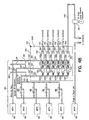
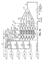
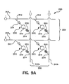
- FIG. 9A and 9B are schematic views showing an array of microvalves and actuation system (Fig. 9A) and associated valve logic (Fig. 9B).
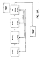
- FIG. 10A and 10B are schematic views showing, for example, how a lead composition can be evaluated in a process optimization reactor with respect to optimization of synthesis protocols, processing / treatment (e.g. ,reduction) conditions, and/or reaction conditions. Data reduction from one or more of such optimization efforts can then be integrated as feedback into further investigations with the process, preferably moderated with economic evaluations based, for example, on economic models.
- Preferred variables in connection with each of the synthesis optimization, processing optimization, reaction optimization, reactor optimization, and catalyst optimization are summarized in Figure 10B.
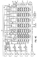
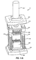
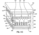
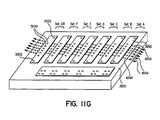
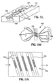
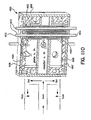
- Fig. 11A through 11 O are perspective views (Fig. 11A, 11C, 11G, 11J, 11L,), schematic views (Fig. 11B, 11M) top plan views (Fig. 11D, 11E, 11F, 11N,), cross-sectional views (11H, 11I, 11K, 11O) showing various aspects of a twenty-four channel parallel flow reactor having variable feed composition (Fig. 11A, 11B), including specifically a distribution module (Fig. 11C), a microchip body with integral set of flow restrictors (Fig. 11D, 11E, 11F), a flow restrictor block (Fig. 11G), a microvalve (Fig. 11H, 11I), a split restrictor/mass-flow-sensor block (Fig. 11J, 11K), a mass flow sensor (Fig. 11L, 11M, 11N) and a reactor module (Fig. 11O).
- a distribution module Fig. 11C
- a microchip body with integral set of flow restrictors Fig. 11D, 11E, 11F
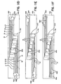
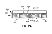
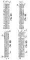
- Fig. 12A through 12F are schematic, cross-sectional views showing various stages of one microfabrication approach for forming a microfabricated set of flow restrictors integral with a substrate or with a microchip body.
- a chemical processing system is a reaction system that comprises a plurality of reactors, a fluid distribution system, and optionally, a detection system.
- the fluid distribution system comprises an inlet subsystem for providing reactants to the reactors, and an outlet subsystem for discharging effluents from the reactors.
- a feed-composition subsystem ⁇ for providing different feed compositions to the reactors can be included in the inlet subsystem.
- a flow-partitioning subsystem ⁇ for providing different flow rates to the reactors, and/or a pressure-partitioning subsystems ⁇ for providing different pressures in the reactors can be included as part of the inlet subsystem and/or in the outlet subsystem.
- a temperature control subsystem can also be included in the reaction system, for control of reaction temperature and feed temperature.
- the detection system can be a separate, stand-alone system, or can be integral with the reaction system.
- one or more reactants are fed from an external reactant source 20 through the external distribution system 480 and the internal distribution system 500 to an array 100 of reactors 600.
- Feed compositions are varied for two or more, preferably four or more of the reaction feed channels, preferably as part of
- the varied feed-compositions can be sent to dedicated reactors 600, or can be split into two or more streams to serve two or more reactors 600.
- the varied feed compositions can be sent to the reactors 600 directly, or through a flow-partitioning and/or pressure-partitioning subsystems, for obtaining different flow rates and/or pressures ( e . g ., through inlet and outlet flow restrictors 510, 520).
- the reaction conditions are controlled to effect the chemical reaction of interest, and reactor effluents are simultaneously discharged through the outlet distribution system 501, to an external effluent sink 60 (e.g. to an external environment, controlled or not controlled, including for example to the atmosphere, to a hooded vent, to a pressure-controlled region, etc.).
- a detection system 1000 can be used to sample the reactor effluent.
- a preferred plurality of reactors can include an array 100 of reactors 600.
- the array 100 of reactors 600 can be formed in a common substrate, and the common substrate can include a plurality of laminae.
- the array 100 of reactors 600 can alternatively be formed in a plurality of separate modules, with each module comprising two or more, and preferably four or more reactors.
- the modules can each include at least one common substrate, and such substrates can include a plurality of laminae.
- the plurality of reactors is an array 100 of nine reactors 600 arranged in a 3 reactor by 3 reactor (3x3) configuration.
- the flow distribution system can comprise an inlet distribution subsystem 500 for providing fluid communication between an external distribution system 480 (including one or more external reactants sources 20 or treatment agent sources) and the plurality of reactors 600.
- the flow distribution system further comprises an outlet distribution subsystem 501 for providing fluid communication between the plurality of reactors 600 and one or more external effluent sinks 60 (or treatment agent sinks), optionally via a detection system 1000.
- the flow distribution system can comprise one or more of a flow
- partitioning subsystem a pressure partitioning subsystem, and/or a feed-composition subsystem.
- the inlet and outlet distribution subsystems 500, 501 comprise a first inlet set 510 of flow restrictors and a second outlet set 520 of flow restrictors such
- the total resistance R total between each of the channels of the reactor system and the ratio of resistances, R inlet : R outlet , between each of the channels are selected, configured or selectively configured to provide for varied flowrates (flow partitioning), varied pressure (pressure partitioning) or both varied flowrates and varied pressure (flow / pressure partitioning) between the flow channels for the plurality of reactors 600, each as generally described above.
- the flow and/or pressure can vary in any manner, including as a flow gradient or as a pressure gradient across the various reactors.
- the inlet distribution system 500 can also include a set of feed-component flow restrictors.
- the feed-component flow restrictors can be the same flow restrictors used as for flow- and/or pressure-partitioning (e.g. first set of inlet flow restrictors 510), or alternatively, the feed-composition flow-restrictors can be a separate, independent set of flow restrictors.
- the feed-composition subsystem can be part of the external distribution system 480 of the reaction system.
- the inlet flow restrictors, outlet flow restrictors and/or feed-composition flow restrictors are a portion of a fluid distribution path that provides a resistance to flow, and typically, provides a greater resistance to flow than the immediately upstream portion of the fluid distribution path of the chemical processing system.
- the flow restrictors can provide a resistance to flow between a reactant source and the reactors, or between the reactors and an effluent sink.
- the flow restrictors can provid a resistance to flow between a feed component source and a mixing zone (e.g. , mixing cavity, combined channel, reaction cavity, etc. ).
- Preferred flow restrictors include passive flow restrictors such as capillaries, microcapillaries, small channels, channels having orifices, and microfluidic channels ( e . g ., including microfabricated channels), among others.
- the flow restrictors are microfluidic channels, typically formed using microfabrication techniques, and can be integral with a substrate or with one or more microchip bodies mounted - fixedly or detachably - on a substrate.
- a further description of preferred flow restrictors is provided below, as well as in the co-pending patent application of Guari et al . (now U.S. Patent No. 6,149,882).
- flow control is preferably effected with flow restrictors, in some embodiments of the invention, it is contemplated that active flow-control elements can be used to control flow.
- active flow-control elements can be advantageously effected, for example, in reaction system embodiments in which the active flow-control elements are microfabricated or are integral with a substrate or with one or more microbodies mounted on the substrate.
- the fluid distribution system comprises a first set of four or more inlet flow restrictors, where each of the four or more inlet flow restrictors provides fluid communication between at least one reactant source and one of the four or more reactors.
- the reactant source can be an external reactant source, or an internal reactant source ( e . g . coming from a plurality of mixing zones of the feed-composition subsystem).
- the fluid distribution system preferably further comprises a second set of four or more outlet flow restrictors, each of the four or more outlet flow restrictors providing fluid communication between one or more of the four or more reactors and at least one external effluent sink.
- the sets of inlet and/or outlet flow restrictors can effect both flow- and pressure-partitioning; alternatively, these could be effected using separate sets of inlet and/or outlet flow restrictors.
- the invention can generally comprise a four- (or more-) channel flow reactor, ( e . g . microreactor), where each channel comprises at least one inlet flow restrictor, a reactor, and at least one outlet flow restrictor.
- the flow resistance of the first set of inlet flow restrictors ⁇ and additionally, or alternatively ⁇ the flow resistance of the second set of outlet flow restrictors, varies between each of the four or more channels.
- the total flow resistance for each of the channels, R total defined as the surn of the resistances of the inlet flow restrictor(s) and outlet flow restrictor(s), R inlet + R outlet , can be substantially the same between channels or can vary between channels, depending on the desired flow and pressure characteristics.
- the relative ratio of the resistances of the inlet flow restrictors to the resistances of the outlet flow restrictors, R inlet : R outlet can be substantially the same between channels or can vary between channels, depending on the desired flow and pressure characteristics.
- the chemical reaction system of the invention comprises the four or more reactors and a fluid distribution system that provides for a different flow-rate to each of the four or more reactors, while maintaining substantially the same pressure in each of the four or more reactors.
- the volume of the reaction cavity of the four or more reactors can be substantially the same or different, but is preferably the same, such that the residence times for reactants is related to the flowrates independently of reactor volume, and likewise varies. In some embodiments, however, the volume of the reaction cavity can be varied between different reactors, such that contact time can be varied in consideration of both varying flow rates and/or varying reaction cavity volumes.
- the fluid distribution system comprises a first set of inlet flow restrictors and a second set of outlet flow restrictors such that the total resistance R total varies between each of the four or more channels of the reactor system (thereby providing for different flowrates through each of the four or more channels), and such that the ratio of resistances, R inlet : R outlet , is substantially the same pressure between each of the four or more channels (thereby providing for substantially the same pressure in each of the four or more reactors).
- This "flow-partitioning / constant pressure" embodiment is exemplified and discussed in connection with Figure 1A, below.
- the chemical reaction system of the invention comprises the four or more reactors and a fluid distribution system that provides for a different pressure in each of the four or more reactors, while maintaining substantially the same flow-rate to each of the four or more reactors.
- the volume of the reaction cavity of the four or more reactors can be substantially the same or different, but is preferably the same, such that the residence times for reactants is likewise substantially the same in each of the four or more reactors.
- the fluid distribution system can comprise a first set of inlet flow restrictors and a second set of outlet flow restrictors such that the total resistance R total is substantially the same between each of the four or more channels of the reactor system (thereby providing for substantially the same flowrates through each of the four or more channels), and such that the ratio of resistances, R inlet : R outlet , varies between each of the four or more channels (thereby providing for varying pressure in each of the four or more reactors).
- This "pressure partitioning / constant flow" embodiment is exemplified and discussed in connection with Figure 1B, below.
- the chemical reaction system of the invention comprises the four or more reactors and a fluid distribution system that provides for a different flow-rate to each of the four or more reactors, and additionally, a different pressure in each of the four or more reactors.
- the volume of the reaction cavity of the four or more reactors can be substantially the same or different, but is preferably the same, such that the residence times for reactants is related to the flowrates independently of reactor volume, and likewise varies.
- the fluid distribution system can comprise a first set of inlet flow restrictors and a second set of outlet flow restrictors such that the total resistance R total varies between each of the four or more channels of the reactor system (thereby providing for varying flowrates through each of the four or more channels), and such that the ratio of resistances, R inlet : R outlet , also varies between each of the four or more channels (thereby also providing for varying pressure in each of the four or more reactors).
- This "flow partitioning / pressure partitioning" embodiment is exemplified and discussed in connection with Figure 1C, below.
- the fluid distribution system of any of the aforementioned chemical reaction systems can, as applicable, include a first set of four or more inlet flow restrictors, and additionally, ⁇ a second set of four or more outlet flow restrictors where the respective resistances of the inlet and/or outlet flow restrictors varies for each of the four or more channels by a common factor (e.g., each of the resistances of the four or more inlet restrictors and/or outlet restrictors varies by a factor of 2, a factor of 3, or some other common factor.
- Flow restrictors within a set of first and/or second flow restrictors preferably vary by a factor of 2, and are herein alternatively referred to as ''binary-ratioed flow restrictors.”
- the first set 510 of flow restrictors comprises a plurality of inlet flow restrictors 512a, 512b, 512c, 512d, each of which provides fluid communication between an inlet port 511 (that is in fluid communication with an external fluid distribution system 480, directly or via a feed-composition subsystem) and an outlet port 513 (that is in fluid communication with one of the plurality of reactors 600).
- the resistance to flow of the inlet flow restrictors 512a, 512b, 512c, 512d can be varied as described above (shown in Figure 1A, for example, with relative resistance values of 2, 4, 6 and 8, respectively).
- the second set 520 of flow restrictors comprises a plurality of outlet flow restrictors 522a, 522b, 522c, 522d, each of which provides fluid communication between an inlet port 521 (that is in fluid communication with one of the plurality of reactors 600) and an outlet port 523 (that is in fluid communication with a detection system 1000, and ultimately with an external effluent sink 60).
- the resistance to flow of the outlet flow restrictors 522a, 522b, 522c, 522d can be varied as described (shown in Figure 1A, for example, with relative resistance values of 1, 2, 3 and 4, respectively).
- Figure 1A schematically represents a flow-partitioning subsystem that illustrates the aforementioned flow-partitioning / constant pressure embodiment.
- Figure 1B represents a pressure-partitioning subsystem that depicts the aforementioned flow-partitioning / constant pressure embodiment.
- Figure 1 C represents both flow-partitioning and pressure-partitioning subsystems that shows the aforementioned flow-partitioning / pressure-partitioning embodiment.
- the set of inlet flow restrictors 510 and the set of outlet flow restrictors 520 are illustrated as being provided as modular fluidic chips 3000, such that the inlet flow restrictors 510 and/or outlet flow restrictors 520 are integral with a substrate or with one or more microchip bodies mounted on a substrate, as discussed in further detail below.
- the fluid distribution system of any of the aforementioned chemical reaction systems can be configured in a number of ways to provide a first set of four or more inlet flow restrictors, optionally together with a second set of four or more outlet flow restrictors.
- the following embodiments are, therefore, to be considered exemplary and non-limiting.
- a valving configuration can be employed in combination with various flow-restrictor configurations to provide a particular embodiment of interest.
- the valving configuration can include one or more selection valves, for example, for providing controlled selection between a plurality of inlet flow restrictors and a particular reactor ⁇ and additionally, or alternatively ⁇ between one of the reactors and a plurality of outlet flow restrictors.
- Selection valves can also be used to provide selective fluid communication between a reactant source and two or more sets of flow restrictors ⁇ referred to herein as a series of selectable sets of flow restrictors.
- the selection valves can single-input / multiple-output selection valves, multiple-input / single-output selection valves and/or multiple-input / multiple-output selection valves, and can be dedicated, for example, to a particular flow restrictor and/or to a particular reactor.
- individual flow isolation valves, series of isolation valves, and/or arrays of isolation valves can be employed.
- pluralities of individual isolation valves can be adapted for common actuation, to simultaneously open or close to effect coordinated operation of various aspects of the fluid distribution system.
- an array of valves can be employed comprising individually actuated, or commonly actuated microvalves, such as, for example, the array described in connection with Figures 9A and 9B.
- a set of inlet flow restrictors 510 can be selectively coupled to four or more reactors 600 through four or more selection valves 543 ( e.g . single-input, multiple output selection valves as illustrated).
- the effluents from the four or more reactors 600 can be selectively discharged to the set of outlet flow restrictors 520 via selection valve 543 ( e.g. , illustrated as a multiple input-multiple output selection valve).
- the flow resistances 512a, 512b, 512c, 512d of the inlet set 510, and the flow resistances 522a, 522b, 522c, 522d of the outlet set 520 are binary ratioed flow resistances.
- a plurality of selectable dedicated inlet flow restrictors having different resistances can provide fluid communication between a feed inlet source and one of the four or more reactors. Additionally or alternatively, a plurality of selectable dedicated outlet flow restrictors having different resistances can likewise provide fluid communication between one of the four or more reactors and an effluent outlet sink. Selection valves can provide for automated and/or manual selection of the particularly desired restrictor for that particular reactor.
- Figure 2B represents a single-reaction-channel version of this embodiment, and shows a plurality of selectable dedicated inlet flow restrictors 512, 514, 515, 516 ⁇ each of which are dedicated for selectable connection to the single, particular reactor 600, through an inlet selection valve 543.
- a plurality of selectable dedicated outlet flow restrictors 522, 526, 527, 528 are each dedicated to the reactor 600, and provide selectable fluid communication to the effluent outlet through an outlet selection valve 543.
- a pressure sensor 18 is also shown.
- the flow resistances of the inlet set 510, and the outlet set 520 are binary-ratioed flow resistances.
- Figure 2C represents a multi-channel version of the configuration described in connection with Figure 2B.
- a first plurality of selectable dedicated inlet flow restrictors 512a, 514a, 515a, 516a (having different flow resistances relative to each other) provides selectable fluid communication between at least one reactant source and a first reactor 600 of the four or more reactors.
- Inlet selection valves 543 provide selection between the plurality of inlet flow restrictors associated with each reactor.
- a second plurality, third plurality and fourth plurality of selectable dedicated inlet flow restrictors provides selectable fluid communication between the reactant source and a second reactor, a third reactor and a fourth reactor, respectively.
- the set of four or more inlet flow restrictors in operation can be selected to include at least one flow restrictor from each of the first plurality, the second plurality, the third plurality and the fourth plurality of selectable dedicated inlet flow restrictors.
- individual valves e.g. pneumatically actuated valves
- selection valves for selection of a plurality of dedicated inlet flow restrictors and/or outlet flow restrictors.
- Figure 2D shows a single-channel configuration that is analogous to that shown in Figure 2B, but which employs a plurality of inlet isolation valves 487 rather than a selection valve, to select from among a plurality of dedicated selectable inlet flow restrictors 512a, 514a, 515a, 516a, 517a, 518a.
- the inlet isolation valves 487 can be actuated ( e . g . pneumatically actuated) using actuation lines 490.
- the plurality of inlet flow restrictors 512a, 514a, 515a, 516a, 517a, 518a is provided as a microfluidic chip 3000 having a dedicated channel 16 providing fluid communication between each of the inlet flow restrictors and at least one of the reactors (or more reactors, if down-stream flow-splitting is used, as discussed below) via interface 541, interface 555 and feed channel 545.
- a similar plurality of inlet flow restrictors can be provided for each of the four or more reactors.
- an array of inlet flow restrictors 512a,b,c,d, 514a,b,c,d, 515a,b,c,c, 516a,b,c,d, 517a,b,c,d, 518a,b,c,d - together with an array of corresponding inlet isolation valves 487 can provide for substantial operational flexibility with respect to selecting various combinations of flow restrictors.
- a similar plurality of selectable dedicated outlet flow restrictors (not shown) can likewise be provided (for example, in a manner analogous to that shown in Fig. 2D or 2F).
- a series of selectable sets of inlet flow restrictors and additionally or alternatively, selectable sets of outlet flow restrictors can be configured and selected. Generally, selection is made between two or more sets of flow restrictors.
- a first set inlet of flow restrictors can comprise first, second, third and fourth inlet flow restrictors that provide fluid communication between a reactant source and first, second, third and fourth reactors, respectively.
- Each of the first, second, third and fourth inlet flow restrictors of the first set have a different flow resistance relative to each other.
- a second set of inlet flow restrictors can likewise first, second, third and fourth inlet flow restrictors providing fluid communication between the reactant source and the first, second, third and fourth reactors, respectively.
- Each of the first, second, third and fourth inlet flow restrictors of the second set have a different flow resistance relative to each other.
- the flow resistance of at least one of the four or more inlet flow restrictors of the second set varies from the flow resistance of the corresponding inlet flow restrictor of the first set.
- the first set or the second set of inlet flow restrictors can be selected to provide fluid communication between the at least one reactant source and the four or more reactors.
- a similar configuration can be effected for the outlet side.
- the flow and/or pressure can be selectably and controllably varied using a series of selectable sets of inlet (as shown) or outlet (not shown) flow restrictors, indicated in Figure 2E as SET A, SET B, SET C, SET D, SET E and SET F.
- Each of the sets (A-F) of feed-component flow restrictors comprises a set of inlet flow restrictors ( e .
- Inlet isolation valves 487 can be automatically and remotely actuated ⁇ each individually ⁇ via feed-component-isolation-valve actuating lines 490. Selective actuation of the feed-component isolation valves for a particular set ( e . g ., SET A, SET B, SET C, etc .) provides for flow through the flow restrictors associated with that particular set and into the associated reactors. It can be appreciated this embodiment provides extreme operational flexibility and control over flow and pressure for each of the reaction channels.
- the added flexibilty of selectably switching between various sets of flow restrictors, such that, for example, each of the four or more reactors can be screened under each of the six sets of varied flow and pressure conditions is particularly advantageous.
- the relative values of the flow restrictors of each set e.g., SET A, SET B, SET C, etc .
- the relative values are "rotated" from one set to another set with respect to the associated reactor, such that in operation, one can selectably obtain the same six variations in feed and/or pressure through each of the six reactors, merely by selecting each of the sets ( i .
- the first or second sets 510, 520 of flow restrictors can be provided to the fluid distribution system as modular units, such as modular fluidic chips in which the flow restrictors are integral with a substrate or with one or more microchip bodies mounted on a substrate.
- Selection valves and/or isolation valves, together with other components e . g ., flow sensors, pressure sensors, etc.
- the particular configuration of the external fluid distribution system 480 is not critical, but can preferably comprise an active flow control element 483 (shown as a mass flow controller (MFC)) configured to be in series with the first set 510 of flow restrictors.
- MFC mass flow controller
- the use of two flow control elements in series is advantageous to effect control, and preferably also to measure, flow rate and pressure to each reactor 600.
- the first flow control element e.g ., MFC
- the second flow control element e.g ., first set of inlet flow restrictors 510) providing more specific or "fine” flow control for a subgroup of reactors 600 or for individual reactors 600.
- reaction system of the invention also includes embodiments in which the feed composition can be simultaneously varied in the four or more reactors for the systematic evaluation of the effect of feed composition on the particular reaction of interest.
- the chemical reaction system of the invention comprises the four or more reactors and a fluid distribution system for simultaneously varying the composition of reactor feed for the four or more reactors.
- a fluid distribution system for simultaneously varying the composition of reactor feed for the four or more reactors.
- For each of the four or more reactors at least two and preferably at least three feed components are simultaneously supplied from external sources thereof to a mixing zone.
- Each of the four or more mixing zones is in fluid communication with at least one of the four or more reactors ⁇ directly, or through flow partitioning and/or pressure partitioning subsystems of the fluid distribution system.
- the particular nature or configuration of the mixing zone is not critical, and generally, the mixing zone can be a mixing chamber ( e.g. , suitable for static mixing and/or active mixing), a fluid distribution channel, a fluid-distribution flow restrictor, a reaction cavity, etc .
- At least one of the feed components (e . g . a first feed component) is provided to each of the four or more mixing zones through a set of four or more feed-component flow restrictors having varying flow resistances, such that the relative amount of the at least one feed component is varied between each of the four or more reactors.
- the set of feed-component flow restrictors can be considered a third set of flow-restrictors, if the distributions system also comprises independent and separate first sets of inlet-flow restrictors an second sets of outlet flow restrictors, as described above in connection with flow- and/or pressure-partitioning).
- the particular nature of each feed component is not narrowly critical.
- each feed component can be a homogeneous or a heterogeneous fluid (e . g ., gas or liquid), and can comprise one or more different species (e . g ., molecular reactants, inert diluents, etc .).
- the set of four or more feed-component flow restrictors comprises two or more subsets of feed-component flow restrictors, with each subset corresponding to a particular feed component.
- a first feed component is provided to each of the four or more mixing zones through a first subset of four or more first-feed-component flow restrictors, with each of the four or more first-feed-component flow restrictors providing fluid communication between an external source for the first feed component and one of the four or more mixing zones.
- the flow resistance of at least two of the four or more first-feed-component flow restrictors varies relative to each other, and preferably, the flow resistance of each of the four or more first-feed-component flow restrictors varies relative to the resistance of the other such restrictors in the set.
- a second feed component can be provided to each of the four or more mixing zones directly, or through a second subset of second-feed-component flow restrictors.
- a third feed component can be provided to each of the four or more mixing zones directly, or through a third subset of third-feed-component flow restrictors.
- additional feed components can be provided to each of the four or more mixing zones directly, or through additional subsets of additional-feed-component flow restrictors.
- the resistances of the flow restrictors included in the second subset of second-feed-component flow restrictors, in the third subset of third-feed-component flow restrictors, and/or in the additional subsets of additional-feed-component flow restrictors can be substantially the same as the other restrictors within that subset, or can vary relative to the other restrictors within that subset.
- the external fluid distribution system 480 ⁇ and additionally or alternatively - the internal inlet distribution subsystem 500 can further comprise a feed-composition control system (not shown in Figure 7A).
- the feed-composition control system can be of any suitable design. In a preferred embodiment, however, the feed-composition control system can be provided as discussed above. Reference is made to Figures 4A through 4E, together with 5A through 5C, for example, as discussed below.
- a feed control subsystem 525 (included as part of the external fluid distribution system 480 or as part of an internal fluid distribution system 500) can comprise a set of four or more feed-component flow resistors that comprises a first subset 531 (a, b, c, d, considered collectively) and a second subset 533 (a, b, c, d, considered collectively) of feed-component flow restrictors corresponding to a first feed component and a second feed component, respectively.
- a first feed component is provided from a first-feed-component source 530 to each of four mixing zones 540 through a first subset 531 comprising four first-feed-component flow restrictors 531a, 531b, 531c and 531d.
- a second feed component is provided from a second-feed-component source 532 to each of the four mixing zones 540 through a second subset 533 of second-feed-component flow restrictors 533a, 533b, 533c and 533d.
- the flow resistance of each of the first-feed-component flow restrictors 531a, 531b, 531c and 531d varies relative to each other.
- each of the second-feed-component flow restrictors 533a, 533b, 533c and 533d can be substantially the same as each other, or can vary relative to each other.
- the relative flow resistances for the first feed-component flow restrictors 531 a, 531b, 531 c and 531 d and the second feed-component flow restrictors 533a, 533b, 533c and 533d are selected to vary across each set, and further, are selected such that the total sum of the flow resistances for the group of flow restrictors associated with a particular mixing zone ( e.g .
- a first group comprising feed-component flow restrictors 531a and 533a; a second group comprising feed-component flow restrictors 531b and 533b, etc .) are substantially the same, such that substantially the same flow rate can be achieved through each of the four mixing zones 540.
- the feed-component flow resistances are illustrated as being included in the flow distribution system as a microfluidic chip 3000.
- groups of flow restrictors relates to a collection of flow restrictors that comprises two or more flow restrictors providing fluid communication between two or more different feed sources (e.g ., a first feed source and a second feed source) and the same, one particular mixing zone or flow channel.
- feed sources e.g ., a first feed source and a second feed source
- the resistance values for the flow restrictors included in a first subset and a second subset of flow restrictors (as well as in a third subset or additional subsets of flow restrictors) can be designed or selected such the the relative proportions (e . g ., partial pressure of gaseous feed components) of the first component and the second component varies between each of the four or more mixing zones, but such that the total flow to, and through each mixing zone is substantially the same.
- varied amounts of the first component e.g.
- a first gaseous reactant could be sent to each of the mixing zones, together and simultaneously with complementarily-varied amounts of the second component (e.g ., an inert "make-up" gas), with the resistances of the first and second subsets of feed-component flow-restrictors set being designed or selected such that the total flow rate through each of the mixing zones is substantially the same, thereby providing for substantially equal feed with varied compositions.
- the second component e.g ., an inert "make-up" gas
- Figure 4B shows a feed control subsystem 525 formed, for example, as a modular fluidic chip 3000 as part, for example, of an internal fluid distribution system 500.
- the internal fluid distribution system 500 comprises feed control subsystem 525 and is interfaced with an external fluid distribution system 480 through a plurality of internal-external-interface ports 485.
- the feed control subsystem 525 of the internal fluid distribution system 500 can comprise a set of four or more feed-component flow resistors that comprises a first subset 531 (a, b, c, d, e, f considered collectively), a second subset 533 (a, b, c, d, e, f considered collectively) and a third subset 535 (a, b, c, d, e, f considered collectively) of feed-component flow restrictors corresponding to a first feed component, a second feed component and a third feed component, respectively.
- a first feed component is provided from a first-feed-component source 530 to each of six mixing zones 540 through a first subset 531 comprising six first-feed-component flow restrictors 531 a, 531b, 531 c, 531 d, 531 and 531f.
- a second feed component is provided through a second-feed-component source 532 to each of the six mixing zones 540 through a second subset 533 of second-feed-component flow restrictors 533a, 533b, 533c, 533d, 533e and 533f.
- a third feed component is provided through a third-feed-component source 534 to each of the six mixing zones 540 through a third subset 535 of third-feed-component flow restrictors 535a, 535b, 535c, 532d, 532e and 532f.
- the flow resistance of each of the first-feed-component flow restrictors 531a, 531b, 531 c, 531 d 531e and 531 f varies relative to each other.
- the flow resistance of each of the second-feed-component flow restrictors 533a, 533b, 533c, 533d, 533e and 533f can be substantially the same as each other, or can vary relative to each other.
- the flow resistance of each of the third-feed-component flow restrictors 535a, 535b, 535c, 535d, 535e and 535f can be substantially the same as each other, or can vary relative to each other.
- the various flow restrictors 531a-f, 533a-f, 535a-f can be formed ( e.g. , fabricated) in a first laminate, and the various mixing zones 540 formed ( e.g ., fabricated) in a second laminae.
- the feed component sources 530, 532, 534 can be formed ( e.g. , fabricated) in the first laminae, or alternatively, in a third laminae.
- Fluid communication between the various flow restrictors 531a-f, 533a-f, 535a-f, and the various mixing zones 540 can be effected through vertically-oriented inter-laminae-passages 541.
- the six (or more) mixing zones 540 can be in fluid communication with reactor feed channels 545 through a plurality of internal-internal interface ports 555 for internal feed channels 545 (or alternatively, through internal-external-interface ports 485 (not shown) for external feed channels 545).
- Each of the six feed channels 545 can be in fluid communication with one or more reactors (not shown).
- the external fluid distribution system 480 can comprise, for example, a plurality of flow-control elements such as a plurality of mass flow controllers 483 designated in the figures as MFC1, MFC2, MFC3, MFC4, MFC5 and MFC6.
- Each of the mass flow controllers 483 can be in fluid communication with a gas supply system 481 (Fig. 7C; not shown in Fig. 4B) or from a liquid supply system 482 (Fig. 7C; not shown in Fig. 4B) and can provide controlled flow of individual fluids ⁇ reactants, inert diluent fluids, inert purge gasses, etc .
- a valving arrangement comprising a plurality of source fluid feed valves 486 can provide for selective mixing of various individual fluids to form various mixtures as the feed component sources 530', 532', 534'.
- the first, second, and third feed components can be selectively fed or isolated from the composition-control subsystem 535 by operation of first, second and third feed-component-isolation valves 487, 488 and 489, respectively.
- the feed component isolation valves 487, 488, 489 can be automatically and remotely actuated ⁇ each individually (not shown), all collectively (not shown), or two collectively and one individually (as shown in Fig. 4B) ⁇ via feed-component-isolation-valve actuating lines 490.
- Pressure control can be effected for each of the channels as desired, and preferably using a high-temperature back-pressure controller 492 each of the channels (shown in Fig. 4B for only one of the six feed channels 545).
- the fluid distribution can also comprise (externally or internally) an overflow passage 542 in fluid communication with the first-feed component source 530' such that some portion of the first feed component is allowed to vent through vertically-oriented inter-laminae-passages 541, 541', for example, to waste, optionally through an overflow flow restrictor 544.
- the combined feed control subsystem 525 and external distribution system 480 provides substantial flexibility for variably controlling the feed composition provided to each of the four or more reactors of the chemical reaction system.
- the first feed component source 530 is provided as a feed component to be controllably varied between the six feed compositions (and as such, is labeled in Figure 4B as the variable partial pressure reactants ("Variable PP Reactants”)).
- Controlled variation thereof is provided by flowing the first feed component from source 530 to each of the six mixing zones 540 through the first subset 531 of first-feed-component flow restrictors 531a, 531b, 531c, 531d, 531e and 531 f, each of which has a resistance that varies relative to each other.
- the second feed component source 532 is provided as a feed component controlled to be of substantially constant proportion (e.g ., partial pressure for gaseous feed component) in the feed compositions (and as such, is labeled in Figure 4B as the constant partial pressure reactants ("Constant PP Reactants”)).
- Substantially the same proportion of the second feed component is provided to each of the mixing zones by flowing the second feed component from source 532 to each of the six mixing zones 540 through the second subset 533 of second-feed-component flow restrictors 533a, 533b, 533c, 533d, 533e and 533f, each of which has a flow resistance that is substantially the same relative to each other.
- the source fluid feed valves 486 can be controlled to selectively align particular source fluids from particular mass flow controllers 483 to either the first (variable partial pressure) feed component source 530 or the second (constant partial pressure) feed component source 532.
- the third feed component source 534 is provided as an inert make-up fluid (e . g ., make-up gas) feed component controlled to be complimentarily varied between the six feed compositions ⁇ by flowing the third feed component from its source 534 to each of the six mixing zones 540 through the third subset 535 of third-feed-component flow restrictors 535a, 535b, 535c, 535d, 535e and 535f, each of which has a flow resistance that varies relative to each other ⁇ such that the combined flow of the first and third feed components is substantially the same through each of the mixing zones 540.
- make-up fluid e . g ., make-up gas
- the mass flow controllers 483 (or other fluid flow-control device) provide balanced flowrates ( i . e ., substantially the same total flowrate) for the first and third feed components through the first and third feed component sources, 530, 534, respectively
- the third subset of third-feed-component flow restrictors is complementary to the first subset of corresponding first-feed-component flow restrictors where the sum of the group of the first-feed-component flow resistance and the third-feed-component flow resistance associated with a particular mixing zone (e.g ., the mixing zone associated with flow restrictors 531a and 535a) is substantially the same as compared to such sum for the other mixing zones.
- the relative values of the first feed-component flow restrictors 531a-f of the first ( e . g ., variable partial pressure) subset is not narrowly critical, and can be selected based on design choice of the operator.
- Various preferred sets of such relative flow-resistance values are shown in Table 1, together with the corresponding flow resistance values for the third ( e . g ., make-up gas) subset of third feed-component flow restrictors 535a-f.
- the flow distribution subsystem shown in Figure 4B can be operated without use of the third (make-up) feed component by selectively isolating the make-up feed component from the third component source 534 by shutting the corresponding third-feed-component isolation valve 489.
- such embodiments represents and integrated flow-partitioning subsystem and feed-composition control subsystem.
- such embodiment can also comprise an integrated pressure-partitioning subsystem.
- such embodiment also provides for controlled variation of contact time and space velocity through the four or more reactors.
- the flow distribution subsystem shown in Figure 4B can be operated without use of the first (variable partial pressure) feed component by selectively isolating the make-up feed component from the first component source 530 by shutting the corresponding first-feed-component isolation valve 487.
- a number of other operational embodiments in the flow distribution subsystem shown in Figure 4B can also be effected, with specific embodiments being selected according to the desired variation or substantial equivalence of feed composition, flowrates (and relatedly, contact time and/or space velocity), and/or pressure. Selection of an appropriate and/or desired operation embodiment is, in view of the guidance provided herein, within the skill in the art.
- the subsystem can be operated without use of the second (constant partial pressure) feed component by selectively isolating the make-up feed component from the second component source 532 by shutting the corresponding first-feed-component isolation valve 488.
- the mass flow controllers 483 can be operated to effect unbalanced flow (i . e ., unequal total flow) as compared between the first, second and third feed-component sources 530, 532, 534.
- the feed composition portion of the fluid distribution system can be configured in a number of ways to provide a set of feed-composition flow restrictors for variably controlling the composition of components supplied to the four or more mixing zones.
- the following embodiments are, therefore, to be considered exemplary and non-limiting, even though particularly described herein.
- the feed composition subsystem ( e . g , portion) of the distribution system can be configured to provide a plurality of selectable dedicated groups of feed-composition flow restrictors, each of the feed-composition flow restrictor groups comprising two or more feed-component flow restrictors, and each of the feed-composition flow restrictor groups providing fluid communication between two or more external sources of feed components and a common mixing zone.
- the resistance of the flow restrictors within a particular dedicated group of feed-composition flow restrictors can be the same or can vary relative to each other.
- the resistance of the flow restrictors between different selectable dedicated groups of feed-composition flow restrictors preferably vary relative to each other with respect to the restrictors providing fluid communication with at least one of the feed components, such that each of the plurality of groups provides different ratios of feed components to the mixing zones relative to other groups within the plurality.
- Selection of the dedicated feed-composition flow restrictor groups can be effected downstream of the plurality of feed-composition flow restrictor groups ⁇ for example with a selection valve (Fig. 4C), or alternatively, upstream of the plurality of feed-composition flow restrictor groups ⁇ for example with a series of individual valves (Fig. 4D).
- the feed composition subsystem 525 of the distribution system 500 can be configured to provide a plurality of selectable dedicated groups of feed-composition flow restrictors ( e . g , a first group comprising flow restrictors 531a, 533a, 535a; , a second group comprising flow restrictors 531b, 533b, 535b; , a third group comprising flow restrictors 531c, 533c, 535c, etc .).
- Each of the plurality of feed-composition-flow-restrictor groups (e.g., group a) provides fluid communication between a feed component sources (e.g ., 530, 532, 533) and a common mixing zone 540.
- the resistance of the flow restrictors within a particular dedicated group of feed-composition flow restrictors e.g , 531a, 533a, 535a
- the resistance of the flow restrictors between different selectable dedicated groups of feed-composition flow restrictors e.
- group "a” (531a, 533a, 535a) versus group "b" (531b, 533b, 535b)) preferably vary relative to each other with respect to the restrictors providing fluid communication with at least one of the feed components (e.g . 531 a versus 531b), such that each of the plurality of groups provides different ratios of feed components to the mixing zones 540 relative to other groups within the plurality.
- Selection of the dedicated feed-composition flow restrictor groups can be effected downstream of the plurality of feed-composition flow restrictor groups ⁇ for example with a selection valve 543 (Fig.
- the feed-composition subsystem of the fluid distribution system can be configured to be selectably and controllably varied for each of two or more, preferably four or more mixing zones.
- a plurality of selectable dedicated feed-composition flow restrictor groups can provide selectable fluid communication between two or more external feed component sources and the mixing zone for each of the four or more channels of the reaction system, such that a set of feed-component flow restrictors can be selected from among such particularly dedicated selectable flow restrictor groups.
- An exemplary configuration (not shown) could employ a plurality of dedicated selectable feed-composition flow restrictor groups ( e .
- the feed-composition subsystem of the fluid distribution system comprises a series of selectable sets of feed-component flow restrictors.
- the series comprises two or more, preferably three or more, more preferably four or more sets of feed-component flow restrictors.
- Each of the two or more sets of feed-component flow restrictors comprises a first subset of four or more first-feed-component flow restrictors; each of the four or more first-feed-component flow restrictors providing fluid communication between an external source for the first feed component and one of the four or more mixing zones.
- the flow resistance of at least two of the four or more first-feed-component flow restrictors varies relative to each other. More preferably, the flow resistance of each of the four or more first-feed-component flow restrictors varies relative to the resistance of the other such restrictors in the set.
- Each of the two or more sets of feed-component flow restrictors can (optionally, but preferably) further comprise a second subset of four or more second-feed-component flow restrictors, each of the four or more second-feed-component flow restrictors providing fluid communication between an external source for the second feed component and one of the four or more mixing zones.
- the flow resistance of the four or more second-feed-component flow restrictors can vary or be substantially the same relative to each other.
- each of the two or more sets of feed-component flow restrictors further comprises a third subset of four or more third-feed-component flow restrictors, each of the four or more third-feed-component flow restrictors providing fluid communication between an external source for the third feed component and one of the four or more mixing zones.
- the flow resistance of the four or more third-feed-component flow restrictors can vary or be substantially the same relative to each other.
- This especially preferred feed-composition subsystem of the fluid distribution system can further comprise one or more valves for selecting between the two or more sets of feed-component flow restrictors. The particular nature of the valve or valves is not critical.
- valves can, for example, be rotary-type selection valves, a series of separate and individual valves, each valve being actuated individually, in groups or collectively, or alternatively an array of valves as described herein in connection with Figures 9A and 9B.
- a specific embodiment exemplifying this embodiment of the invention is shown in Figure 4E and discussed further below in connection therewith.
- the feed composition provided to each of the four or more reactors of the chemical reaction system can be selectably and controllably varied.
- the feed-composition subsystem 525 of the fluid distribution system 500 comprises a series of selectable (third) sets of feed-component flow restrictors, indicated in Figure 4E as SET A, SET B, SET C, SET D, SET E and SET F.
- Each of the sets (A-F) of feed-component flow restrictors comprises a first subset of first-feed-component flow restrictors ( e .
- the feed-control subsystem 525 can further comprise a second subset of second feed-component flow restrictors 533a-f, substantially as described in connection with Figure 4B above.
- This especially preferred feed-composition subsystem 525 of the fluid distribution system 500 can further comprise first, second and third feed-component-isolation valves 487, 488 and 489, respectively that can be automatically and remotely actuated ⁇ each individually (not shown), all collectively (not shown), and preferably one valve 488 individually and sets of the two feed component isolation valves 487 and 489 collectively with respect to each set (as shown in Fig. 4B) ⁇ via feed-component-isolation-valve actuating lines 490.
- Selective actuation of the feed-component isolation valves for the first and third feed-component sources 530, 534 associated with a particular set provides for the first and third feed components to flow through the flow restrictors associated with that particular set and into the mixing zones 540.
- Other components shown in Figure 4E are substantially as described in connection with Figure 4B. It can be appreciated this embodiment provides extreme operational flexibility and control over feed compositions to go to each of the four or more particular feed channels 545.
- the relative values of the first feed-component flow restrictors 531a-f of the first (e.g. , variable partial pressure) subset and/or the values of the second feed-component flow restrictors of third (e.g. , make-up gas) subset employed in connection with each set ( e.g. , SET A, SET B, SET C, etc.) is not narrowly critical, and can be selected based on design choice of the operator.
- the relative values are "rotated" from one set to another set with respect to the associated mixing zone 540 / feed channel 545, such that in operation, one can selectably obtain the same six variations in feed composition through each of the six mixing zones / feed channels 545, merely by selecting each of the sets ( i . e ., SET A through SET F) in turn.
- Various preferred sets of such "rotating" relative flow-resistance values are shown in Tables 2A through 2C based on linearly-varying values (Table 2A), symetrically-varying values (Table 2B) or binary-ratioed-varying values (Table 2C) or summing-resistance values (Table 2D).
- each of the flow restrictors included within an array of flow restrictors ⁇ such as, for example, an array of flow restrictors comprising a series of sets ( e . g ., SET A, SET B, SET C, etc .) of (third) feed-component flow restrictors, as described above, can be variably and controllably individually selected by fluidically coupling the array of flow restrictors with an array of valves.
- the array of valves can be a microvalve array 2500 that comprises an array of microvalves 2510 (not shown schematically) in operational communication with an array of microvalve actuators 2515 substantially as described in connection with Figures 9A and 9B.
- FIG. 4F Other components shown in Figure 4F are substantially as described in connection with Figure 4B or 4E. It can be appreciated this embodiment also provides extreme operational flexibility and control over feed compositions to go to each of the four or more particular feed channels 545. Operational aspects such as those discussed in connection with Figure 4B are applicable as well with respect to the embodiment shown in Figure 4E, with the added flexibilty of selectably switching between individual flow restrictors. As such, selection permutations can include, for example, both groups of flow restrictors providing feed components to a particular mixing zones 540, as well as sets of flow restrictors providing feed components in varied fashion between mixing zones 540.
- the various flow restrictors 531a-f, 533a-f, 535a-f can be formed ( e . g ., fabricated) in a first laminate, and the various mixing zones 540 formed ( e.g ., fabricated) in a second laminate situated, for example, under the first laminae.
- An array 2500 of selectable microvalves 2510 can be formed in a third laminae situated, for example, above the first laminate.
- the feed component sources 530, 532, 534 can be formed ( e.g ., fabricated) in a forth laminate, situated, for example, above the third laminae, such that a feed-component can flow through feed component sources 530, 532, 524, through selected valves 2510, through selected flow restrictors 231a-f, 233a-f, 235a-f associated with the selected valves 2510, to form various feed compositions within the mixing zones 540. Fluid communication between the various components of adjacent laminae ( e .
- Table 3 provides an exemplary, non-limiting relative flow-resistance values for an array comprising individually selectable flow restrictors shown in Figure 4F.
- a skilled artisan can, of course deviate from such values and remain within the scope of the invention.
- Sets of Resistance Values for Array of Individually Selectable Restrictors Relative Flow Resistance Flow Restrictors Set A Set B Set C Set D Set E Set F 531a : 535a 1 : 1 2 : 2 3 : 3 4 : 4 5 : 5 6 : 6 531b : 535b 1 : 1 2 : 2 3 : 3 4 : 4 5 : 5 6 : 6 531c : 535c 1 : 1 2 : 2 3 : 3 4 : 4 5 : 5 6 : 6 531d : 535d 1 : 1 2 : 2 3 : 3 4 : 4 5 : 5 6 : 6 531e : 535e 1 : 1 2 : 2 3 : 3 4
- feed components can be provided from an external source through a primary flow-control system prior to interfacing with the feed-composition subsystems of the invention.
- Primary flow control to or through each of the mixing zones is preferably effected, for example for gaseous fluids, using mass-flow controllers with back-pressure regulation (e . g ., using a high-temperature back-pressure controller).
- back-pressure regulation e . g ., using a high-temperature back-pressure controller
- pumps such as syringe pumps, HPLC pumps, etc. could be employed in combination with appropriate flow-sensing and flow-control systems.
- the pressure and/or total flow of the external sources for the first and second feed components can be varied relative to each other.
- the feed-composition subsystem can have the four or more mixing zones in fluid communication with one or more reactors, either directly, through one or more flow-splitters, through one or more selection valves, and additionally or alternatively through flow partitioning and/or pressure partitioning subsystems.
- a variable feed-composition subsystem of the fluid distribution system can comprise at least one set or subset of four or more feed-component flow restrictors, as described above, to provide first and preferably also second feed components to each of the four or more mixing zones such that four or more feed compositions (each varying relative to each other) are formed.
- each of the four or more mixing zones can be a dedicated mixing zone in fluid communication with only one of the four or more reactors. In other embodiments, however, each of the four or more mixing zones can be in fluid communication with a plurality of the four or more reactors, or alternatively, with each of the four or more reactors.
- a flow and/or pressure partitioning first inlet flow restrictors, and/or second outlet flow restrictors can provide fluid communication between the four or more mixing zones and the four or more reactors.
- the embodiments shown in Figures 5A and 5B are exemplary, and are discussed in greater detail below.
- a variable feed-composition subsystem of the fluid distribution system 500 can comprise at least one set or subset of four or more feed-component flow restrictors, as described above in connection with Figures 4A (for Fig.'s 5A and 5B) and in connection with Figure 4E (for Figure 5C).
- First and preferably also second feed components can be provided to each of the four or more mixing zones 540 such that four or more feed compositions (each varying relative to each other) are formed.
- each of the four or more mixing zones 540 can be a dedicated mixing zone in fluid communication with only one of the four or more reactors 600.
- each of the four or more mixing zones 540 can be in fluid communication with a plurality of the four or more reactors 600, or alternatively, with each of the four or more reactors.
- a flow and/or pressure partitioning first inlet flow restrictors, and/or second outlet flow restrictors can provide fluid communication between the four or more mixing zones 540 and the four or more reactors 600 (Fig.s 5A and 5B).
- the four or more mixing zones 540 can be in fluid communication with the reactors directly ⁇ without flow and/or pressure partitioning.
- Fig. 5C The array of reactors 600 as shown in Figure 5C can be substantially as shown and described in connection with Figure 8B, and can be in fluid communication with the four or more mixing zones 540 through one or more switching valves 493 and/or flow splitters 494.
- a feed-component flow resistance can also be, or can be considered as part of, the resistance for the inlet-flow restrictor for that reactor. See, for example, discussion provided in connection with Figures 4B and 4E, below.
- a set of four or more inlet flow restrictors, four or more outlet flow restrictors, and/or four or more feed-component flow restrictors (depending on the subsystem of interest), or a portion thereof, can be provided to the reactor system as a modular unit comprising one or more flow restrictors.
- the modular unit preferably comprises an essential absence of reactor components (e . g ., components having one or more surfaces that define the reaction cavity), but can in some embodiments, include such reactor components.
- the modular unit can, in either case, also include other components of the fluid distribution system or subsystems, including for example valves ( e . g ., selection valves, isolation valves) pressure sensors, flow sensors, interface connections, etc .).
- the modular unit can be a modular fluidic chip comprising a substrate and one or more flow restrictors integral therewith (e . g ., formed at least partially at, on or in the substrate).
- the substrate having integral flow restrictors can be the modular fluidic chip substrate itself, or alternatively, can be one or more microchip bodies mounted, fixedly or detachably, onto the microfluidic chip substrate ( i . e ., where the microfluid chip is a primary substrate, with secondary substrates comprising the flow restrictors being mounted thereon).
- both of such embodiments can be considered to be within the scope of the characterization of the flow restrictors as being integral with either a substrate or with one or more microchip bodies mounted on a substrate.
- the modular fluidic chip is preferably a plate-type substrate or block-type unit, and can comprise, for example, one or more substrates having one or more channels of controlled geometry operating as flow restrictors integral therewith or with one or more microchip bodies mounted thereon.
- the substrate or one more microchip bodies can comprise a plurality of laminae in which one or more flow restrictors are formed.
- Methods for producing such modular fluidic chip devices are generally known in various arts ( e . g ., circuit manufacturing), and are described below in connection with preferred embodiments of the invention.
- the modular fluidic chip can include other components, in addition to the one or more flow restrictors, including for example; microvalves ( e .
- isolation valves can be integral with a substrate or with one or more microchip bodies mounted on a substrate ⁇ either the same substrate / microchip bodies as the flow restrictors or different substrates / microchip bodies as the flow restrictors.
- Modular fluidic chips can be employed as a single modular fluidic chip (including, for example, a plurality of flow restrictors for use as described above in connection with a plurality of reactors), or alternatively as a plurality of modular fluidic chips.
- such modular fluid chips can be integrated with other, microscale reaction system components (e . g ., microreactors, microsensors, etc.), as described below and/or as described in, or varied from the co-pending application of Guan et al ., (now U.S. Patent No. 6,149,882).
- Such modular fluid chips can also be integrated with larger scale reaction system components.
- a modular unit can comprise a plurality of flow restrictors, preferably having varying resistances to flow, to serve as either a first or second set of inlet or outlet flow restrictors, respectively.
- the modular unit can comprise a series of two or more selectable sets of such flow restrictors.
- the modular unit can comprise a plurality of dedicated now-restrictors for a single particular reactor, from which a first or second set of flow restrictors can be selected ( e . g ., with a selection valve provided as part of the modular unit, or resident within the system).
- the modular unit can comprise a single flow restrictor dedicated for a single particular reactor, and set of such modular units can be used to form the set of first inlet or second outlet flow restrictors.
- feed-composition subsystems that provide for selectably and controllably varied feed compositions in multiple mixing zones / feed channels
- one or more of the following, or a portion thereof can be provided to the reactor system as a modular unit comprising: pluralities of selectable, dedicated feed-component flow restrictors, a set of four or more feed-component flow restrictors ( e.g ., with subsets, as described above), groups of feed-composition flow-restrictors, pluralities of feed-composition flow-restrictor groups, and/or a series of selectable sets of feed-component flow-restrictor groups.
- the modular unit comprises a plurality of flow restrictors, preferably having varying resistances to flow, to serve as a set of feed-component flow restrictors.
- the modular unit can comprise a plurality of selectable groups of feed-component flow-restrictors, each of the groups within the plurality being dedicated to a single particular mixing zone ( e.g ., feed channel), from which a set of flow restrictors can be selected ( e . g ., with appropriate valving, as described, provided as part of the modular unit, or otherwise resident within the system).
- the modular unit can comprise a single group of feed-composition flow restrictors for a single particular mixing zone ( e .
- the modular unit can comprise a series of two or more selectable (third) sets of feed-component flow restrictors, as described above.
- the modular unit preferably comprises an essential absence of reactor components (e.g ., components having one or more surfaces that define the reaction cavity), but can in some embodiment, include such reactor components.
- the particular design of the flow restrictors or sets of flow restrictors is not critical.
- the sets of flow restrictors can be fabricated as microfluidic channels having varying flow resistances connected between appropriate inlet and outlet plenums.
- pluralities of flow restrictors can be fabricated as microfluidic channels having substantially the same flow resistances connected between appropriate inlet and outlet plenums, with the outlet interfaces of such channels being cross-connected with other similarly fabricated pluralities, to form the sets of flow restrictors with varying resistances to flow.
- the shape and/or dimensions the channels are not limiting, except as specifically recited in the claims.
- the cross-sectional shape of a channel can be, for example, approximately square, rectangular, circular, oval, etc., or even irregular in shape, and may be determined primarily by the fabrication techniques employed. Approximately square or rectangular channels are typical, and the aspect ratio (width/depth) can be greater than 1, equal to 1 or less than 1. See, for example, U.S. Patent No. 5,842,787 to Kopf-Sill et al. Because, however, the shape and/or dimensions of the channel will affect the flow rate of reactants through each cavity ( e . g . reactor), these factors should be considered in connection with the overall chemical processing microsystem design.
- the channels can have dimensions, for an approximately square cross-section, of not more than about 1 cm x 1 cm, preferably of not more than about 5 mm x 5 nun, more preferably not more than about 2 mm x 2 mm, even more preferably of not more than about 1 mm x 1 mm, and still more preferably of not more than about 100 ⁇ m x 100 ⁇ m.
- Smaller dimensions can also be suitably employed in some applications, including dimensions of not more than about 10 ⁇ m x 10 ⁇ m, not more than about 1 ⁇ m x 1 ⁇ m, and not more than about 0.5 ⁇ m x 0.5 ⁇ m.
- the channel can have a rectangular cross-section with an aspect ratio of greater or less than one, and dimensions adjusted to as to provide the same general ranges of cross-sectional flow area as described for a square cross-sectional channel.
- the diameter can be not more than about 1 cm, preferably not more than about 5 mm, more preferably not more than about 2 mm, even more preferably not more than about 1 mm, and still more preferably not more than about 100 ⁇ m. Smaller dimensions can also be suitably employed in some applications, including a diameter of not more than about 10 ⁇ m, not more than about 1 ⁇ m, and not more than about 0.5 ⁇ m.
- the distribution channel can have a hydraulic radius of not more than about 2.5 mm, more preferably not more than about 1.25 mm, even more preferably of not more than about 0.5 mm, yet more preferably of not more than about 0.25 mm, and most preferably not more than about 25 ⁇ m.
- Smaller hydraulic radii can also be suitably employed in some applications, including a hydraulic radius of not more than about 2.5 ⁇ m, not more than about 0.25 ⁇ m, and not more than about 0.125 ⁇ m.
- the hydraulic radius of the distribution channel preferably ranges from about 2.5 mm to about 0.125 ⁇ m, more preferably from about 1.25 mm to about 0.25 ⁇ m, and most preferably from about 2 mm to about 2.5 ⁇ m.
- the shape and dimensions of the cross-section of the distribution channel can be constant along the entire length of a distribution path or, if desired, can be varied along such length. If shape and/or dimensions of the channel are varied along the fluid-distribution path, however, the symmetry is, in some applications, preferably maintained to provide for appropriate conductances along each flow-resistance channel.
- the length of the distribution path for example, between a common inlet or outlet plenum port and each terminal plenum is not generally limiting. In preferred embodiments, however, the length of each of the flow paths is designed such that the conductance is appropriate ( i . e ., substantially the same or purposefully varied, depending on the overall design scheme) for each of the flow paths.
- a modular fluidic chip can comprise a substrate 3600 comprising one or more flow passages comprising the flow restrictors (not shown).
- External fluid connectors 3642, 3643, 3644 can provide fluid communication with the flow passages on the substrate 3600.
- the fluid connectors can include first and second inlet fluid connectors 3642, 3643 providing fluid communication between first and second feed component sources, respectively, and a mixing zone, and can also include an outlet fluid connector 3644 providing fluid communication between the mixing zone and a downstream application ( e . g . a flow reactor, or a flow- and/or pressure-partitioning subsytem).
- Figures 3B, 3C and 3D show an alternative embodiment, in which the modular fluidic chip 3000 comprises one or more microchip bodies 3650 mounted on a substrate 3600.
- the substrate 3600 can include one or more fluidic passages 3515 providing fluid communication between the microchip bodies 3650 and external fluid connectors 3642, 3644, and/or between two or more microchip bodies 3650.
- Figure 3B could be representative of a flow- and/or pressure-partitioning subsystem, where a reactant source enters through inlet connector 3642 to a set of inlet flow restrictors (not shown) included in a microchip body 3650', through a passage 3515 to another microchip body 3650" that includes one or more microreactors (not shown), and is subsequently discharged through a passage 3515 and through a set of outlet flow restrictors (not shown) integral with a third microchip body 3650''', and then ultimately through outlet connector 3644.
- Figures 3C and 3D show alternative variations on the general concept.
- the substrate can generally be any body in which a flow restrictor (and/or other devices, such as valves, pressure detectors, mass flow sensors, etc ., as desired) can be integrally formed, or any body having a surface on which a flow restrictor (and/or other devices) can be mounted, directly ( e . g . by itself) or within another distinct body such as a microchip body.
- the substrate is preferably a substantially planar body having at least two substantially parallel opposing surfaces.
- the substrate can be a plate-type substrate such as a wafer.
- the substrate is preferably a machinable material, and most preferably a micromachinable material (i. e. , a material suitable for microfabrication techniques) ⁇ such as single crystal silicon.
- a micromachinable material i. e. , a material suitable for microfabrication techniques
- ⁇ such as single crystal silicon.
- suitable materials are known in the art for integral microfabrication of flow restrictors (e.g. gallium arsenide, quartz, ceramic, glass) silicon offers advantages of scale, availability, well-established fabrication foundries, expense and acceptable material properties. Some plastics can also be used for some applications.
- the substrate can advantageously comprise a plurality of laminae into which various components of the flow restrictors (and/or other devices) can be fabricated before assembly of the laminae to form the unified substrate.
- the substrate in which the array of four or more flow restrictors are mounted on the substrate - either fixedly mounted ( e.g. bonded) or detachably mounted ( e.g. with a releasable seal) ⁇ the substrate can be of any material consistent with the required mechanical strength, operational conditions ( e . g . temperature) and mounting approach. Materials having a relatively high thermal conductivity may be used in some applications, for example, to provide for efficient heat transfer and a large thermal mass.
- Copper, stainless steel or other metals are exemplary suitable materials for this embodiment, and may be coated with one or more other materials (e . g . nickel-coated copper) to provide additionally desired properties (e . g ., chemical inertness) in combination.
- Materials that are at least machinable (on a macro-scale) are likewise preferred, to provide for assembly and other features (e.g. thermocouples, etc., as described below.
- the substrate can have a mounting surface, and preferably an exposed mounting surface adapted to receive a corresponding mounting surface of the flow restrictors or of the microchip bodies comprising the flow restrictors.
- the substrate can further comprise other features.
- the substrate can comprise multiple passageways for providing fluid communication between the flow restrictors and components (or additional components) of the fluid distribution system that are external to the substrate (e.g. to the external reactant sources, or to exhaust ports or exhaust manifolds for discharging samples).
- the substrate can further comprise four or more pairs of passages formed in the substrate for fluid communication with the four or more flow restrictors, respectively.
- Each pair of passages can comprise a first inlet passage for fluid communication with the inlet port of one of the flow restrictors, and a second outlet passage for fluid communication with the outlet port of the one of the flow restrictors.
- the substrate can generally comprise additional components for system operational control, including for example: temperature-measuring devices (e.g ., thermocouples, RTD's); heating blocks in thermal communication with a heat source (e.g. , a fluid heat exchanger and/or resistive heating elements such as cartridge heaters); sensors ( e . g . pressure sensors, flow sensors); and/or one or more exhaust manifolds.
- the substrate preferably comprises a plurality of laminae into which into which various components of the flow restrictors can be microfabricated before assembly of the laminae to form the unified substrate.
- a set of flow restrictors e .
- inlet flow restrictors 510 can be integrally microfabricated with a substrate 3600 comprising a first central laminate 3610 (also referred to herein as a "flow-restrictor wafer"), a second bottom wafer 3620 (also referred to herein as a "capillary wafer”), and a third top wafer 3630 (also referred to herein as a "capping wafer”).
- first central laminate 3610 also referred to herein as a "flow-restrictor wafer”
- second bottom wafer 3620 also referred to herein as a "capillary wafer”
- a third top wafer 3630 also referred to herein as a "capping wafer”
- the first central laminate 3610 comprises a first surface 3611, a substantially parallel, opposing second surface 3612, and a pair of microchannels 3516 having different resistances to flow and formed in the first surface 3611.
- Inlet port 3512 and outlet port 3514 are situated at opposing ends of the microchannels 3516, and extend from the microchannels 3516 through the central laminate 3610 to the second surface 3612 thereof.
- the inlet and outlet ports 3512, 3514 are defined by interior cylindrical walls that extend substantially normal to the second surface 3612 of the central laminate 3610.
- the second bottom laminate 3620 comprises a first surface 3621, a substantially parallel, opposing second surface 3622, and apertures ⁇ specifically first aperture 3512' and a pair of second apertures 3514' in substantially alignment with the inlet and outlet ports 3512, 3514, respectively of the central laminate 3610.
- the first and second apertures 3512', 3514' are essentially an extension of the inlet port and outlet ports 3512, 3514, respectively, and define interior cylindrical walls that extend substantially normal to the exposed, exterior second surface 3622 of the bottom capillary laminate 3620.
- the third top laminate 3630 comprises a first surface 3631, and a substantially parallel, opposing second surface 3632.
- the first, second and third laminates 3610, 3620, 3630 can be bonded ⁇ with a high-temperature glue (e . g . epoxy or polyimide), via anodic bonding or via fusion bonding to form a unitary substrate 600 comprising the flow restrictors 3516.
- a high-temperature glue e . g . epoxy or polyimide
- anodic bonding or via fusion bonding to form a unitary substrate 600 comprising the flow restrictors 3516.
- the apertures 3512', 3514' of the bottom laminate 3620 are sized to correspond to the outside diameter of a pair of capillaries ⁇ specifically a first inlet capillary 3642 ( e . g . in fluid communication with a reactant source) and a pair of second outlet capillaries 3644 ( e . g ., in fluid communication with two or more reactors).
- the inlet capillary 3642 and outlet capillaries 3644 can each be bonded ( e . g .
- the bottom laminate 3620 serves to support, as well as align the external capillaries 3642, 3644 to the inlet and outlet ports 3612, 3614, respectively, of the flow-detector laminate 3610.
- the flow restrictors are preferably integrally formed in one or more microchip bodies, and the one or more microchip bodies are mounted on the substrate.
- a microchip body can comprise a single flow restrictor or a single set of four or more flow restrictors.
- individually-packaged flow restrictors or sets of flow restrictors provides greater flexibility with respect to selecting appropriate flow restrictors. For example, the performance characteristics (e.g ., conductance, leak testing) can be evaluated for each set of flow restrictors, and selection based on the results of the evaluation (e.g. , including only flow restrictors that satisfy performance specifications).
- a series of sets of flow restrictors or a plurality of groups of flow restrictors can be integral with a common microchip body.
- the microchip body can generally be any body in which a flow restrictor can be integrally formed, that is mountable on a substrate ⁇ either fixedly mounted or detachably mounted.
- the microchip body has at least one mounting surface for mounting on a substrate, the mounting surface being adapted for reception with a corresponding mounting surface of the substrate.
- the microchip body is preferably a substantially planar body having at least two substantially parallel opposing surfaces.
- the microchip body can be a plate-type substrate such as a wafer.
- the microchip body is preferably a micromachinable material ( i.e. , a material suitable for microfabrication techniques) ⁇ such as single crystal silicon.
- the microchip body material should generally be suitable for use under the conditions required in operation (e.g ., with respect to temperature, etc .).
- Other suitable materials known in the art for integral microfabrication of flow restrictors e.g. gallium arsenide, quartz, ceramic, glass
- Some plastics can also be used for some applications.
- the microchip body can advantageously comprise a plurality of laminae into which various components of the flow restrictors can be fabricated before assembly of the laminae to form the unified microchip body.
- the particular size of the microchip body is not narrowly critical, and will depend on design considerations and applications.
- microchip body including for example, the number of flow restrictors integrally formed in the microchip body, required spacing between flow restrictors (where the microchip body comprises two or more flow restrictors), etc ..
- g . can range in size from about 100 cm 2 to about 10 ⁇ m 2 , preferably from about 25 cm 2 to about 1 mm 2 , and more preferably from about 10 cm 2 to about 1 cm 2 surface area, and from about 1 cm to about 100 ⁇ m (thickness), preferably from about 7 mm to about 200 ⁇ m, and from about 5 mm to about 500 ⁇ m, with a most preferred thickness of about 1 mm or about 2 mm.
- Typical and preferred sizes of a microchip body of a plate-type configuration that is mounted on the substrate as a module comprising two or more flow restrictors can be the above-recited sizes multiplied by the number of flow restrictors, with accounting for the required spacing between flow restrictors or sets thereof.
- Preferred spatial densities of flow restrictors on the microchip body is not critical, and can be consistent with the requirements of the reactors (or other applications) with which the fluid distribution system will be used (i.e., whether integral with a substrate or with a microchip body).
- the microchip body can also include one or more other structural features in addition to the structural features of the flow restrictor.
- a flow restrictor integral with microchip body can include (in addition to one or more inlet ports, one or more outlet ports, and one or more microchannels) one or more integral temperature-measuring devices (e . g . thermocouples), active temperature-control devices ( e . g . fluid-type heat exhangers), passive temperature-control devices ( e . g . thermal insulating regions ⁇ such as between microdetctors), microfabricated valves, microfabricated pumps, microfabricated flow sensors, microfabricated pressure sensors, etc .
- the preferred microchip bodies of the invention consist essentially of one or more flow restrictors or sets of flow restrictors ⁇ and have an essential substantial absence of other active microcomponents (but can include passive microcomponents such as flow channels, capillaries, thermal insulating regions, etc).
- Such microchip bodies with integral flow restrictors advantageously allow for simplicity in design and fabrication, reduced manufacturing costs, greater modularity and associated operational flexibility.
- the substrate on which such microchip bodies can can advantageously provide, in addition to a mechanical support for the microchip body, other integrated functionality such as flow distribution, temperature control, process monitoring, etc. Specifically preferred features are discussed in connection with the general substrate discription (above) and in connection with preferred embodiments with microchip bodies (below).
- the microchip body can be mounted on the substrate - individually, or as one or more modules (with each module comprising two or more flow restrictors) ⁇ by any suitable method.
- the microchip body can be fixedly mounted by bonding an exposed mounting surface of the microchip body to an exposed mounting surface of the substrate.
- the bonding can be chemical bonding using adhesives or glues, preferably high-temperature adhesives or glues such as epoxies or polyimides.
- the bonding can be anodic bonding, diffusion bonding, or other bonding methods known in the art or later developed.
- the microchip body can be detachably mounted on the substrate.
- the microdetector array can further comprise one or more releasable films situated between the mounting surface of the substrate and the mounting surface of the microchip body.
- the releaseable film can advantageously be a releaseable seal, with dual functionality of providing releasability between the substrate and the microchip body, as well as providing a seal around component features providing fluid communication between the substrate and the microchip body ( e . g ., inlet and outlet flow paths in fluid communication therebetween).
- the releasable seal could include o-rings around flow conduits or one or more gaskets (substantially flat, typically flexible, sheets of sealing material).
- the releasable film can also provide other features, including for example, features affecting thermal conduction paths or electrical conduction paths, and as such, can be a releasable thermal insulator or a releasable electrical insulator.
- the microchip body can comprise one or more sets of flow restrictors, preferably microfabricated flow restrictors, and one or more microchip bodies can be mounted on the same common substrate.
- an array comprising individually mounted microchip bodies affords significant flexibility with respect to operational flexibility for the application of interest.
- the individually-mounted microchip bodies are detachably mounted (rather than fixedly mounted)
- the array offers the further advantage of flexibility with respect to replacement of single microchip bodies.
- the microchip body can, however, also be a module comprising two or more sets of flow restrictors, preferably microfabricated flow restrictors.
- the separate microchip bodies each comprising any configuration of flow restrictors, as discussed above, can be formed separately, but are preferably formed collectively on a common wafer using batch microfabrication, and subsequently divided, as necessary, into separate microchip bodies as is common in the microfabrication art for circuit board components and other microfabricated devices.
- the inventions described herein could be manufactured on a relatively large scale on a common wafer.
- a set of flow restrictors 510 can be integrally microfabricated with a microchip body 3650 comprising a first bottom laminate 3680 (also referred to herein as a "flow-restrictor wafer") and a second top wafer 3690 (also referred to herein as a "capping wafer").
- first bottom laminate 3680 also referred to herein as a "flow-restrictor wafer”
- second top wafer 3690 also referred to herein as a "capping wafer”
- relative orientations are described as drawn (i.e., top, central and bottom), these orientations are intended for illustration purposes only, and should not be read as limiting on the scope of the invention. In fact, the orientation between top and bottom could be reversed, without change in the principle thereof.
- the first bottom laminate 3680 comprises a first surface 3681, a substantially parallel, opposing second surface 3682, and a pair of microchannels 3516a, 3516b.
- Inlet port 3512 and a pair of outlet ports 3514 are situated at opposing ends of the microchannels 3516, and extend from the microchannels 3516 through the flow-restrictor laminate 3680 to the second surface 3682 thereof.
- the inlet and outlet ports 3512, 3514 are defined by interior cylindrical walls that extend substantially normal to the second surface 3682 of the bottom laminate 3680.
- the second top laminate 3690 comprises a first surface 3691, and a substantially parallel, opposing second surface 3692.
- the first and second laminates 3680, 3690 can be bonded (as described above) to form to form a unitary microchip body 3650 comprising the set of flow restrictors 510.
- a plurality of microchip bodies 3650 are individually, and detachably mounted on the substrate 3600, with each of the microchip bodies comprising one or more flow restrictors.
- Each of the microchip bodies 3650 are plate-type bodies having a substantially planar first surface 3651 and a substantially parallel, opposing substantially planar second surface 3652.
- a second mounting surface 3652 of each of the microchip bodies 3650 is in contact with a mounting surface formed as a recessed region 3604 in the exposed first surface 3601 of the substrate 3600.
- Alignment pins 3653 can help for positioning of the microchip bodies 3650 during mounting.
- the microchip bodies 3650 When assembled, the microchip bodies 3650 are releasably held in the mounting position by islands (not shown) formed in the bottom surface of the cover block (not shown) that can be situated over the top surface 3601 of the substrate 3600. As shown, the microchip bodies 3650 comprise fluid connection ports (e.g . outlet ports 3514) at an exposed top surface 3651 of the microchip bodies 3650. Fluidic connections to fluidic cavities (e . g ., reactors or mixing zones) can be advantageously effected with each of the microchip bodies 3650 in fluid communication through a fluid connection port ( e . g ., inlet port 3512, not shown) with first inlet passage 3643 in the substrate 3600.
- a fluid connection port e . g ., inlet port 3512, not shown
- the substrate comprises pluralities of such passages 3643, one for each of the flow restrictors on the microchip bodies 3650.
- the flow passages 3643 in the substrate 3600 can be individually sealed in fluid communication with the ports of the microchip bodies using individual o-rings (not shows) as a releasable seal.
- the o-rings are seated in recessed o-ring seats 3649 that are formed in the mounting surface 3604 of the substrate 3600.
- One or more gaskets could be used alternatively, instead of the o-ring seals.
- the passages 643 extends downward from the first mounting surface 3604 of the substrate 3600 to a second surface 3602 of the substrate.
- the second surface 3602 may be an irregular surface, with some portion interior to the bulk of the substrate 3600, to accommodate a fitting, such as a conventional fitting (e . g . Valveco fitting) that provides fluid communication between the inlet passage 3643 and a capillary (not shown, e . g ., stainless steel capillaries, 1/16").
- a fitting such as a conventional fitting (e . g . Valveco fitting) that provides fluid communication between the inlet passage 3643 and a capillary (not shown, e . g ., stainless steel capillaries, 1/16").
- the fabrication of the integral flow restrictors can be effected using typical microfluidic microfabrication techniques, preferably in silicon, including for example, techniques selected from the group of oxidation, making, etching, thin-film deposition, planarization and bonding.
- Process temperature (e . g ., reaction temperature) can be controllably varied in combination with the aforementioned approaches for controlling reactor feed compositions, reactant flow rates and reactor pressure.
- the chemical processing system 10 can also include a temperature control system (not shown) adapted to provide a temperature gradient or other desired temperature variation across the array 100 of reactors 600.
- the temperature control can be for a group of reactors or for individual reactors, as desired, and can generally be as described below, and also as described in the Guan et al . (U.S. Patent No. 6,149,882) application.
- a temperature gradient can be advantageously applied to one or more embodiments of reaction systems (or, other chemical processsing systems) where the number of reactors seeing different temperatures is substantially enhanced, by orientating an array of reactors in a slightly skewed manner relative to the orientation of the temperature-contours (lines of constant temperature).
- the embodiment shown and discussed in connection with Figures 8E is exemplary.
- Particularly preferred parallel flow reaction systems can include a reactor module that comprises four or more parallel flow reactors having separate and independent temperature control for each of the four or more reactors.
- Substantial thermal management challenges exist for such reactor modules in which the four or more flow reactors are close-packed ⁇ that is, in which the four or more reactors have a spatial density (taken along one or more cross-sections) of not less than about 1 reactor /100 cm 2 , preferably not less than about 1 reactor / 50 cm 2 , more preferably not less than about 1 reactor /10 cm 2 , and, in some applications, not less than about 1 reactor / cm 2 , not less than about 2 reactors / cm 2 , not less than about 1 reactor / mm 2 .
- independent temperature control for each of the four or more reactors is effected using separately-controlled heating elements (e . g . resistive heating elements such as coil heaters) around each of the four or more reactors, while thermal isolation between the four or more reactors is accomplished by fluid-based heat exchange with an external heat sink.
- the heat flux being applied to each of the reactors has an axial profile (taken along the length of the flow reactor, with the direction of flow) that can be varied (fixedly varied, or controllably varied) to compensate for variations in the heat-flux profile associated with the circulating heat-exchange fluid cooling the reactors, and to compensate for the varied locations of the four or more reactors relative to other reactors and to the external environment ( e .
- the temperature-control system disclosed in the aformentioned patent application can have applications for control of other types of reaction systems (e . g ., batch reactors, semi-continuous reactors) and/or in non-reaction chemical processing systems ( e . g . calcining of heterogeneous catalysts) where parallel, independent temperature control is desirable.
- reaction systems e . g ., batch reactors, semi-continuous reactors
- non-reaction chemical processing systems e . g . calcining of heterogeneous catalysts
- a plurality of arrays 100 of reactors 600 can be combined into a single, integrated chemical processing system 10 to provide for robust control of various reactor conditions of interest.
- the outlet distribution subsystem 501, detection system 1000 and effluent sinks of the embodiment shown in Figure 7A are not shown in Figure 7B.
- the chemical processing system 10 comprises four 9-channel (3x3) arrays 100 of reactors 600, together with four inlet distribution subsystems 500. Reactant feed streams are provided to each of the four inlet distribution subsystems 500 from a corresponding set of four dedicated active flow control elements 483 ( e . g ., MFC's).
- the external fluid distribution system 480 comprises gas and liquid reagent (or treatment agent) supply systems 481, 482, hot dash pot 484 and appropriate vents, drains, and connecting piping or conduits suitable for fluid communication between indicated components.
- the external fluid distribution system 480 ⁇ and additionally or alternatively ⁇ the internal inlet distribution subsystem 500 can further comprise a feed-composition control system (not shown in Figure 7C), including for example feed-composition control systems as described above in connection with Figures 4A through 4E, and especially Figure 4E.
- a feed-composition control system (not shown in Figure 7C), including for example feed-composition control systems as described above in connection with Figures 4A through 4E, and especially Figure 4E.
- Each of the chemical reaction systems and/or chemical processing system can further comprise a detection system 1000 (e . g ., parallel gas chromatograph).
- a detection system 1000 e . g ., parallel gas chromatograph
- a number of detection schemes suitable for high-throughput, multi-channel reaction systems are known in the art and can be employed in connection with the present invention.
- Exemplary general detection approaches include, without limitation, parallel, quasi-parallel (hybrid parallel-serial) or rapid serial approaches involving, for example, gas chromatography (GC), mass spectrometry (MS), infrared spectroscopy ( e .
- the detection system can include distribution valves and/or selection valves (not shown in Figure 7C) as described in the Guan et al . and the Bergh et al . applications, for multiplexed selective sampling.
- An array of addressable microvalves, discussed below in connection with Figures 9A and 9B, can also be advantageously employed in connection with the detection system 1000.
- a detection system especially preferred for use in connection with the reaction system of the present invention can comprise a multi-channel gas chromatograph. Reactor effluents discharged from each of the four or more reactors can be simultantously injected into such a multi-channel ( i . e . parallel) gas chromatograph using a parallel injection valve.
- the chemical processing system 10 further comprises a pressure-control manifold 1500 for variably controlling pressure in the reactors 600, comprising a plurality of pressure-control valves, each of which is in fluid communication with one or more of the reactors 600 and/or the effluent of the detection system 1000.
- the chemical processing system 10 can be controlled with a control system 2000 comprising one or more microprocessors, flow controllers, temperature controllers, pressure controllers, detection system controllers, power supply controllers, etc ..
- the four or more reactors can be of any suitable design, including for example designs modeling or substantially modeling continuous-stirred-tank reactors (CSTR's), fixed bed reactors, fluidized bed reactors, plug-flow reactors, channel-type reactors, etc .. Designs modeling or substantially modeling fixed bed, plug-flow and CSTR-type reactors are preferred.
- CSTR's continuous-stirred-tank reactors
- the aforementioned co-pending patent application of Guan et al . (filed June 9, 1998) include preferred reactor and reactor configuration designs.
- the reactor types in a particular chemical reaction system can be identical to each other, substantially the same as each other, or varied ( e . g ., for optimization of reactor-type) in a particular chemical reaction system.
- Each of the aforementioned chemical reaction systems is preferably a microsystem, in which the volume of the reaction cavity is not more than about 1 ml.
- the reaction cavities can have a volume of not more than about 100 ⁇ l, not more than about 10 ⁇ l, or not more than about 1 ⁇ l.
- the smaller volume reaction systems are particularly advantageous, for example, with respect to heat transfer characteristics, as well as handling and interchanging of modular components ( e . g ., arrays of diverse materials, flow-restrictor modules, reactor modules, etc .).
- the plurality of reactors are two or more reactors, preferably four or more reactors, and more preferably nine or more reactors. Higher numbers of reactors, including sixteen, twenty-four, forty-eight or ninety-six or more reactors are contemplated. When an array of microreactors is used in connection with the invention, the number of reactors can be hundreds or thousands.
- an integrated chemical reaction system 10 comprising a flow-through reactor design (e . g,, analogous to a plug-flow reactor) can comprise a plurality of microreactors 600 formed in one or more laminae 100.
- the material-containing laminate 100 comprises a candidate material 920 such as bulk catalyst (e . g ., as beads, pellets or particulates, etc .) or supported catalysts contained within the microreactors by a porous barrier 126 (e.g., frits, porous plug, etc., as described above).
- a porous barrier 126 e.g., frits, porous plug, etc., as described above.
- the plurality of microreactoxs 600 are sealed and heated by adjacent .
- Reactants 20 are provided to the microreactors 600 through an inlet distribution manifold 500 in fluid communication with the microreactors 600 via connecting channels 550.
- the distribution manifold can comprise a first set of inlet flow restrictors (not shown in Figure 8A), and optionally, a feed-composition varying subsystems (not shown in Figure 8A), as described above.
- the distribution manifold 500 is thermally isolated from the microreactors 600 by temperature control block 400.
- reactor effluent 60 is passed through connection channels 550 to a discharge manifold 501, and further to an external distribution (waste) system.
- the discharge manifold 501 can comprise a second set of outlet flow restrictors (not shown in Figure 8A).
- the discharge manifold 501 is likewise thermally insulated from the microreactors 600 by another temperature control block 400. Evaluation of the candidate materials can be determined by analysis of reaction products, for example, by sampling of the reactor effluent stream using one or more sampling probes 910 ( e .
- sampling needles that are in selective fluid communication with one or more of the microreactors 600, and in further fluid communication with a detection system (e . g ., gas chromatograph, mass spectrometer, FTIR, etc .).
- a septum or other suitable accessible barrier 911 may be employed in connection with the sampling system.
- a similar reaction system 10 is shown in Figure 8D, except that the outlet stream includes a "U-turn" to direct the effluent stream 60 to a discharge manifold 501 located in the vicinity of the inlet distribution mannifold 500.
- This design has some advantages with respect to flow control interfacing (localized area) and with respect to temperature control (single "cold zone").
- another integrated chemical reaction system 10 can comprise a tube-type flow-through reactor design ( e . g ,, analogous to a plug-flow reactor) ⁇ generally on a somewhat larger scale than the microreactor embodiment shown in Figure 8A.
- the reaction system 10 comprises a plurality of microreactors 600.
- Each of the reactors 600 can comprise, with reference to Figure 8C, an elongated reaction vessel 70 such as a tube or channel.
- the elongated reaction vessel 70 can be independent of other structure or can be integrated with and formed at, on or in a substrate ( e . g ., a plurality of laminae).
- the elongated reaction vessel 70 is preferably a stainless steel, ceramic, or quartz tube, and without limitation, preferably has a diameter ranging from about 1 mm to about 20 mm, more preferably from about 2 mm to about 10 mm, and most preferably from about 4 mm to about 8 mm.
- the elongated reaction vessel 70 can be lined with a liner 72 that is inert with respect to the reaction and reaction conditions being evaluated.
- the liner 72 can be, for example, a glass liner.
- a candidate material (e.g ., catalyst or catalyst precursor material) 74 can be provided to and situated in the elongated reaction vessel 70 in any suitable form ⁇ for catalysts as bulk catalyst or as supported catalysts ⁇ and in either case in various forms known in the art (e.g ., pellets, beads, particulates, microspheres, substantially uniform microspheres, etc ). Particle diameters are not narrowly critical, but can typically range from about 1 ⁇ m to about 1 mm, more typically from about 10 ⁇ m to about 500 ⁇ m, and even more typically from about 50 ⁇ m to about 250 ⁇ m.
- the candidate material 74 is preferably held in position between porous end caps 126 ( e .
- the reactors 600 can be fabricated using manual, semi-automated or automated instruments (e.g ., robotic handling instruments) to provide the candidate materials 74 and/or other components of the reactor 600.
- the reactors 600 shown in Figure 8B and 8C can have a low thermal mass, and can thereby provide for relatively fast thermal cycling for processing / treatment of the candidate materials (e.g .,for calcining of catalysts or catalyst precursors) and for establishing and/or varying reaction conditions in the reactors 600.
- the material-containing reactors 600 are formed as an array 100 of reactors 600, with each reactor 600 supported near the reactor inlet port 71 and the reactor outlet port 73 by a first and second support plates 954, 955.
- the plurality of reactors 600 are heated by temperature control blocks ⁇ shown as heaters 980 ⁇ adjacent to the material-containing portion of the reactors 600 and in thermal communication therewith.
- the center, material-containing region of the reaction system 10 can be a relatively "hot zone” region, while the inlet and outlet-containing regions can be relatively “cold zone” regions.
- the temperature can be varied between reaction vessels 600, and temperature variations ( e .
- g ., gradients can also, as desired, be established with multiple temperature zones along a single reactor 600 and/or along the material-containing portion of a single reactor 600.
- Seals, and preferably releasable seals between the fluid distribution system and the reactors 600 can be provided and integrated into the support plates 954, 955.
- Such a design allows for the fluid-distribution seals to be located in the cold zones ⁇ and outside of the hot-zone, thereby providing for greater flexibility with respect to sealing materials, etc.
- Exemplary sealing materials include graphite, fluoropolymer, metal seals, or other seal materials disclosed in the pending Guan et al . or Bergh et al . applications.
- Reactants 20 can be provided to the reactors 600 through an inlet distribution subsystem 500 in fluid communication with the microreactors 600.
- the inlet distribution subsystem 500 can comprise a first set 510 of inlet flow restrictors, and optionally, a feed-composition varying subsystems (not shown in Figure 8B), as described above.
- reactor effluents 60 are passed through an outlet (discharge) distribution subsystem 501, and further to an external distribution (waste) system.
- the outlet distribution subsystem 501 can comprise a second set 520 of outlet flow restrictors.
- the sets of inlet and outlet flow restrictors 510, 520 can, as shown in the emobiment of Figure 8B, be modular subunits such as modular fluidic chips dedicated to a group of four or more reactors 600, and as such, can be readily interchangeable to vary flow rates (and correspondingly, contact times) and/or pressure between various subgroups thereof and/or between various experimental runs.
- the inlet and outlet distribution subsystems 500, 501 can be thermally isolated from the microreactors 600 ( e .
- Evaluation of the candidate materials can be determined by analysis of reaction products, for example, by sampling of the reactor effluent streams as described above and/or in connection with the Guan et al . and Bergh et al . applications.
- the chemical reaction system can optionally be contained within an oven 750 (and in operation, a heated oven) ⁇ particularly when liquid reagents are employed ⁇ to provide for additional thermal energy to keep the feed stream and effluent streams in the vapor phase.
- a temperature gradient can be provided across an array 100 of reactors 600 by providing a heat source 1400 at T hot and a heat sink 1420.
- Lines of constant temperature, "temperature contours" are formed having varying temperatures T1, T2, T3, T4, .... Tn as shown.
- the difference in temperatures between the temperature contours can be substantially the same (as shown) or can vary.
- the array 100 of reactors 600 can be arranged and/or situated such that each of the four or more reactors 600 is at a different temperature (with the array skewed relative to the heat source / heat sink ⁇ or vice-versa).
- the array 100 can be arranged and/or situated such that a group of reactors 600 is at substantially the same temperature (not shown).
- Other variations, including radial temperature variations, with concentric temperature contours, can also be effected.
- a pneumatically active microvalve array 2500 can comprise a plurality, and preferably four or more microvalves (2510 ⁇ not shown schematically) in operational communication with four or more microvalve actuators 2515 arranged and/or formed at, on or in a common substrate.
- the microvalve actuators can actuate the microvalves.
- the common substrate can comprise a plurality of laminae, and the four or more microvalves and four or more microvalve actuators 2515 can be formed in the plurality of laminae.
- Each of the four or more microvalve actuators 2515 can be in selective fluid communication between a first pneumatic valve actuating line 2530a, 2530b of a first set 2530 of actuating lines, and a second pneumatic valve actuating line sample line 2550a, 2550b of a second set 2550 of actuating lines.
- the four or more microvalve actuators are in selective fluid communication between the sets of first and second valve actuating lines 2530 and lines 2550.
- each of the four or more actuating flowpaths comprises an actuator inlet 2512 in fluid communication with at least one of the first actuating lines 2530a, 2530b, and an actuator outlet 2514 in fluid communication with at least one of the second actuating lines 2550a, 2550b, and in selective fluid communication with the actuator inlet 2512.
- a valve control logic 2514 can provide for selective, controlled actuation of the microvalve actuator 2515 for operation of valve 2510.
- One or more flow restrictors 2516 can be provided in the actuator flowpath ( i.e ., between the actuator inlet 2512 and actuator outlet 2514), including for example as shown, between the microvalve actuator 2515 and the actuator outlet 2414.
- valve control logic 2514 can vary depending on the particular application, but can typically be an "AND” or an “OR” logic, such that valve control for four or more valves can be controlled using microprocessor based technology with appropriate software.
- the number of microvalve actuators and microvalves can be substantially larger, including numbers that are the same as the number of reactors as described, for example, in the Guan et al . (U.S. Patent No. 6,149,882) application. As applied to chemical processing systems having arrays of larger numbers of components ( e .
- the number of actuation circuits can be increased by log N (where N is the number of components) rather than being increased by N ⁇ which is the case with a heirarchy of individually-dedicated actuators.
- the array of microvalve actuators and microvalves can be fabricated by methods known in the art. See, for example: Rich et al ., " An 8-Bit Microflow Controller Using Pneumatically-Actuated Valves “, pp. 130-134, IEEE (1999); Wang et al ., " A Parylene Micro Check Valve ", pp.
- the array of microvalves and microvalve actuators can provide for selective sampling and multiplexing of a plurality and preferably four or more reactor effluent streams, and can be interfaced, for example, with detection instruments such as parallel GC and/or parallel MS; among others.
- microvalves 2500 can be integrated with flow distribution systems, such as those disclosed herein, as well as with those disclosed in the Guan et al ., and can be used with numerous other applications.
- the chemical processing systems of the invention can operate over various ranges of temperature, pressure, contact times and space velocities.
- the reactor temperature can generally range from about 0 °C to about 1000 °C, and preferably from about 20 °C to about 500 °C, and more preferably from about 100 °C to about 500 °C;
- the reactor pressure can range from about 1 bar to about 200 bar, and preferably from about 1 bar to about 10 bar;
- contact times can range from about 1 ⁇ sec to about 100 sec, preferably from about 1 ⁇ sec to about 10 seconds, and most preferably from about 0.2 seconds to about 5 seconds;
- space velocities can range from about 0.01 mL/ml hr to about 50 mL/ml hr, and preferably from about 0.1 mL/ml hr to about 3 mL/ml hr.
- explosive reactants e . g ., hydrocarbons and oxygen
- MVO reactors When employed in connection with a materials-science research program, MVO reactors can provide for high-throughput analysis and optimization of "lead" candidate materials developed with primary and/or secondary screening approaches.
- reaction systems of the present invention are particularly useful in , connection with high-throughput (i . e ., combinatorial) catalysis research programs.
- Preferred approaches are disclosed in U.S.Patent No. 6,149,882 to Guan et al .
- combinatorial (i . e ., high-throughput) research for heterogeneous catalysts such MVO reactors can be employed in a work-flow paradigm in which an identified "lead composition" is efficiently optimized and evaluated for potential commercial applications.
- a lead composition can be evaluated in an MVO reactor with respect to optimization of synthesis protocols, processing / treatment ( e .
- the invention is exemplified by a twenty-four channel, parallel-flow reaction system for effecting twenty-four simultaneous reactions.
- Each of the twenty-four reactors can be a fixed-bed type flow reactor, allowing for evaluation of candidate catalysts under varied process conditions.
- the twenty-four channel reactor includes a fluid distribution system having a feed-composition subsystem for simultaneously supplying six-different gaseous feed compositions ⁇ each feed composition comprising three feed components ⁇ to the reaction cavity of each of the twenty-four reactors.
- the reactor effluent is discharged from each reactor through the fluid distribution system to effluent and to a parallel gas chromatograph injection valve for simultaneous injection into a twenty-four channel parallel gas chromatrograph.
- the reactor can also include a temperature-control subsystem for controlling, individually, the temperature of each of the twenty-four reactors.
- the twenty-four channel reaction system 10 is a bench-top instrument comprising a distribution module 4500 and a reactor module 4600.
- the distribution module 4500 and reactor module 4600 are supported in a frame 4100 that includes a lower support shelf 4110, and upper support shelf 4130 and four guide posts 4120 (linear ball bearings).
- the distribution module 4500 can be operationally engaged with the reactor module 4600 by downward movement of a shaft 4142 connected at a lower end to the distribution module 4500 via a support block (not shown), and at an opposing upper end to a hydraulic jack 4140 (e.g. 100 kN, adjustable, regulated force) supported on a press frame 4145.
- a hydraulic jack 4140 e.g. 100 kN, adjustable, regulated force
- Preloaded springs 4146 are provided on each of the guide posts 4120 to ensure appropriate seating force between the reactor module 4600 and the lower support shelf 4110 to sequentially demount the distribution module from the reactor module (release of upper o-ring seals on reactor module), and subsequently, the reactor module lower o-rings).
- a gas-chromatograph-connector module 4200 provides twenty-four channel fluidic interface to a parallel gas chromatograph injection valve (not shown) situated under the lower support shelf 4110, and is in fluid communication with the reactor module 4600.
- the distribution module 4500 can be interfaced with an external fluid distribution system 480 having gas supply system 481 with associated mass flow controllers 483, and a liquid supply system 482 with associated evaporators 484, together with appropriate valving, substantially as described above.
- Three gaseous feed components are fed through external transfer lines 530' (variable partial pressure reactant feed source), 532' and (constant partial pressure reactant feed source), 534' (make-up gas) substantially as described in connection with Figure 4E to an internal inlet fluid distribution system 500 having an internal feed-composition subsystem 4525.
- Internal feed transfer lines 530, 534, and pairs of commonly-actuated inlet isolation valves 487, 489 provide selectable fluid communication to a series of six sets of flow restrictor groups ⁇ indicated as SET A, SET B, SET C, SET D, SET E, and SET F ⁇ with each set comprising six groups of flow restrictors.
- Each group of flow restrictors in a particular set include a first-feed-component flow restrictor in selectable fluid communication with the variable partial pressure feed source through transfer line 530 and inlet isolation valve 487, and a second-feed-component flow restrictor in fluid communication with the make-up feed source through transfer line 534 and inlet isolation valve 489.
- Internal feed transfer line 532 provides a constant partial pressure feed source through a set of six dedicated flow restrictors, where the flow restrictors have substantially the same resistance to flow ( i.e. , "constant resistance” flow restrictors, indicated as SET CR).
- the (varied) feed composition from the six groups of feed-component flow restrictors (after mixing feed components from the first-feed-component flow restrictors and second-feed-component flow restrictors in an internal mixing zone, not shown,) are fed through six respective discharge channels 4540.
- the combined feed composition (of the variable feed component / make-up feed component) are mixed with the constant feed component in the discharge channels 4540.
- a pressure sensor (illustrated as p1, p2, p3... etc .) monitors discharge channel 4540 pressure.
- Each of the resulting six varied feed composition feeds are discharged through an outlet isolation valve 4580, and then split four ways using flow-splitters to create twenty-four streams ⁇ with six groups of four steams each, and each group having a varied feed composition.
- Each of the twenty-four feed streams can be fed through a single, individual split restrictor 4570 ⁇ such as a capillary or as microfluidic channel ( e . g . having substantially the same resistance to flow as compared between reaction channels), and then through a mass flow sensor 4590 (MFS), before leaving the distribution module.
- MFS mass flow sensor 4590
- the distribution module 4500 is a separate, stand-alone subsystem that mounts in fluid communication with the reactor module 4600. Connector module 4200 and detection module 1000 are also shown.
- the distribution module 4500 was provided as a modular unit comprising a plurality of modular fluidic chips.
- the distribution module comprises a flow-restrictor block 4510 comprising a substrate 3600 having several microchip bodies (not shown) mounted thereon.
- the microchip bodies include flow restrictors (C1, C2, C3, etc .) from which sets of flow-restrictor groups are formed by fluidic connection.
- a series of commonly-actuated groups of microvalves can be precision machined and mounted as a valve block 4487 on one side of the distribution module 4500, or integrally therewith, including for example as a subblock integrally within the flow-restrictor block 4510 ⁇ for example, as indicated as 4587'with dotted lines.
- the groups of microvalves can be microfabricated and be integral with the flow restrictor blcok 4510 or with microchip bodies mounted on the flow-restrictor block 4510.
- the microvalves are pneumatically actuated with air supplied through control pressure ports 4512.
- Reactant sources including a variable partial pressure gas, a make-up gas and a constant partial pressure gas are supplied via external-internal inlet ports 4530, 4534, 4532, to provide fluid connection with internal transfer lines 530, 534, 532 , respectively (Fig. 11B).
- a cover 4504 and an insulator block 4502 are positioned over the flow-restrictor block 4510.
- the flow-restrictor block 4510 is situated over a heater block 4520 comprising resistive cartridge heaters 4522, pressure-sensor ports 4524 and thermocouple ports 4526.
- Capillary-type split restrictors (4570, Fig. 11B) extend between the heater block 4520 and the split-restrictor-mass flow sensor block 4550 ("SR-MFS block" 4550), that includes an array of microfabricated mass flow sensors 4590 downstream from each of the split restrictors, and connection ports 4552, 4553 for cooling fluid circulating through the SR-MFS block 4550.
- the feed passes from the mass flow sensors into reactor tubes (not shown) that extend upward from the reactor module (4600, Fig. 11B) into a press block 4560 when the distribution module 4500 is engaged with the reactor module.
- the flow restrictor block 4510 includes six sets of flow-restrictor-groups microfabricated on separate microchip bodies 3650 that are mounted on a common substrate 3600.
- a set of seven microchip bodies having integral flow restrictors can be mounted on a substrate, with each the flow restrictors in each of the mircochip bodies corresponding to one of the sets of flow-restrictor groups (SET A, SET B, SET C, SET D, SET E, SET F, SET CR) represented in Fig. 11B.
- Exemplary microchip bodies, corresponding to SET A and SET CR are shown in Figure 11D and 11E, respectively.
- the microchip bodies comprise a first inlets 5002 (e.g.
- each particular microchip body be substantially the same (e . g ., C4, as illustrated, for one microchip body, C6 for another microchip body, etc .).
- each flow restrictor e . g ., C4, as illustrated
- the sets of flow restrictors (with grouped resistance values as shown in Figure 11B) can be established where each of the microchip bodies are fabricated to be identical ( e.g., such as shown in Figure 11D) ⁇ without physically and integrally rotating the various combinations of flow resistances on the microchip body ⁇ by having microfluidic channels 4540 that cross the outlets 5010 of each flow restrictor (C1, C2, C4, etc .) in the various combinations, so that by selection of appropriate feed components to the inlets 5002, the desired sets of flow restrictors (e.g. SET A, SET B, SETC, etc .) can be achieved.
- SET A, SET B, SETC, etc . can be achieved.
- Internal passages within the flow-restrictor block 4520 and/or cover block 4510, 4504 can be used for internal interconnections. Such internal passages can be supplemented by external interconnections that interface through side ports 4544. Alternatively, such side-ports could be manifolded and routed through a different face of the flow-restrictor block 4510. Fabrication of the flow restrictors integral with the microchip bodies can be effected, for any of the aforementioned embodiments, using typical microfabrication techniques.
- Example 1 describes the fabrication techniques for an exemplary set of flow restrictor microchannels integral with a substrate or with a microchip body.
- the flow restrictor block 4510 also includes the six pairs of commonly-actuated inlet isolation microvalves 487, 489, as well as the outlet isolation valves 4580. These valves are preferably fabricated using precision machining techniques known in the art. Alternatively, the valves can be microfabricated, and can be integral with the flow-restrictor block 4510 or with a microchip body mounted thereon. The valves can also be, as noted above, part of an external fluid distribution system (480, Fig. 11b). The particular microvalve design is not critical.
- the microvalves 487, 489 are membrane-actuated, membrane-seated valves such as shown in Figures 11H and 11I. Briefly, membrane-actuated valves 4300 can be prepared by precision machining to form the various component parts.
- a fluid can flow into the valve through fluid inlet passage 4302, through internal passages 4303, past the valve seat 4310, and out through outlet passage 4304.
- a piston 4320 having a piston face 4322 is forced upward against a seating membrane 4315 such that fluid flow past the seat 4310 is sealingly blocked, with the seating membrane 4315 essentially acting as a gasket between the piston face 4322 and the valve seat 4310.
- the piston 4320 is preferably pneumatically actuated by use of an actuating membrane 4325 under pressure through actuation passage 4330. Portions of the seating membrane 4315 and actuating membrane that are situated between facing component surfaces of the valve body can serve as gaskets when the valve is clamped or fastened together.
- the mass-flow-sensor / split restrictor block 4550 is shown in Figures 11J and 11K.
- the MFS-SR block 4550 comprises, for each of the twenty-four reaction channels, a split restrictor 4570, and a microfabricated mass-flow sensor 4590.
- the unit is cooled using fluid-type micro heat exchanger with cooling air as the cooling medium.
- the split restrictor is preferably a capillary-type flow restrictor ( e . g ., 1/16 O.D. l 125 ⁇ m I.D. stainless steel capillaries).
- the feed gas flows through the split restrictor into the mass-flow sensor 4590 via sensor inlet 4591.
- the feed gasses passes through a detection channel 4592 and then exits via sensor.
- a preferred microfabricated mass flow sensor 4590 includes five-detection filaments 4595.
- the detection filaments 4595 are electrically connected to contact pads 4596 via conductive paths.
- the contact pads are connected to mass-sensor electronic circuitry for a five-bridge design, according to known techniques.
- the detection filaments 4595 are preferably platinum vapor-deposited onto a silicon nitride bridge, and designed with a meandering path (Fig. 11N).
- the silicon nitride bridge is positioned at 15 ° angle relative to the normal to the detection channel 4592.
- the electronic circuitry (e . g . printed circuit board) can be located adjacent each mass flow sensor (e . g ., in the adjacent cavity 4598). After exiting the mass flow sensor 4590, the feed gas for each channel is fed to the reactor tubes 4610.
- the reactor module 4600 shown schematically in Figure 11O, comprises a 4x6 array of twenty-four reactor tubes 4610 individually supported in a reactor frame 4605. Each tube has a reaction volume of about 1 ml. Each of the reactor tubes 4610 can be individually heated using resistive coil heaters 4620 ( e . g . Watlow Mini-K-ring). Thermal isolation between reactor tubes 4610 is achieved using fluid-type heat exchanger to cool the inter-reactor volume within the reactor frame 4610.
- the cooling medium is air or inert gas, and is fed into the reactor module 4600 substantially at the midsection thereof. Plate cooling fluid ( e . g .
- the heat flux associated with the resistive coil heaters 4620 can be axially varied to account for heat variations due to the reaction, and to balance heat removal by the cooling media such that a substantially axial uniform temperature profile is obtained.
- the feed gas flows into the reactor tube inlet 4612, and optionally contacts a catalyst ( e . g ., supported in the reactor tube using frits (not shown)) under reaction conditions to effect the chemical reaction of interest.
- the reaction products and unreacted reactants are discharged through the reactor tube outlet 4614.
- the present invention has, as noted above, applications in other areas, including for example, as a parallel adsorbent system, extraction system and/or solubilization systems for research and development in, for example, the gas processing fields, environmental applications or in pharmaceutical manufacturing.
- the chemical processing systems described herein can also be employed, for example, in connection with solid-state chemistry and solid-state material research and development.
- evaluation of candidate materials and/or of processing conditions can be effected by characterizing one or more properties of the plurality of candidate materials (e . g ., crystal structure) after processing in the chemical processing system.
- individual subsystems of the distribution system can be advantageously applied in contexts other than for distribution to parallel flow reactors.
- the flow-partitioning subsystem, the pressure-partitioning subsystem, and the feed-composition subsystem all have other applications.
- the invention can be characterized as a fluid distribution system for simultaneously providing a fluid to four or more cavities, each of the four or more cavities having an inlet providing fluid communication with at least one fluid source, and optionally, where the cavity is a flow cavity, an outlet providing fluid communication with at least one effluent sink.
- the fluid distribution system includes one or more subsystems selected from the group consisting of (a) a flow-partitioning subsystem for providing a different flow rate to each of the four or more cavities, (b) a pressure-partitioning subsystem for providing a different pressure in each of the four or more cavities, and (c) a feed-composition subsystem for providing a different feed composition to each of the four or more cavities.
- the one or more subsystems comprise at least one set of four or more flow restrictors (e.g. inlet flow restrictors, outlet flow restrictors and/or feed-component flow restrictors), where each of the four or more flow restrictors has a flow resistance that varies relative to other flow restrictors in the set.
- each of the four or more flow restrictors are a capillary or are integral with a substrate or with one or more microchip bodies mounted on a substrate.
- the subsystems can be applied, as well, to the processing or treatment of candidate materials such as heterogeneous catalyst candidate materials prior to use in catalyzing the reaction of interest.
- the invention is directed to a parallel processing system having the capability to simultaneously vary one or more of the following parameters between separate channels: the composition of treatment agents (e.g ., oxidizing agents, reducing agents), and correspondingly the composition of, for example, the calcining environment, pressure, temperature, and treatment time.
- the composition of treatment agents e.g ., oxidizing agents, reducing agents
- an integrated chemical processing system has the capability to (i) process / treat four or more catalyst precursors (e . g ., different catalyst precursors) to form catalyst candidates under varying processing / treatment conditions (e . g ., composition of treatment agents / calcining environment, pressure, temperature, temperature ramps and/or exposure time), as well as the capability to (ii) screen ( e.g. , evaluate) such catalyst candidates for a particular reaction of interest under varying reaction conditions (reactor feed composition, reactant flow rate, pressure and temperature.
- catalyst precursors e . g ., different catalyst precursors
- processing / treatment conditions e. g ., composition of treatment agents / calcining environment, pressure, temperature, temperature ramps and/or exposure time
- screen e.g. , evaluate
- FIG. 6 The embodiment represented schematically in Figure 6 (for a single channel) is exemplary of such an integrated treatment / reaction system, where pretreatment of catalyst precursors occurs in- situ in the reaction cavity, prior to the reaction of interest.
- various treatments sources such as reactants, reductants ("Red", Fig. 6), oxidants (Ox, Fig. 6) or inert purge gases (Purge, Fig. 6) can be selectably supplied to a catalyst precursor situated in a reactor 600 composition situated via selection valves 543 and a set of inlet flow restrictors 510.
- a set of outlet flow restrictors 520 can also be employed, generally as described above.
- a shut-off valve 19 can optionally be used to isolate the reactor ( e.g . to allow for greater residence times of some of the treatment agents).
- Each of the aforementioned chemical processing systems are preferably flow- systems (e.g. , flow reactors, or processing chambers adapted for non-reactive processing) in which a fluid feed is provided to a flow cavity (e.g ., a flow reactor cavity), allowed to interact with ( e.g ., contact) one or more candidate materials of interest (the materials being the same or different in separate channels) under the reaction conditions of interest (or, alternatively for example, pretreatment conditions of interest), and in which an effluent stream is discharged from the reaction cavity.
- the systems can also be batch systems, or semi-continuous systems, with the fluid feed being provided to a batch cavity.
- the feed-composition subsystem is well-suited to operations involving batch or semi-continuous systems, as well as continuous systems.
- the mixing zone can be a well of a parallel batch reactor, a well of a microtiter plate, or a treated or untreated region or area of a plate-type substrate such as a wafer.
- a fluid distribution system can advantageously simultaneously form four or more fluid compositions comprising at least two or more components in varying relative amounts.
- the fluid distribution system can comprise four or more mixing zones for forming the four or more fluid compositions, and a first feed component source in fluid communication with each of the four or more mixing zones, via a set of four or more first-feed-component flow restrictors.
- Each of the four or more first-feed-component flow restrictors provide fluid communication between the first feed component source and one of the four or more mixing zones, and each have a flow resistance that varies relative to other first-feed-component flow restrictors in the set.
- a second feed component source is also in fluid communication with each of the four or more mixing zones.
- Example 1 Microfabrication of Flow Restrictors
- Flow restrictors integral with a microchip body were formed using known microfabrication techniques.
- a microchip body 3650 comprising a plurality of microfluidic channels as flow restrictors 3516a, 3516b, 3516c, 3516d can be formed in a plurality of laminae, including a glass wafer as a top cover laminate 3690, and a silicon-on-insulator (SOI) composite laminate as a bottom flow-restrictor laminate 3680.
- SOI wafers are well known in the art, and are commercially available.
- the wafer of Figure 12A was prepared as follows. An SOI wafer 3680 (having a 66 ⁇ m device layer 3682) was oxidized on both sides to form oxide layers thereon (Fig. 12B).
- Double-sided lithography was used to pattern for inlet and outlet holes 3512, 3514 on the bottom side, and for flow-restrictor channels 3516a, b, c,.d on the top side. Then oxide etching was carried out on both sides to expose the underlying silicon surface at the patterned areas. (Fig. 12C). Inlet and outlets holes were then formed by single-sided ASE (Advanced Silicon Etch ⁇ Bosch) etching of the exposed silicon (Fig. 12D), and the photoresist was removed. (Fig. 12E). An aluminum film was deposited on the backside (Fig. 12F), and then the fluidic channels 3516a, b, c, d were etched using ASE-etching on the front side (Fig. 12G). The aluminum, the exposed oxide, and the buried oxide were then removed. (Fig. 12H). The cover laminate 3690 was then bonded to the topside of the fabricated assembly, to form the microchip body of Figure 12A.
- ASE Advanced Silicon Etch ⁇ Bosch
Claims (66)
- Système (10) de réaction à écoulement parallèle pour effectuer quatre ou davantage de réactions simultanées dans quatre ou davantage de canaux de réaction, le système (10) de réaction comprenant :quatre réacteurs (600), ou plus, chacun des quatre réacteurs (600), ou plus, comprenant une surface définissant une cavité de réaction servant à exécuter une réaction chimique, un orifice (511) d'entrée en communication fluidique avec la cavité de réaction, et un orifice (523) de sortie en communication fluidique avec la cavité de réaction,un système (480, 500) de distribution de fluide servant à délivrer simultanément un ou plusieurs réactants d'une ou de plusieurs sources (20) de réactant vers l'orifice (511) d'entrée de la cavité de réaction de chacun des quatre réacteurs (600), ou plus, et à décharger un effluent de réacteur, de l'orifice (523) de sortie de chacune de ces cavités de réaction, vers un ou plusieurs puits (60) d'effluent, le système (480, 500) de distribution de fluide comprenant un sous-système de séparation d'écoulement servant à obtenir un débit différent pour chacun des quatre réacteurs (600), ou plus,le sous-système de séparation d'écoulement comprenant au moins un ensemble de quatre limiteurs (510, 520) d'écoulement, ou plus, chacun des quatre limiteurs (510, 520) d'écoulement, ou plus, ayant une résistance à l'écoulement qui varie par rapport aux autres limiteurs (510, 520) d'écoulement de l'ensemble, l'au moins un ensemble de quatre limiteurs (510, 520) d'écoulement, ou plus, pouvant être choisi comme incluant au moins un limiteur d'écoulement de chacune d'une première pluralité (512a, 514a, 515a, 516a, 522a, 526a, 527a, 528a), d'une deuxième pluralité (512b, 514b, 515b, 516b, 522b, 526b, 527b, 528b), d'une troisième pluralité (514c, 515c, 516c, 522c, 526c, 527c, 528c) et d'une quatrième pluralité (512d, 514d, 515d, 516d, 522d, 526d, 527d, 528d) de limiteurs d'écoulement dédiés pouvant être choisis,la première pluralité de limiteurs (512a, 514a, 515a, 516a, 522a, 526a, 527a, 528a) d'écoulement dédiés pouvant être choisis établissant une communication fluidique pouvant être choisie entre un premier réacteur des quatre réacteurs (600), ou plus, et l'un ou l'autre d'une source (20) de réactant ou d'un puits (60) d'effluent,la deuxième pluralité de limiteurs (512b, 514b, 515b, 516b, 522b, 526b, 527b, 528b) d'écoulement dédiés pouvant être choisis établissant une communication fluidique pouvant être choisie entre un deuxième réacteur des quatre réacteurs (600), ou plus, et l'un ou l'autre d'une source (20) de réactant ou d'un puits (60) d'effluent,la troisième pluralité de limiteurs (512c, 514c, 515c, 516c, 522c, 526c, 527c, 528c) d'écoulement dédiés pouvant être choisis établissant une communication fluidique pouvant être choisie entre un troisième réacteur des quatre réacteurs (600), ou plus, et l'un ou l'autre d'une source (20) de réactant ou d'un puits (60) d'effluent,la quatrième pluralité de limiteurs (512d, 514d, 515d, 516d, 522d, 526d, 527d, 528d) d'écoulement dédiés pouvant être choisis établissant une communication fluidique pouvant être choisie entre un quatrième réacteur des quatre réacteurs (600), ou plus, et l'un ou l'autre d'une source (20) de réactant ou d'un puits (60) d'effluent.
- Système (10) de réaction selon la revendication 1, dans lequel chacun des quatre réacteurs (600), ou plus, comprend une surface définissant une cavité de réaction ayant un volume qui n'est pas supérieur à environ 100 ml.
- Système (10) de réaction selon la revendication 1 ou 2, comprenant en outre un sous-système de séparation de pression servant à établir une pression de réaction différente dans la cavité de réaction de chacun des quatre réacteurs (600), ou plus.
- Système (10) de réaction selon l'une des revendications 1, 2 ou 3, comprenant en outre un sous-système de délivrance de composition servant à délivrer une composition de délivrance différente à chacun des quatre réacteurs (600), ou plus.
- Système (10) de réaction selon l'une des revendications précédentes, comprenant en outre un sous-système de régulation de température ayant une aptitude fonctionnelle à établir une température de réaction différente dans la cavité de réaction de chacun des quatre réacteurs (600), ou plus.
- Système (10) de réaction selon l'une des revendications précédentes, dans lequel le sous-système de séparation d'écoulement comprend un ensemble de quatre limiteurs (510) d'écoulement d'entrée, ou plus, chacun des quatre limiteurs (510) d'écoulement d'entrée, ou plus, établissant une communication fluidique entre au moins une source (20) de réactant et l'un des quatre réacteurs (600), ou plus, chacun des quatre limiteurs (510) d'écoulement d'entrée, ou plus, ayant une résistance à l'écoulement qui varie par rapport aux autres limiteurs d'écoulement d'entrée de l'ensemble.
- Système (10) de réaction selon l'une des revendications précédentes, dans lequel le sous-système de séparation d'écoulement comprend un ensemble de quatre limiteurs (520) d'écoulement de sortie, ou plus, chacun des quatre limiteurs (520) d'écoulement de sortie, ou plus, établissant une communication fluidique entre l'un des quatre réacteurs (600), ou plus, et au moins un puits (60) d'effluent, chacun des quatre limiteurs (520) d'écoulement de sortie, ou plus, ayant une résistance à l'écoulement qui varie par rapport aux autres limiteurs d'écoulement de sortie de l'ensemble.
- Système (10) de réaction selon l'une des revendications 1, 2, ou 4 à 7, dans lequel le système de distribution de fluide établit un débit différent à travers chacun des quatre réacteurs (600), ou plus, tout en maintenant sensiblement la même pression dans la cavité de réaction de chacun des quatre réacteurs (600), ou plus.
- Système (10) de réaction selon l'une des revendications précédentes, dans lequel les quatre réacteurs (600), ou plus, sont formés dans un substrat commun.
- Système (10) de réaction selon l'une des revendications 8 ou 9, dans lequel le sous-système de séparation d'écoulement comprend
un premier ensemble de quatre limiteurs (512a, 512b, 512c, 512d) d'écoulement d'entrée, ou plus, chacun des quatre limiteurs (512a, 512b, 512c, 512d) d'écoulement d'entrée, ou plus, établissant une communication fluidique entre au moins une source de réactant et l'un des quatre réacteurs (600), ou plus, chacun des quatre limiteurs (512a, 512b, 512c, 512d) d'écoulement d'entrée, ou plus, ayant une résistance à l'écoulement, Rinlet, qui varie par rapport aux autres limiteurs d'écoulement d'entrée de l'ensemble, et
un second ensemble de quatre limiteurs (522a, 522b, 522c, 522d) d'écoulement de sortie, ou plus, chacun des quatre limiteurs (522a, 522b, 522c, 522d) d'écoulement de sortie, ou plus, établissant une communication fluidique entre l'un des quatre réacteurs (600), ou plus, et au moins un puits (60) d'effluent, chacun des quatre limiteurs (522a, 522b, 522c, 522d) d'écoulement de sortie, ou plus, ayant une résistance à l'écoulement, Routlet, qui varie par rapport aux autres limiteurs d'écoulement de sortie de l'ensemble,
la résistance totale des limiteurs (512a, 512b, 512c, 512d, 522a, 522b, 522c, 522d) d'écoulement d'entrée et de sortie de chaque canal, Rtotal = Rinlet + Routlet, variant entre chacun des quatre canaux, ou plus, du système (10) de réaction pour établir un débit différent à travers chacun des quatre réacteurs (600), ou plus, et le rapport des résistances des limiteurs d'écoulement d'entrée et de sortie de chaque canal, Rinlet : = Routlet, étant sensiblement le même entre chacun des quatre canaux, ou plus, du système de réaction dans le but d'établir sensiblement la même pression dans les cavités de réaction de chacun des quatre réacteurs (600), ou plus. - Système (10) de réaction selon l'une des revendications 3 à 10, dans lequel le sous-système de séparation d'écoulement et le sous-système de séparation de pression sont intégrés et comprennent
un premier ensemble de quatre limiteurs (512a, 512b, 512c, 512d) d'écoulement d'entrée, ou plus, chacun des quatre limiteurs (512a, 512b, 512c, 512d) d'écoulement d'entrée, ou plus, établissant une communication fluidique entre au moins une source (20) de réactant et l'un des quatre réacteurs (600), ou plus, chacun des quatre limiteurs (512a, 512b, 512c, 512d) d'écoulement d'entrée, ou plus, ayant une résistance à l'écoulement, Rinlet, qui varie par rapport aux autres limiteurs d'écoulement d'entrée de l'ensemble, et
un second ensemble de quatre limiteurs (522a, 522b, 522c, 522d) d'écoulement de sortie, ou plus, chacun des quatre limiteurs (522a, 522b, 522c, 522d) d'écoulement de sortie, ou plus, établissant une communication fluidique entre l'un des quatre réacteurs (600), ou plus, et au moins un puits (60) d'effluent, chacun des quatre limiteurs d'écoulement de sortie, ou plus, ayant une résistance à l'écoulement, Routlet, qui varie par rapport aux autres limiteurs d'écoulement de sortie de l'ensemble,
la résistance totale des limiteurs (512a, 512b, 512c, 512d, 522a, 522b, 522c, 522d) d'écoulement d'entrée et de sortie de chaque canal, Rtotal = Rinlet + Routlet, variant entre chacun des quatre canaux, ou plus, du système de réaction pour établir des débits différents à travers chacun des quatre réacteurs, ou plus, et le rapport des résistances des limiteurs d'écoulement d'entrée et de sortie de chaque canal, Rinlet : Routlet, variant entre chacun des quatre canaux, ou plus, du système de réaction dans le but d'établir une pression différente dans les cavités de réaction de chacun des quatre réacteurs, ou plus. - Système (10) de réaction selon l'une des revendications 6 à 11, dans lequel l'ensemble de quatre limiteurs d'écoulement d'entrée, ou plus, est d'un seul tenant avec un substrat (3600) ou avec un ou plusieurs corps (3650) de micropuce montés sur un substrat (3600).
- Système (10) de réaction selon l'une des revendications 7 à 12, dans lequel l'ensemble de quatre limiteurs d'écoulement de sortie, ou plus, est d'un seul tenant avec un substrat (3600) ou avec un ou plusieurs corps (3650) de micropuce montés sur un substrat (3600).
- Système de réaction selon l'une des revendications 6 à 13, dans lequel les limiteurs d'écoulement sont des canaux microfluidiques.
- Système de réaction selon l'une des revendications 6 à 14, dans lequel les limiteurs d'écoulement sont des capillaires.
- Système de réaction selon l'une des revendications 6 à 15, dans lequel la résistance à l'écoulement de chacun des quatre limiteurs d'écoulement d'entrée, ou plus, varie, d'un facteur commun, par rapport à celle des autres limiteurs d'écoulement d'entrée de l'ensemble.
- Système de réaction selon l'une des revendications 7 à 16, dans lequel la résistance à l'écoulement de chacun des quatre limiteurs d'écoulement de sortie, ou plus, varie, d'un facteur commun, par rapport à celle des autres limiteurs d'écoulement de sortie de l'ensemble.
- Système de réaction selon les revendications 16 et 17, dans lequel la résistance à l'écoulement de chacun des quatre limiteurs d'écoulement d'entrée, ou plus, varie, d'un facteur de deux, par rapport à celle des autres limiteurs d'écoulement d'entrée de l'ensemble, et la résistance à l'écoulement de chacun des quatre limiteurs d'écoulement de sortie, ou plus, varie, d'un facteur de deux, par rapport à celle des autres limiteurs d'écoulement de sortie de l'ensemble.
- Système de réaction selon l'une des revendications précédentes, dans lequel le sous-système de séparation d'écoulement comprend
un première pluralité de limiteurs d'écoulement d'entrée dédiés pouvant être choisis ayant des résistances à l'écoulement différentes et établissant une communication fluidique pouvant être choisie entre l'au moins une source de réactant et un premier réacteur des quatre réacteurs, ou plus,
une deuxième pluralité de limiteurs d'écoulement d'entrée dédiés pouvant être choisis ayant des résistances à l'écoulement différentes et établissant une communication fluidique pouvant être choisie entre l'au moins une source de réactant et un deuxième réacteur des quatre réacteurs, ou plus,
une troisième pluralité de limiteurs d'écoulement d'entrée dédiés pouvant être choisis ayant des résistances à l'écoulement différentes et établissant une communication fluidique pouvant être choisie entre l'au moins une source de réactant et un troisième réacteur des quatre réacteurs, ou plus, et
une quatrième pluralité de limiteurs d'écoulement d'entrée dédiés pouvant être choisis ayant des résistances à l'écoulement différentes et établissant une communication fluidique pouvant être choisie entre l'au moins une source de réactant et un quatrième réacteur des quatre réacteurs, ou plus,
de sorte que l'ensemble des quatre limiteurs d'écoulement d'entrée, ou plus, peut être choisi comme comprenant au moins un limiteur d'écoulement de chacun de la première pluralité, de la deuxième, de la troisième pluralité et de la quatrième pluralité de limiteurs d'écoulement d'entrée dédiés pouvant être choisis. - Système de réaction selon la revendication 19, dans lequel la première pluralité, la deuxième pluralité, la troisième pluralité et la quatrième pluralité de limiteurs d'écoulement d'entrée dédiés pouvant être choisis sont d'un seul tenant avec un substrat ou avec un ou plusieurs corps de micropuce montés sur un substrat.
- Système de réaction selon la revendication 19 ou 20, dans lequel la première pluralité, la deuxième pluralité, la troisième pluralité et la quatrième pluralité de limiteurs d'écoulement d'entrée dédiés pouvant être choisis sont d'un seul tenant avec un ou plusieurs corps de micropuce montés amovibles sur un substrat.
- Système de réaction selon l'une des revendications précédentes, dans lequel le sous-système de séparation d'écoulement comprend
une première pluralité de limiteurs d'écoulement de sortie dédiés pouvant être choisis ayant des résistances à l'écoulement différentes et établissant une communication fluidique pouvant être choisie entre un premier réacteur des quatre réacteurs, ou plus, et l'au moins un puits d'effluent,
une deuxième pluralité de limiteurs d'écoulement de sortie dédiés pouvant être choisis ayant des résistances à l'écoulement différentes et établissant une communication fluidique pouvant être choisie entre un deuxième réacteur des quatre réacteurs, ou plus, et l'au moins un puits d'effluent,
une troisième pluralité de limiteurs d'écoulement de sortie dédiés pouvant être choisis ayant des résistances à l'écoulement différentes et établissant une communication fluidique pouvant être choisie entre un troisième réacteur des quatre réacteurs, ou plus, et l'au moins un puits d'effluent, et
une quatrième pluralité de limiteurs d'écoulement de sortie dédiés pouvant être choisis ayant des résistances à l'écoulement différentes et établissant une communication fluidique pouvant être choisie entre un quatrième réacteur des quatre réacteurs, ou plus, et l'au moins un puits d'effluent,
de sorte que l'ensemble des quatre limiteurs d'écoulement de sortie, ou plus, peut être choisi comme comprenant au moins un limiteur d'écoulement de chacune de la première pluralité, de la deuxième pluralité, de la troisième pluralité et de la quatrième pluralité de limiteurs d'écoulement de sortie dédiés pouvant être choisis. - Système de réaction selon la revendication 22, dans lequel la première pluralité, la deuxième pluralité, la troisième pluralité et la quatrième pluralité de limiteurs d'écoulement de sortie dédiés pouvant être choisis sont d'un seul tenant avec un substrat ou avec un ou plusieurs corps de micropuce montés sur un substrat.
- Système de réaction selon la revendication 22, dans lequel la première pluralité, la deuxième pluralité, la troisième pluralité et la quatrième pluralité de limiteurs d'écoulement de sortie dédiés pouvant être choisis sont d'un seul tenant avec un ou plusieurs corps de micropuce montés amovibles sur le substrat.
- Système de réaction selon l'une des revendications 19 à 24, dans lequel le sous-système de séparation d'écoulement comprend en outre quatre vannes de choix d'entrée, ou plus, destinées à choisir au moins un limiteur d'écoulement de chacune de la première pluralité, de la deuxième pluralité, de la troisième pluralité et de la quatrième pluralité de limiteurs d'écoulement d'entrée dédiés pouvant être choisis pour former l'ensemble de quatre limiteurs d'écoulement d'entrée, ou plus.
- Système de réaction selon l'une des revendications 22 à 25, dans lequel le sous-système de séparation d'écoulement comprend en outre quatre vannes de choix de sortie, ou plus, destinées à choisir au moins un limiteur d'écoulement de chacune de la première pluralité, de la deuxième pluralité, de la troisième pluralité et de la quatrième pluralité de limiteurs d'écoulement de sortie dédiés pouvant être choisis pour former l'ensemble de quatre limiteurs d'écoulement de sortie, ou plus.
- Système de réaction selon l'une des revendications 19 à 24, dans lequel le sous-système de séparation d'écoulement comprend en outre une première pluralité de vannes d'isolement d'entrée destinées à choisir au moins un limiteur d'écoulement de la première pluralité de limiteurs d'écoulement d'entrée dédiés pouvant être choisis, une deuxième pluralité de vannes d'isolement d'entrée destinées à choisir au moins un limiteur d'écoulement de la deuxième pluralité de limiteurs d'écoulement d'entrée dédiés pouvant être choisis, une troisième pluralité de vannes d'isolement d'entrée destinées à choisir au moins un limiteur d'écoulement de la troisième pluralité de limiteurs d'écoulement d'entrée dédiés pouvant être choisis, et une quatrième pluralité de vannes d'isolement d'entrée destinées à choisir au moins un limiteur d'écoulement de la quatrième pluralité de limiteurs d'écoulement d'entrée dédiés pouvant être choisis.
- Système de réaction selon la revendication 27, dans lequel la première pluralité de vannes d'isolement d'entrée, la deuxième pluralité de vannes d'isolement d'entrée, la troisième pluralité de vannes d'isolement d'entrée et la quatrième pluralité de vannes d'isolement d'entrée sont d'un seul tenant avec un substrat ou avec un ou plusieurs corps de micropuce montés sur le substrat.
- Système de réaction selon l'une des revendications 22 à 24, 27 ou 28, dans lequel le sous-système de séparation d'écoulement comprend en outre une première pluralité de vannes d'isolement de sortie destinées à choisir au moins un limiteur d'écoulement de la première pluralité de limiteurs d'écoulement de sortie dédiés pouvant être choisis, une deuxième pluralité de vannes d'isolement de sortie destinées à choisir au moins un limiteur d'écoulement de la deuxième pluralité de limiteurs d'écoulement de sortie dédiés pouvant être choisis, une troisième pluralité de vannes d'isolement de sortie destinées à choisir au moins un limiteur d'écoulement de la troisième pluralité de limiteurs d'écoulement de sortie dédiés pouvant être choisis, et une quatrième pluralité de vannes d'isolement de sortie destinées à choisir au moins un limiteur d'écoulement de la quatrième pluralité de limiteurs d'écoulement de sortie dédiés pouvant être choisis.
- Système de réaction selon la revendication 29, dans lequel la première pluralité de vannes d'isolement de sortie, la deuxième pluralité de vannes d'isolement de sortie, la troisième pluralité de vannes d'isolement de sortie et la quatrième pluralité de vannes d'isolement de sortie sont d'un seul tenant avec un substrat ou avec un ou plusieurs corps de micropuce montés sur un substrat.
- Système de réaction selon l'une des revendications 6 à 24, dans lequel le sous-système de séparation d'écoulement comprend une série d'ensembles pouvant être choisis de limiteurs d'écoulement d'entrée, la série d'ensembles d'entrée comprenant un premier ensemble de quatre limiteurs d'écoulement d'entrée, ou plus, comprenant des premier, deuxième, troisième et quatrième limiteurs d'écoulement d'entrée établissant une communication fluidique entre au moins une source de réactant et, respectivement, les premier, deuxième, troisième et quatrième réacteurs, chacun des premier, deuxième, troisième et quatrième limiteurs d'écoulement d'entrée du premier ensemble ayant une résistance à l'écoulement différente de celle des autres, et
un second ensemble de quatre limiteurs d'écoulement d'entrée, ou plus, comprenant des premier, deuxième, troisième et quatrième limiteurs d'écoulement d'entrée établissant une communication fluidique entre l'au moins une source de réactant et, respectivement, les premier, deuxième, troisième et quatrième réacteurs, chacun des premier, deuxième, troisième et quatrième limiteurs d'écoulement d'entrée du second ensemble ayant une résistance à l'écoulement différente de celle des autres, la résistance à l'écoulement d'au moins l'un des quatre limiteurs d'écoulement d'entrée, ou plus, du second ensemble variant de la résistance à l'écoulement du limiteur d'écoulement d'entrée correspondant du premier ensemble,
de sorte que le premier ensemble ou le second ensemble de limiteurs d'écoulement d'entrée peut être choisi pour établir une communication fluidique entre l'au moins une source de réactant et les quatre réacteurs, ou plus. - Système de réaction selon la revendication 31, dans lequel le premier ensemble de quatre limiteurs d'écoulement d'entrée, ou plus, et le second ensemble de quatre limiteurs d'écoulement d'entrée, ou plus, sont d'un seul tenant avec un substrat ou avec un ou plusieurs corps de micropuce montés sur un substrat.
- Système de réaction selon la revendication 31 ou 32, dans lequel le premier ensemble de quatre limiteurs d'écoulement d'entrée, ou plus, et le second ensemble de quatre limiteurs d'écoulement d'entrée, ou plus, sont d'un seul tenant avec un ou plusieurs corps de micropuce montés amovibles sur un substrat.
- Système de réaction selon l'une des revendications 7 à 24, ou 31 à 33, dans lequel le sous-système de séparation d'écoulement comprend une série d'ensembles pouvant être choisis de limiteurs d'écoulement de sortie, la série d'ensembles de sortie comprenant
un premier ensemble de quatre limiteurs d'écoulement de sortie, ou plus, comprenant des premier, deuxième, troisième et quatrième limiteurs d'écoulement de sortie établissant une communication fluidique entre, respectivement, des premier, deuxième, troisième et quatrième réacteurs et au moins un puits d'effluent, chacun des premier, deuxième, troisième et quatrième limiteurs d'écoulement de sortie du premier ensemble ayant une résistance à l'écoulement différente de celle des autres, et
un second ensemble de quatre limiteurs d'écoulement de sortie, ou plus, comprenant des premier, deuxième, troisième et quatrième limiteurs d'écoulement de sortie établissant une communication fluidique entre, respectivement, les premier, deuxième, troisième et quatrième réacteurs et l'au moins un puits d'effluent, chacun des premier, deuxième, troisième et quatrième limiteurs d'écoulement de sortie du second ensemble ayant une résistance à l'écoulement différente de celle des autres, la résistance à l'écoulement de l'au moins un des quatre limiteurs d'écoulement de sortie, ou plus, du second ensemble variant de la résistance à l'écoulement du limiteur d'écoulement de sortie correspondant du premier ensemble,
de sorte que le premier ensemble ou le second ensemble de limiteurs d'écoulement de sortie peut être choisi pour établir une communication fluidique entre les quatre réacteurs, ou plus, et l'au moins un puits d'effluent. - Système de réaction selon la revendication 34, dans lequel le premier ensemble de quatre limiteurs d'écoulement de sortie, ou plus, et le second ensemble de quatre limiteurs d'écoulement de sortie, ou plus, sont d'un seul tenant avec un substrat ou avec un ou plusieurs corps de micropuce montés sur un substrat.
- Système de réaction selon la revendication 34 ou 35, dans lequel le premier ensemble de quatre limiteurs d'écoulement de sortie, ou plus, et le second ensemble de quatre limiteurs d'écoulement de sortie, ou plus, sont d'un seul tenant avec un ou plusieurs corps de micropuce montés amovibles sur un substrat.
- Système de réaction selon l'une des revendications 31 à 36, dans lequel le sous-système de séparation d'écoulement comprend en outre une vanne de choix d'entrée destinée à choisir au moins l'un du premier ensemble de limiteurs d'écoulement d'entrée ou du second ensemble de limiteurs d'écoulement d'entrée.
- Système de réaction selon l'une des revendications 34 à 37, dans lequel le sous-système de séparation d'écoulement comprend en outre une vanne de choix de sortie destinée à choisir au moins l'un du premier ensemble de limiteurs d'écoulement de sortie ou du second ensemble de limiteurs d'écoulement de sortie.
- Système de réaction selon l'une des revendications 31 à 36, dans lequel le sous-système de séparation d'écoulement comprend en outre une série de vannes d'isolement d'entrée, la série de vannes d'isolement d'entrée comprenant une première vanne d'isolement d'entrée destinée à choisir le premier ensemble de limiteurs d'écoulement d'entrée, et une seconde vanne d'isolement d'entrée destinée à choisir le second ensemble de limiteurs d'écoulement d'entrée.
- Système de réaction selon la revendication 39, dans lequel la première vanne d'isolement d'entrée et la seconde vanne d'isolement d'entrée de la série de vannes d'isolement d'entrée sont d'un seul tenant avec un substrat ou avec un ou plusieurs corps de micropuce montés sur un substrat.
- Système de réaction selon l'une des revendications 34 à 36, 39 ou 40, dans lequel le sous-système de séparation d'écoulement comprend en outre une série de vannes d'isolement de sortie, la série de vannes d'isolement de sortie comprenant un première vanne d'isolement de sortie destinée à choisir le premier ensemble de limiteurs d'écoulement de sortie, et une seconde vanne d'écoulement de sortie destinée à choisir le second ensemble de limiteurs d'écoulement de sortie.
- Système de réaction selon la revendication 41, dans lequel la première vanne d'isolement de sortie et la seconde vanne d'isolement de sortie de la série de vannes d'isolement de sortie sont d'un seul tenant avec un substrat ou avec un ou plusieurs corps de micropuce montés sur un substrat.
- Système de réaction selon l'une des revendications précédentes, comprenant en outre un système de détection destiné à détecter au moins un produit de réaction ou un réactant n'ayant pas réagi à partir de l'effluent déchargé de chacun des quatre réacteurs, ou plus.
- Système de réaction selon l'une des revendications précédentes, comprenant en outre un système de détection parallèle destiné à détecter simultanément au moins un produit de réaction ou un réactant n'ayant pas réagi à partir de l'effluent déchargé de chacun des quatre réacteurs, ou plus.
- Système de réaction selon l'une des revendications précédentes, comprenant en outre un chromatographe à gaz parallèle destiné à détecter simultanément au moins un produit de réaction ou un réactant n'ayant pas réagi à partir de l'effluent déchargé de chacun des quatre réacteurs, ou plus.
- Système de réaction selon les revendications 1 ou 3 à 45, dans lequel la cavité de réaction de chacun des quatre réacteurs, ou plus, a un volume qui n'est pas supérieur à environ 10 ml.
- Système de réaction selon l'une des revendications précédentes, dans lequel les réacteurs et le système de distribution de fluide sont aptes à effectuer une réaction chimique d'intérêt à une température qui n'est pas inférieure à environ 100 °C et, de plus, ou comme variante, à une pression qui n'est pas inférieure à environ 10 bars.
- Système de réaction à écoulement parallèle selon l'une des revendications 4 à 47, dans lequel le sous-système de délivrance de composition comprend
quatre zones de mélange, ou plus, chacune des quatre zones de mélange, ou plus, étant en communication fluidique avec l'un des quatre réacteurs, ou plus,
une première source de délivrance de composé en communication fluidique avec chacune des quatre zones de mélange, ou plus,
un ensemble de quatre limiteurs d'écoulement de premier composé de délivrance, ou plus, chacun des quatre limiteurs d'écoulement de premier composé de délivrance, ou plus, établissant une communication fluidique entre la première source de délivrance de composé et l'une des quatre zones de mélange, ou plus, chacun des quatre limiteurs d'écoulement de premier composé de délivrance, ou plus, ayant une résistance à l'écoulement qui varie par rapport aux autres limiteurs d'écoulement de premier composé de délivrance de l'ensemble, et
une deuxième source de délivrance de composé en communication fluidique avec chacune des quatre zones de mélange, ou plus. - Système de réaction selon la revendication 48, dans lequel le sous-système de délivrance de composition comprend en outre un ensemble de quatre limiteurs d'écoulement de deuxième composé de délivrance, ou plus, chacun des quatre limiteurs d'écoulement de deuxième composé de délivrance, ou plus, établissant une communication fluidique entre la deuxième source de délivrance de composé et l'une des quatre zones de mélange, ou plus.
- Système de réaction selon la revendication 49, dans lequel le sous-système de délivrance de composition comprend en outre
une troisième source de délivrance de composé en communication fluidique avec chacune des quatre zones de mélange, ou plus, et
un ensemble de quatre limiteurs d'écoulement de troisième composé de délivrance, ou plus, chacun des quatre limiteurs d'écoulement de troisième composé de délivrance, ou plus, établissant une communication fluidique entre la troisième source de délivrance de composé et l'une des quatre zones de mélange, ou plus. - Système de réaction selon l'une des revendications 48 à 50, dans lequel tous les quatre limiteurs d'écoulement de premier composé de délivrance sont d'un seul tenant avec un substrat ou avec un ou plusieurs corps de micropuce montés sur un substrat.
- Système de réaction selon l'une des revendications 48 à 51, dans lequel tous les quatre limiteurs d'écoulement de premier composé de délivrance, ou plus, sont des canaux microfluidiques.
- Système de réaction selon l'une des revendications 48 à 52, dans lequel tous les quatre limiteurs d'écoulement de premier composé de délivrance, ou plus, sont des capillaires.
- Système de réaction selon l'une des revendications 48 à 53, dans lequel le sous-système de délivrance de composition comprend
une première pluralité de limiteurs d'écoulement de premier composé de délivrance dédiés pouvant être choisis ayant des résistances à l'écoulement différentes et établissant une communication fluidique pouvant être choisie entre la première source de délivrance de composé et une première zone de mélange des quatre zones de mélange, ou plus,
une deuxième pluralité de limiteurs d'écoulement de premier composé de délivrance dédiés pouvant être choisis ayant des résistances à l'écoulement différentes et établissant une communication fluidique pouvant être choisie entre la première source de délivrance de composé et une deuxième zone de mélange des quatre zones de mélange, ou plus,
une troisième pluralité de limiteurs d'écoulement de premier composé de délivrance dédiés pouvant être choisis ayant des résistances à l'écoulement différentes et établissant une communication fluidique pouvant être choisie entre la première source de délivrance de composé et une troisième zone de mélange des quatre zones de mélange, ou plus,
une quatrième pluralité de limiteurs d'écoulement de premier composé de délivrance dédiés pouvant être choisis ayant des résistances à l'écoulement différentes et établissant une communication fluidique pouvant être choisie entre la première source de délivrance de composé et une quatrième zone de mélange des quatre zones de mélange, ou plus,
de sorte que l'ensemble de quatre limiteurs d'écoulement de premier composé de délivrance, ou plus, peut être choisi comme comprenant au moins un limiteur d'écoulement de chacune de la première pluralité, de la deuxième pluralité, de la troisième pluralité et de la quatrième pluralité de limiteurs d'écoulement de premier composé de délivrance dédiés pouvant être choisi. - Système de réaction selon l'une des revendications 48 à 54, dans lequel le sous-système de délivrance de composition comprend une série d'ensemble pouvant être choisie de limiteurs d'écoulement de premier composé de délivrance, la série comprenant
un premier ensemble de quatre limiteurs d'écoulement de premier composé de délivrance, ou plus, comprenant des premier, deuxième, troisième et quatrième limiteurs d'écoulement de premier composé de délivrance établissant une communication fluidique entre la première source de délivrance de composé et, respectivement, une première, deuxième, troisième et quatrième zone de mélange des quatre zones de mélange, ou plus, chacun des premier, deuxième, troisième et quatrième limiteurs d'écoulement de premier composé de délivrance du premier ensemble ayant une résistance à l'écoulement différente de celle des autres, et
un second ensemble de quatre limiteurs d'écoulement de premier composé de délivrance, ou plus, comprenant des premier, deuxième, troisième et quatrième limiteurs d'écoulement de premier composé de délivrance établissant une communication fluidique entre la première source de délivrance de composé et, respectivement, les première, deuxième, troisième et quatrième zones de mélange, chacun des premier, deuxième, troisième et quatrième limiteurs d'écoulement de premier composé de délivrance du second ensemble ayant une résistance à l'écoulement différente de celle des autres, la résistance à l'écoulement d'au moins l'un des quatre limiteurs d'écoulement de premier composé de délivrance, ou plus, du second ensemble variant de la résistance à l'écoulement du limiteur d'écoulement de premier composé de délivrance correspondant du premier ensemble,
de sorte que le premier ensemble ou le second ensemble de limiteurs d'écoulement de premier composé de délivrance peut être choisi pour établir une communication fluidique entre la première source de délivrance de composé et les quatre zones de mélange, ou plus. - Système de réaction selon l'une des revendications précédentes, dans lequel les limiteurs d'écoulement sont des limiteurs d'écoulement passifs.
- Procédé pour évaluer un processus de réaction chimique, le procédé comprenant
la délivrance simultanée d'un ou de plusieurs réactants à chacun de quatre réacteurs, ou plus, dans des conditions de réaction pour effectuer une réaction chimique d'intérêt, le ou les plusieurs réactants étant délivrés par l'intermédiaire d'un système de distribution de fluides,
la variation, de manière commandée, d'un premier ensemble de conditions de réaction entre les quatre réacteurs, ou plus, le premier ensemble de conditions de réaction comprenant le débit, et
la décharge d'un effluent de réacteur de chacun des quatre réacteurs, ou plus,
le système de distribution de fluides comprenant un sous-système de séparation d'écoulement qui comprend une première pluralité, une deuxième pluralité, une troisième pluralité et une quatrième pluralité de limiteurs d'écoulement dédiés pouvant être choisis, la première pluralité de limiteurs d'écoulement dédiés pouvant être choisis établissant une communication fluidique pouvant être choisie entre un premier réacteur des quatre réacteurs, ou plus, et l'un ou l'autre d'une source de réactant ou d'un puits d'effluent, la deuxième pluralité de limiteurs d'écoulement dédiés pouvant être choisis établissant une communication fluidique entre un deuxième réacteur des quatre réacteurs, ou plus, et l'un ou l'autre d'une source de réactant ou d'un puits d'effluent, la troisième pluralité de limiteurs d'écoulement dédiés pouvant être choisis établissant une communication fluidique pouvant être choisie entre un troisième réacteur des quatre réacteurs, ou plus, et l'un ou l'autre d'une source de réactant ou d'un puits d'effluent, et la quatrième pluralité de limiteurs d'écoulement dédiés pouvant être choisis établissant une communication fluidique entre un quatrième réacteur des quatre réacteurs, ou plus, et l'un ou l'autre d'une source de réactant ou d'un puits d'effluent,
le procédé comprenant en outre le choix d'au moins un limiteur d'écoulement de la première pluralité, de la deuxième pluralité, de la troisième pluralité et de la quatrième pluralité de limiteurs d'écoulement dédiés pouvant être choisis pour former au moins un ensemble de quatre limiteurs d'écoulement, ou plus, chacun des quatre limiteurs d'écoulement, ou plus, ayant une résistance à l'écoulement qui varie par rapport aux autres limiteurs d'écoulement de l'ensemble. - Procédé selon la revendication 57, dans lequel chacun des quatre réacteurs, ou plus, a un volume qui n'est pas supérieur à environ 10 ml.
- Procédé selon les revendications 57 ou 58, comprenant en outre la commande d'un second ensemble de conditions de réaction pour qu'elles soient sensiblement les mêmes dans chacun des quatre réacteurs, ou plus.
- Procédé selon les revendications 57, 58 ou 59, comprenant en outre
l'analyse de l'effluent de réacteur provenant de chacun des quatre réacteurs, ou plus, pour déterminer la conversion, la sélectivité ou le rendement de la réaction chimique d'intérêt, et
la comparaison de la conversion, de la sélectivité ou du rendement déterminés des réactions effectuées dans chacun des quatre réacteurs, ou plus. - Procédé selon la revendication 60, dans lequel les effluents de réacteurs de chacun des quatre réacteurs, ou plus, sont analysés simultanément.
- Procédé selon la revendication 60, dans lequel les effluents de réacteurs de chacun des quatre réacteurs, ou plus, sont analysés simultanément par utilisation de la chromatographie en phase gazeuse ou de la spectrométrie de masse.
- Procédé selon l'une des revendications 57 à 62, dans lequel les étapes de délivrance d'un ou de plusieurs réactants, de variation commandée d'un premier ensemble de conditions de réaction et de décharge de l'effluent de réacteur sont effectuées dans le système de réaction chimique selon l'une des revendications 1 à 56.
- Procédé selon l'une des revendications 57 à 63, comprenant en outre
la délivrance d'un premier composé de délivrance, à partir d'une première source de délivrance de composé, à quatre zones de mélange, ou plus, chacune des quatre zones de mélange, ou plus, étant en communication fluidique avec l'un de quatre réacteurs, ou plus, le premier composé de délivrance étant délivré par un ensemble de quatre limiteurs d'écoulement de premier composé de délivrance, chacun des quatre limiteurs d'écoulement de premier composé de délivrance établissant une communication fluidique entre la première source de délivrance de composé et l'une des quatre zones de mélange, ou plus, chacun des quatre limiteurs d'écoulement de délivrance de premier composé ayant une résistance à l'écoulement qui varie par rapport aux autres limiteurs d'écoulement de premier composé de délivrance de l'ensemble, et
la délivrance d'un deuxième composé de délivrance, à partir d'une deuxième source de composé de délivrance, aux quatre zones de mélange, ou plus, pour former quatre compositions de délivrance, ou plus, possédant des quantités relatives variables des premier et deuxième composés de délivrance, et
la délivrance simultanée des quatre compositions de délivrance, ou plus, variables aux quatre réacteurs, ou plus. - Procédé selon la revendication 64, dans lequel les étapes de délivrance du premier composé, de délivrance du deuxième composé, de délivrance des quatre compositions de délivrance, ou plus, variables, de commande des conditions de réaction, et de décharge de l'effluent de réacteur sont effectuées dans le système de réaction chimique des revendications 48, 54 ou 55.
- Procédé selon l'une quelconque des revendications précédentes, dans lequel l'écoulement est limité de façon passive par des limiteurs d'écoulement passifs.
Priority Applications (2)
| Application Number | Priority Date | Filing Date | Title |
|---|---|---|---|
| EP02027963A EP1297890A2 (fr) | 2000-03-07 | 2001-03-07 | Reacteur d optimisation de procédé à écoulement parallele |
| EP02027962A EP1297889A2 (fr) | 2000-03-07 | 2001-03-07 | Reacteur d optimisation de procédé à écoulement parallele |
Applications Claiming Priority (5)
| Application Number | Priority Date | Filing Date | Title |
|---|---|---|---|
| US18756600P | 2000-03-07 | 2000-03-07 | |
| US187566P | 2000-03-07 | ||
| US22998400P | 2000-09-02 | 2000-09-02 | |
| US229984P | 2000-09-02 | ||
| PCT/US2001/007372 WO2001066245A2 (fr) | 2000-03-07 | 2001-03-07 | Reacteur d'optimisation de procede a ecoulement parallele |
Related Child Applications (2)
| Application Number | Title | Priority Date | Filing Date |
|---|---|---|---|
| EP02027963A Division EP1297890A2 (fr) | 2000-03-07 | 2001-03-07 | Reacteur d optimisation de procédé à écoulement parallele |
| EP02027962A Division EP1297889A2 (fr) | 2000-03-07 | 2001-03-07 | Reacteur d optimisation de procédé à écoulement parallele |
Publications (2)
| Publication Number | Publication Date |
|---|---|
| EP1265700A2 EP1265700A2 (fr) | 2002-12-18 |
| EP1265700B1 true EP1265700B1 (fr) | 2005-01-19 |
Family
ID=26883153
Family Applications (1)
| Application Number | Title | Priority Date | Filing Date |
|---|---|---|---|
| EP01914751A Expired - Lifetime EP1265700B1 (fr) | 2000-03-07 | 2001-03-07 | Reacteur d'optimisation de procede a ecoulement parallele |
Country Status (6)
| Country | Link |
|---|---|
| US (1) | US7122156B2 (fr) |
| EP (1) | EP1265700B1 (fr) |
| AT (1) | ATE287291T1 (fr) |
| AU (1) | AU2001240104A1 (fr) |
| DE (1) | DE60108482T2 (fr) |
| WO (1) | WO2001066245A2 (fr) |
Cited By (1)
| Publication number | Priority date | Publication date | Assignee | Title |
|---|---|---|---|---|
| DE102010050599A1 (de) | 2009-11-07 | 2011-06-30 | hte Aktiengesellschaft, 69123 | Vorrichtung und Verfahren zur Testung von Katalysatoren mit verbesserter Prozessdruckeinstellung |
Families Citing this family (117)
| Publication number | Priority date | Publication date | Assignee | Title |
|---|---|---|---|---|
| US7150994B2 (en) * | 1999-03-03 | 2006-12-19 | Symyx Technologies, Inc. | Parallel flow process optimization reactor |
| US7244402B2 (en) * | 2001-04-06 | 2007-07-17 | California Institute Of Technology | Microfluidic protein crystallography |
| US6975924B2 (en) * | 1999-12-03 | 2005-12-13 | Baxter International Inc. | Method and apparatus for controlling the strategy of compounding pharmaceutical admixtures |
| US7435392B2 (en) | 2000-02-03 | 2008-10-14 | Acclavis, Llc | Scalable continuous production system |
| EP1265700B1 (fr) | 2000-03-07 | 2005-01-19 | Symyx Technologies, Inc. | Reacteur d'optimisation de procede a ecoulement parallele |
| WO2002004112A2 (fr) * | 2000-07-07 | 2002-01-17 | Symyx Technologies, Inc. | Analyse de catalyseurs hétérogènes dans un réacteur de criblage multi-critère |
| US7413714B1 (en) | 2000-07-16 | 2008-08-19 | Ymc Co. Ltd. | Sequential reaction system |
| DE10036602A1 (de) | 2000-07-27 | 2002-02-14 | Cpc Cellular Process Chemistry | Mikroreaktor für Reaktionen zwischen Gasen und Flüssigkeiten |
| US6436720B1 (en) * | 2000-09-15 | 2002-08-20 | Cellular Process Chemistry, Inc. | Residence time providing module/apparatus |
| US7118917B2 (en) * | 2001-03-07 | 2006-10-10 | Symyx Technologies, Inc. | Parallel flow reactor having improved thermal control |
| DE10115474A1 (de) * | 2001-03-29 | 2002-10-10 | Infineon Technologies Ag | Mikrofluidkanalstruktur und Verfahren zur Herstellung einer derartigen Mikrofluidkanalstruktur |
| WO2003008981A1 (fr) * | 2001-07-10 | 2003-01-30 | Kanagawa Academy Of Science And Technology | Structure integree a microcanaux d'ecoulement multicouche et procede de fonctionnement d'un ecoulement multicouche a l'aide de cette derniere |
| US20030012700A1 (en) * | 2001-07-11 | 2003-01-16 | Carnahan James Claude | Systems and methods for parallel testing of catalyst performance |
| GB2380528B (en) * | 2001-10-05 | 2003-09-10 | Minebea Co Ltd | A bearing assembly and method of manufacturing a bearing assembly |
| US6901334B2 (en) | 2001-12-17 | 2005-05-31 | Rohm And Haas Company | Methods and systems for high throughput analysis |
| ES2209588B1 (es) * | 2002-01-14 | 2005-04-01 | Universidad Politecnica De Valencia | Sistema de control de flujos para pruebas multiples de materiales solidos y dispositivo para ensayos cataliticos multiples que comprende el sistema. |
| JP3740528B2 (ja) * | 2002-02-05 | 2006-02-01 | 独立行政法人産業技術総合研究所 | 微細粒子製造方法 |
| GB0217993D0 (en) * | 2002-08-02 | 2002-09-11 | Imp College Innovations Ltd | Powder mixing microchip system and method |
| JP2004069498A (ja) * | 2002-08-06 | 2004-03-04 | Canon Inc | 液体搬送装置及び液体搬送方法 |
| US7250151B2 (en) * | 2002-08-15 | 2007-07-31 | Velocys | Methods of conducting simultaneous endothermic and exothermic reactions |
| WO2004026460A1 (fr) * | 2002-09-20 | 2004-04-01 | Avantium International B.V. | Procede et appareil pour la realisation d'experiences en chimie |
| US7139595B2 (en) * | 2002-10-24 | 2006-11-21 | The Rail Network, Inc. | Transit vehicle wireless transmission broadcast system |
| EP1419818B1 (fr) * | 2002-11-14 | 2013-10-30 | Boehringer Ingelheim microParts GmbH | Dispositif pour le transport de liquide avec des forces capillaires |
| JP2006511331A (ja) | 2002-12-20 | 2006-04-06 | 本田技研工業株式会社 | 水素生成用触媒の製造方法 |
| US7267987B2 (en) * | 2003-01-06 | 2007-09-11 | Uop Llc | Process and assembly for simultaneously evaluating a plurality of catalysts |
| TW571101B (en) * | 2003-01-21 | 2004-01-11 | Ind Tech Res Inst | Fluid analysis apparatus |
| US7311882B1 (en) * | 2003-01-24 | 2007-12-25 | Sandia National Laboratories | Capillary interconnect device |
| WO2004092908A2 (fr) * | 2003-04-14 | 2004-10-28 | Cellular Process Chemistry, Inc. | Systeme et procede de determination de parametres de reaction optimaux au moyen d'un processus continu |
| EP1622715A1 (fr) * | 2003-05-09 | 2006-02-08 | MERCK PATENT GmbH | Module microminiaturise |
| US7134459B2 (en) * | 2003-06-12 | 2006-11-14 | Symyx Technologies, Inc. | Methods and apparatus for mixing powdered samples |
| JP4578867B2 (ja) * | 2003-09-30 | 2010-11-10 | 株式会社日立製作所 | 水素貯蔵・供給装置とそのシステム及びそれを用いた分散電源並びに自動車 |
| DE10361003B3 (de) * | 2003-12-23 | 2005-07-28 | Hte Ag The High Throughput Experimentation Company | Vorrichtung und Verfahren zur Druck- und Flusskontrolle in Parallelreaktoren |
| SE527130C2 (sv) * | 2004-01-13 | 2005-12-27 | Delaval Holding Ab | Anordning och förfarande för utfodring av djur |
| US7507380B2 (en) * | 2004-03-19 | 2009-03-24 | State Of Oregon Acting By And Through The State Board Of Higher Education On Behalf Of Oregon State University | Microchemical nanofactories |
| US8015725B2 (en) * | 2004-09-21 | 2011-09-13 | Dos-I Solutions, S.L. | Method and machine for the sintering and/or drying of powder materials using infrared radiation |
| US7955504B1 (en) | 2004-10-06 | 2011-06-07 | State Of Oregon Acting By And Through The State Board Of Higher Education On Behalf Of Oregon State University | Microfluidic devices, particularly filtration devices comprising polymeric membranes, and method for their manufacture and use |
| GB0422378D0 (en) * | 2004-10-07 | 2004-11-10 | Glaxo Group Ltd | A method |
| US8518346B1 (en) * | 2005-02-02 | 2013-08-27 | Sandia Corporation | Multidimensional bioseparation with modular microfluidics |
| US20060171852A1 (en) * | 2005-02-02 | 2006-08-03 | Sandia National Laboratories | Microfluidics prototyping platform and components |
| EP1888224B1 (fr) * | 2005-04-04 | 2015-12-09 | Avantium International B.V. | Systeme et procede de realisation d une experience chimique |
| US20060280651A1 (en) * | 2005-04-18 | 2006-12-14 | Louis Bellafiore | Industrial biosynthesizer system and method |
| GB0509742D0 (en) * | 2005-05-13 | 2005-06-22 | Ashe Morris Ltd | Variable heat flux heat exchangers |
| US7846489B2 (en) | 2005-07-22 | 2010-12-07 | State of Oregon acting by and though the State Board of Higher Education on behalf of Oregon State University | Method and apparatus for chemical deposition |
| SE529516C2 (sv) * | 2005-10-24 | 2007-09-04 | Alfa Laval Corp Ab | Universell flödesmodul |
| DE102006001327A1 (de) * | 2005-11-14 | 2007-05-16 | Saltigo Gmbh | Vorrichtung zur Dosierung von Reaktivgasen |
| US8679587B2 (en) * | 2005-11-29 | 2014-03-25 | State of Oregon acting by and through the State Board of Higher Education action on Behalf of Oregon State University | Solution deposition of inorganic materials and electronic devices made comprising the inorganic materials |
| US7278308B2 (en) * | 2005-12-08 | 2007-10-09 | Honeywell International Inc. | Thermal isolation between heating and sensing for flow sensors |
| US20080092969A1 (en) * | 2006-08-07 | 2008-04-24 | Diperna Paul Mario | Variable flow reshapable flow restrictor apparatus and related methods |
| US20070246106A1 (en) | 2006-04-25 | 2007-10-25 | Velocys Inc. | Flow Distribution Channels To Control Flow in Process Channels |
| US20080029173A1 (en) * | 2006-08-07 | 2008-02-07 | Diperna Paul Mario | Variable flow reshapable flow restrictor apparatus and related methods |
| US20080108122A1 (en) * | 2006-09-01 | 2008-05-08 | State of Oregon acting by and through the State Board of Higher Education on behalf of Oregon | Microchemical nanofactories |
| FR2907228B1 (fr) * | 2006-10-13 | 2009-07-24 | Rhodia Recherches & Tech | Dispositif d'ecoulement fluidique,ensemble de determination d'au moins une caracteristique d'un systeme physico-chimique comprenant un tel dispositif,procede de determination et procede de criblage correspondants |
| EP2104755A4 (fr) * | 2006-10-26 | 2011-01-12 | Symyx Solutions Inc | Réacteur à lit fixe parallèle à haute pression et son procédé |
| SE530902C2 (sv) * | 2006-12-19 | 2008-10-14 | Alfa Laval Corp Ab | Sektionerad flödesanordning och förfarande för att reglera temperaturen i denna |
| US20080175765A1 (en) * | 2006-12-27 | 2008-07-24 | Guang Cao | High throughput, microwave energy heated continuous hydrothermal synthesis apparatus |
| US20100320121A1 (en) * | 2006-12-29 | 2010-12-23 | Bauman Richard F | High throughput development method for catalytic hydroprocessing of dirty feedstocks |
| CN101274254A (zh) * | 2006-12-29 | 2008-10-01 | 亚申科技研发中心(上海)有限公司 | 一种加氢处理洁净原料的研究方法 |
| WO2008080360A1 (fr) * | 2006-12-29 | 2008-07-10 | Accelergy Shanghai R & D Center Co., Ltd. | Procédé d'élaboration de processus catalytique fischer-tropsch à haut rendement |
| JP4816791B2 (ja) * | 2007-03-02 | 2011-11-16 | 株式会社島津製作所 | 反応容器プレート及び反応処理装置 |
| DE102007031680A1 (de) * | 2007-07-06 | 2009-01-08 | Thermo Fisher Scientific (Bremen) Gmbh | Einrichtung zur Bereitstellung von Gasen, insbesondere für die Isotopenverhältnisanalyse |
| US20090046535A1 (en) | 2007-07-25 | 2009-02-19 | Carlson Eric D | Systems and methods for mixing materials |
| TW200909338A (en) * | 2007-08-23 | 2009-03-01 | Ind Tech Res Inst | Autonomous microfluidic apparatus |
| US8986253B2 (en) | 2008-01-25 | 2015-03-24 | Tandem Diabetes Care, Inc. | Two chamber pumps and related methods |
| US20090211977A1 (en) * | 2008-02-27 | 2009-08-27 | Oregon State University | Through-plate microchannel transfer devices |
| NL2002365C2 (en) * | 2008-05-26 | 2011-04-05 | Avantium Holding B V | Flow splitter and reaction assembly. |
| DE102008032097A1 (de) * | 2008-07-08 | 2010-01-14 | Hte Ag The High Throughput Experimentation Company | Teststand mit Gruppen von Restriktoren |
| US8056582B2 (en) * | 2008-08-08 | 2011-11-15 | Tandem Diabetes Care, Inc. | System of stepped flow rate regulation using compressible members |
| JP4722977B2 (ja) * | 2008-08-27 | 2011-07-13 | シャープ株式会社 | 検出器具、分析装置、検出方法および検出器具の制御方法 |
| US8408421B2 (en) | 2008-09-16 | 2013-04-02 | Tandem Diabetes Care, Inc. | Flow regulating stopcocks and related methods |
| WO2010033878A2 (fr) | 2008-09-19 | 2010-03-25 | David Brown | Dispositif de mesure de la concentration d’un soluté et procédés associés |
| KR100971914B1 (ko) * | 2008-10-14 | 2010-07-22 | 한국원자력연구원 | 초고온 가스로의 동심축 이중관형 고온가스관의 설계방법 |
| US8236599B2 (en) | 2009-04-09 | 2012-08-07 | State of Oregon acting by and through the State Board of Higher Education | Solution-based process for making inorganic materials |
| US8801922B2 (en) | 2009-06-24 | 2014-08-12 | State Of Oregon Acting By And Through The State Board Of Higher Education On Behalf Of Oregon State University | Dialysis system |
| ES2635219T3 (es) * | 2009-06-24 | 2017-10-02 | Oregon State University | Dispositivos microfluídicos para diálisis |
| AU2010278894B2 (en) | 2009-07-30 | 2014-01-30 | Tandem Diabetes Care, Inc. | Infusion pump system with disposable cartridge having pressure venting and pressure feedback |
| US20110189048A1 (en) * | 2009-12-05 | 2011-08-04 | Curtis James R | Modular dialysis system |
| US8753515B2 (en) | 2009-12-05 | 2014-06-17 | Home Dialysis Plus, Ltd. | Dialysis system with ultrafiltration control |
| US8580161B2 (en) | 2010-05-04 | 2013-11-12 | State Of Oregon Acting By And Through The State Board Of Higher Education On Behalf Of Oregon State University | Fluidic devices comprising photocontrollable units |
| US8501009B2 (en) | 2010-06-07 | 2013-08-06 | State Of Oregon Acting By And Through The State Board Of Higher Education On Behalf Of Oregon State University | Fluid purification system |
| EP2458358B1 (fr) | 2010-11-29 | 2017-09-27 | Corning Incorporated | Capteurs de pression sans contact en ligne et procédés de mesure de la pression |
| GB201117064D0 (en) | 2011-10-04 | 2011-11-16 | Univ Brunel | A modular flow reactor |
| AU2012318561B2 (en) | 2011-10-07 | 2017-04-20 | Outset Medical, Inc. | Heat exchange fluid purification for dialysis system |
| US20130196053A1 (en) * | 2012-01-10 | 2013-08-01 | State of Oregon acting by and through the State Board of Higher Education on behalf of Oregon Stat | Flow cell design for uniform residence time fluid flow |
| US9180242B2 (en) | 2012-05-17 | 2015-11-10 | Tandem Diabetes Care, Inc. | Methods and devices for multiple fluid transfer |
| US9555186B2 (en) | 2012-06-05 | 2017-01-31 | Tandem Diabetes Care, Inc. | Infusion pump system with disposable cartridge having pressure venting and pressure feedback |
| DE102012014504A1 (de) | 2012-07-20 | 2014-01-23 | Dräger Safety AG & Co. KGaA | Gasmesssystem |
| NL2009659C2 (en) * | 2012-10-18 | 2014-04-22 | Avantium Technologies B V | System and method for operating parallel reactors. |
| US9173998B2 (en) | 2013-03-14 | 2015-11-03 | Tandem Diabetes Care, Inc. | System and method for detecting occlusions in an infusion pump |
| DE102013006544B4 (de) * | 2013-04-16 | 2017-04-27 | Dräger Safety AG & Co. KGaA | Messvorrichtung, Reaktionsträger und Messverfahren |
| US10086537B2 (en) * | 2013-05-08 | 2018-10-02 | Minipumps, Llc | Flexible manufacture of polymeric tubing |
| US20140335626A1 (en) * | 2013-05-10 | 2014-11-13 | Cdti | Test Bench Gas Flow Control System and Method |
| NL2011856C2 (en) * | 2013-11-28 | 2014-09-25 | Avantium Technologies B V | Reactor system for high throughput applications. |
| US20150224502A1 (en) * | 2014-02-12 | 2015-08-13 | Monterey Bay Aquarium Research Institute | Flow-through cartridge-based system for collecting and processing samples from water |
| EP3137128B1 (fr) | 2014-04-29 | 2021-02-24 | Outset Medical, Inc. | Système et procédés de dialyse |
| CN104190340B (zh) * | 2014-08-29 | 2016-04-06 | 高剑峰 | 一种微管式反应装置及利用该装置制备氢化丁腈橡胶的工艺 |
| US20160102283A1 (en) * | 2014-10-09 | 2016-04-14 | The United States Of America As Represented By The Secretary Department Of Health And Human Services | Microfluidic device and system for precisely controlling and analyzing shear forces in blast-induced traumatic brain injuries |
| GB2533386B (en) * | 2014-12-18 | 2019-09-11 | Smiths Detection Watford Ltd | A detection apparatus with pneumatic interface |
| TW201634738A (zh) * | 2015-01-22 | 2016-10-01 | 應用材料股份有限公司 | 用於在空間上分離之原子層沉積腔室的經改良注射器 |
| JP2018506718A (ja) * | 2015-01-30 | 2018-03-08 | ヒューレット−パッカード デベロップメント カンパニー エル.ピー.Hewlett‐Packard Development Company, L.P. | 診断装置 |
| US10957561B2 (en) * | 2015-07-30 | 2021-03-23 | Lam Research Corporation | Gas delivery system |
| US10825659B2 (en) | 2016-01-07 | 2020-11-03 | Lam Research Corporation | Substrate processing chamber including multiple gas injection points and dual injector |
| EP3192583A1 (fr) * | 2016-01-12 | 2017-07-19 | ETH Zurich | Appareil et procédé automatisé de synthèse chimique de composés |
| US10699878B2 (en) | 2016-02-12 | 2020-06-30 | Lam Research Corporation | Chamber member of a plasma source and pedestal with radially outward positioned lift pins for translation of a substrate c-ring |
| US10651015B2 (en) | 2016-02-12 | 2020-05-12 | Lam Research Corporation | Variable depth edge ring for etch uniformity control |
| US10438833B2 (en) | 2016-02-16 | 2019-10-08 | Lam Research Corporation | Wafer lift ring system for wafer transfer |
| EP3439783A1 (fr) | 2016-04-06 | 2019-02-13 | Fluidic Analytics Limited | Améliorations relatives à l'équilibrage d'écoulement |
| CN105738638B (zh) * | 2016-05-12 | 2019-06-04 | 利多(香港)有限公司 | 用于分析仪的保温壳 |
| JP7025408B2 (ja) | 2016-08-19 | 2022-02-24 | アウトセット・メディカル・インコーポレイテッド | 腹膜透析システム及び方法 |
| US10410832B2 (en) | 2016-08-19 | 2019-09-10 | Lam Research Corporation | Control of on-wafer CD uniformity with movable edge ring and gas injection adjustment |
| GB201704763D0 (fr) | 2017-01-05 | 2017-05-10 | Illumina Inc | |
| US11154855B2 (en) | 2017-05-08 | 2021-10-26 | Custom Sensors And Technology | Automated liquid handling and testing systems and methods |
| WO2019006391A1 (fr) | 2017-06-30 | 2019-01-03 | Sri International | Appareils de criblage et d'optimisation de réaction, et procédés associés |
| CN107335395B (zh) * | 2017-09-05 | 2023-11-03 | 山东豪迈化工技术有限公司 | 微反应器 |
| WO2019118896A1 (fr) * | 2017-12-15 | 2019-06-20 | Richard Nordman | Systèmes et procédés d'essai et de manipulation de liquide automatisés |
| DE102020109887B4 (de) | 2020-04-08 | 2023-07-20 | Opus Inspection, Inc. | Gasmessgerät mit einer kompakten Bauform |
| CN111530515A (zh) * | 2020-05-08 | 2020-08-14 | 北京森美希克玛生物科技有限公司 | 一种微流控芯片 |
| WO2022251951A1 (fr) * | 2021-06-02 | 2022-12-08 | Interface Fluidics Ltd. | Collecteurs pour puces microfluidiques, puces microfluidiques, et procédés et ensembles associés |
Family Cites Families (70)
| Publication number | Priority date | Publication date | Assignee | Title |
|---|---|---|---|---|
| DE1164381B (de) * | 1961-03-18 | 1964-03-05 | Bayer Ag | Reaktorsystem |
| US3536452A (en) | 1965-04-21 | 1970-10-27 | Marathon Oil Co | Multiple reactor apparatus |
| US3431077A (en) | 1966-07-18 | 1969-03-04 | Joseph D Danforth | Analytical apparatus |
| US4099923A (en) | 1977-01-17 | 1978-07-11 | The Standard Oil Company | Automatic catalytic screening unit |
| DE2714939C3 (de) | 1977-04-02 | 1980-08-14 | Hoechst Ag, 6000 Frankfurt | Verfahren und Vorrichtung zur Untersuchung der Wirksamkeit von festen Katalysatoren |
| DD234941A1 (de) | 1985-02-28 | 1986-04-16 | Leuna Werke Veb | Verfahren und anordnung zur katalysatoraktivitaetsbestimmung |
| JPH0619311B2 (ja) | 1985-10-19 | 1994-03-16 | 株式会社堀場製作所 | 多成分同時測定用ガス分析装置 |
| US5252294A (en) | 1988-06-01 | 1993-10-12 | Messerschmitt-Bolkow-Blohm Gmbh | Micromechanical structure |
| WO1990002603A1 (fr) | 1988-09-02 | 1990-03-22 | Gebrüder Sulzer Aktiengesellschaft | Dispositif de mise en ×uvre de reactions catalysees |
| US4869282A (en) | 1988-12-09 | 1989-09-26 | Rosemount Inc. | Micromachined valve with polyimide film diaphragm |
| DE3902402C1 (fr) | 1989-01-27 | 1990-06-13 | Draegerwerk Ag, 2400 Luebeck, De | |
| US4996387A (en) | 1989-07-20 | 1991-02-26 | Phillips Petroleum Company | Dehydrogenation process |
| WO1992010284A2 (fr) | 1990-12-07 | 1992-06-25 | Cnc Development, Inc. | Reacteur chimique catalytique |
| US5204270A (en) * | 1991-04-29 | 1993-04-20 | Lacount Robert B | Multiple sample characterization of coals and other substances by controlled-atmosphere programmed temperature oxidation |
| US5639423A (en) | 1992-08-31 | 1997-06-17 | The Regents Of The University Of Calfornia | Microfabricated reactor |
| US5324483B1 (en) | 1992-10-08 | 1996-09-24 | Warner Lambert Co | Apparatus for multiple simultaneous synthesis |
| US5534328A (en) | 1993-12-02 | 1996-07-09 | E. I. Du Pont De Nemours And Company | Integrated chemical processing apparatus and processes for the preparation thereof |
| JP3512186B2 (ja) | 1993-03-19 | 2004-03-29 | イー・アイ・デユポン・ドウ・ヌムール・アンド・カンパニー | 化学処理及び製造のための一体構造及び方法、並びにその使用方法及び製造方法 |
| US5580523A (en) | 1994-04-01 | 1996-12-03 | Bard; Allen J. | Integrated chemical synthesizers |
| US5595712A (en) | 1994-07-25 | 1997-01-21 | E. I. Du Pont De Nemours And Company | Chemical mixing and reaction apparatus |
| US5611214A (en) | 1994-07-29 | 1997-03-18 | Battelle Memorial Institute | Microcomponent sheet architecture |
| US5811062A (en) | 1994-07-29 | 1998-09-22 | Battelle Memorial Institute | Microcomponent chemical process sheet architecture |
| US6030917A (en) | 1996-07-23 | 2000-02-29 | Symyx Technologies, Inc. | Combinatorial synthesis and analysis of organometallic compounds and catalysts |
| US6004617A (en) | 1994-10-18 | 1999-12-21 | The Regents Of The University Of California | Combinatorial synthesis of novel materials |
| US5985356A (en) | 1994-10-18 | 1999-11-16 | The Regents Of The University Of California | Combinatorial synthesis of novel materials |
| DE4438785C2 (de) | 1994-10-24 | 1996-11-07 | Wita Gmbh Wittmann Inst Of Tec | Mikrochemische Reaktions- und Analyseeinheit |
| AU705351B2 (en) * | 1994-11-10 | 1999-05-20 | Orchid Biosciences, Inc. | Liquid distribution system |
| US5603351A (en) | 1995-06-07 | 1997-02-18 | David Sarnoff Research Center, Inc. | Method and system for inhibiting cross-contamination in fluids of combinatorial chemistry device |
| US5589136A (en) | 1995-06-20 | 1996-12-31 | Regents Of The University Of California | Silicon-based sleeve devices for chemical reactions |
| US5856174A (en) | 1995-06-29 | 1999-01-05 | Affymetrix, Inc. | Integrated nucleic acid diagnostic device |
| US5658537A (en) | 1995-07-18 | 1997-08-19 | Basf Corporation | Plate-type chemical reactor |
| US5872010A (en) | 1995-07-21 | 1999-02-16 | Northeastern University | Microscale fluid handling system |
| US5750906A (en) | 1995-11-02 | 1998-05-12 | Chiron Diagnostics Corporation | Multifunction valve |
| US6063633A (en) | 1996-02-28 | 2000-05-16 | The University Of Houston | Catalyst testing process and apparatus |
| CA2198433A1 (fr) | 1996-03-22 | 1997-09-23 | Sheila Helen Hobbs Dewitt | Systeme de gestion d'information pour l'execution automatique simultanee de multiples operations de synthese |
| US6033544A (en) * | 1996-10-11 | 2000-03-07 | Sarnoff Corporation | Liquid distribution system |
| US5863801A (en) * | 1996-06-14 | 1999-01-26 | Sarnoff Corporation | Automated nucleic acid isolation |
| JP3788519B2 (ja) | 1996-06-28 | 2006-06-21 | カリパー・ライフ・サイエンシズ・インコーポレーテッド | 微小スケール流体装置の高処理能力スクリーニングアッセイシステム |
| JPH11514012A (ja) | 1996-07-23 | 1999-11-30 | サイミックス・テクノロジーズ | 有機金属化合物及び触媒の組み合わせ合成並びに分析 |
| DE19632779A1 (de) | 1996-08-15 | 1998-02-19 | Hoechst Ag | Verfahren und Vorrichtung zum Untersuchen von chemischen Reaktionen in parallel geschalteten, miniaturisierten Reaktoren |
| US5866342A (en) | 1996-09-27 | 1999-02-02 | Glaxo Group Limited | Systems and methods for the synthesis of organic compounds |
| US5865417A (en) | 1996-09-27 | 1999-02-02 | Redwood Microsystems, Inc. | Integrated electrically operable normally closed valve |
| ATE319988T1 (de) | 1996-10-09 | 2006-03-15 | Symyx Technologies Inc | Infrarot-spektroskopie und abbildung von bibliotheken |
| DE19642261A1 (de) | 1996-10-11 | 1998-04-16 | Hoechst Ag | Verfahren und Vorrichtung zum Erkennen der katalytischen Aktivität von Feststoffen |
| US5927325A (en) | 1996-10-25 | 1999-07-27 | Inpod, Inc. | Microelectromechanical machined array valve |
| US6447727B1 (en) | 1996-11-19 | 2002-09-10 | Caliper Technologies Corp. | Microfluidic systems |
| US5780748A (en) | 1997-01-29 | 1998-07-14 | Hewlett-Packard Company | Flow device having parallel flow surfaces which move toward and away from one another to adjust the flow channel in proportion to applied force |
| US5865147A (en) | 1997-03-25 | 1999-02-02 | Rubin; Ellice L. | Animal exercise toy containing animal meal |
| EP0981710A4 (fr) | 1997-05-21 | 2003-08-13 | Redwood Microsystems Inc | Microsoupape thermopneumatique a faible puissance |
| US6090251A (en) | 1997-06-06 | 2000-07-18 | Caliper Technologies, Inc. | Microfabricated structures for facilitating fluid introduction into microfluidic devices |
| US5869004A (en) | 1997-06-09 | 1999-02-09 | Caliper Technologies Corp. | Methods and apparatus for in situ concentration and/or dilution of materials in microfluidic systems |
| US5842787A (en) | 1997-10-09 | 1998-12-01 | Caliper Technologies Corporation | Microfluidic systems incorporating varied channel dimensions |
| DE19855894A1 (de) | 1998-12-03 | 2000-06-08 | Basf Ag | Verfahren zur kombinatorischen Herstellung und Testung von Heterogenkatalysatoren |
| DE19806848A1 (de) | 1998-02-18 | 1999-08-19 | Basf Ag | Verfahren zur kombinatorischen Herstellung und Testung von Heterogenkatalysatoren |
| AU2725099A (en) | 1998-02-12 | 1999-08-30 | Basf Aktiengesellschaft | Method for the combinatorial production and testing of heterogeneous catalysts |
| DE19805719A1 (de) | 1998-02-12 | 1999-08-19 | Basf Ag | Verfahren zur kombinatorischen Herstellung und Testung von Heterogenkatalysatoren |
| DE19809477C2 (de) | 1998-03-06 | 2002-04-11 | Hte Ag High Throughput Experim | Anordnung zum Testen der katalytischen Aktivität von einem Reaktionsgas ausgesetzten Feststoffen |
| US6087181A (en) | 1998-03-16 | 2000-07-11 | Symyx Technologies | Sampling and detection of trace gas species by optical spectroscopy |
| US6054047A (en) * | 1998-03-27 | 2000-04-25 | Synsorb Biotech, Inc. | Apparatus for screening compound libraries |
| US6175409B1 (en) | 1999-04-02 | 2001-01-16 | Symyx Technologies, Inc. | Flow-injection analysis and variable-flow light-scattering methods and apparatus for characterizing polymers |
| US6149882A (en) | 1998-06-09 | 2000-11-21 | Symyx Technologies, Inc. | Parallel fixed bed reactor and fluid contacting apparatus |
| US6306658B1 (en) | 1998-08-13 | 2001-10-23 | Symyx Technologies | Parallel reactor with internal sensing |
| US6410332B1 (en) | 1998-09-08 | 2002-06-25 | Symyx Technologies, Inc. | Sampling and analysis of reactions by trapping reaction components on a sorbent |
| ATE268735T1 (de) | 1998-09-18 | 2004-06-15 | Symyx Technologies Inc | Herstellung von kombinatorischen arrays von materialen durch methoden der synthese in lösung |
| US7150994B2 (en) | 1999-03-03 | 2006-12-19 | Symyx Technologies, Inc. | Parallel flow process optimization reactor |
| US20020042140A1 (en) | 1999-03-03 | 2002-04-11 | Alfred Hagemeyer | Methods for analysis of heterogeneous catalysts in a multi-variable screening reactor |
| ATE287762T1 (de) | 1999-03-03 | 2005-02-15 | Symyx Technologies Inc | Chemische verfahrensmikrosysteme zur evaluierung heterogener katalysatoren und ihre verwendung |
| AU5692900A (en) | 1999-06-25 | 2001-01-31 | Avantium International B.V. | Reactor vessel array |
| EP1265700B1 (fr) | 2000-03-07 | 2005-01-19 | Symyx Technologies, Inc. | Reacteur d'optimisation de procede a ecoulement parallele |
| US6701774B2 (en) | 2000-08-02 | 2004-03-09 | Symyx Technologies, Inc. | Parallel gas chromatograph with microdetector array |
-
2001
- 2001-03-07 EP EP01914751A patent/EP1265700B1/fr not_active Expired - Lifetime
- 2001-03-07 WO PCT/US2001/007372 patent/WO2001066245A2/fr active IP Right Grant
- 2001-03-07 AT AT01914751T patent/ATE287291T1/de not_active IP Right Cessation
- 2001-03-07 AU AU2001240104A patent/AU2001240104A1/en not_active Abandoned
- 2001-03-07 DE DE60108482T patent/DE60108482T2/de not_active Expired - Lifetime
- 2001-03-08 US US09/801,389 patent/US7122156B2/en not_active Expired - Fee Related
Cited By (1)
| Publication number | Priority date | Publication date | Assignee | Title |
|---|---|---|---|---|
| DE102010050599A1 (de) | 2009-11-07 | 2011-06-30 | hte Aktiengesellschaft, 69123 | Vorrichtung und Verfahren zur Testung von Katalysatoren mit verbesserter Prozessdruckeinstellung |
Also Published As
| Publication number | Publication date |
|---|---|
| EP1265700A2 (fr) | 2002-12-18 |
| AU2001240104A1 (en) | 2001-09-17 |
| WO2001066245A2 (fr) | 2001-09-13 |
| US7122156B2 (en) | 2006-10-17 |
| ATE287291T1 (de) | 2005-02-15 |
| WO2001066245A3 (fr) | 2002-04-25 |
| DE60108482D1 (de) | 2005-02-24 |
| US20020045265A1 (en) | 2002-04-18 |
| DE60108482T2 (de) | 2006-02-16 |
Similar Documents
| Publication | Publication Date | Title |
|---|---|---|
| EP1265700B1 (fr) | Reacteur d'optimisation de procede a ecoulement parallele | |
| US7150994B2 (en) | Parallel flow process optimization reactor | |
| US6742544B2 (en) | Injection valve array | |
| US7118917B2 (en) | Parallel flow reactor having improved thermal control | |
| US6749814B1 (en) | Chemical processing microsystems comprising parallel flow microreactors and methods for using same | |
| US6309608B1 (en) | Method and apparatus for organic synthesis | |
| EP1113869B1 (fr) | Microsystemes de traitement chimique pour l'evaluation des catalyseur heterogenes et d'utilisation associes | |
| EP1203954B1 (fr) | Méthode d'utilisation d'un système de réaction nanométrique modulaire | |
| US20040139784A1 (en) | Parallel gas chromatograph with microdetector array | |
| EP1127611A2 (fr) | Microsystèmes de traitement chimique avec d' analyse intégrée basée sur la séparation des produits de réaction | |
| US20020127146A1 (en) | Gas chromatograph injection valve | |
| WO1999044741A1 (fr) | Station d'ancrage de blocs reactionnels | |
| WO2008052168A2 (fr) | Réacteur à lit fixe parallèle à haute pression et son procédé | |
| EP1297890A2 (fr) | Reacteur d optimisation de procédé à écoulement parallele | |
| WO2007068203A1 (fr) | Dispositif de reaction catalytique | |
| EP2193839B1 (fr) | Dispositifs pour la distribution de fluides dans des microréacteurs |
Legal Events
| Date | Code | Title | Description |
|---|---|---|---|
| PUAI | Public reference made under article 153(3) epc to a published international application that has entered the european phase |
Free format text: ORIGINAL CODE: 0009012 |
|
| 17P | Request for examination filed |
Effective date: 20021007 |
|
| AK | Designated contracting states |
Kind code of ref document: A2 Designated state(s): AT BE CH CY DE DK ES FI FR GB GR IE IT LI LU MC NL PT SE TR |
|
| AX | Request for extension of the european patent |
Free format text: AL;LT;LV;MK;RO;SI |
|
| RIN1 | Information on inventor provided before grant (corrected) |
Inventor name: ENGSTROM, JAMES, R. Inventor name: BERGH, H., SAM Inventor name: SELF, KYLE, W. Inventor name: GUAN, SHENHENG Inventor name: PINKAS, DANIEL, MERON |
|
| 17Q | First examination report despatched |
Effective date: 20030728 |
|
| GRAP | Despatch of communication of intention to grant a patent |
Free format text: ORIGINAL CODE: EPIDOSNIGR1 |
|
| GRAS | Grant fee paid |
Free format text: ORIGINAL CODE: EPIDOSNIGR3 |
|
| GRAA | (expected) grant |
Free format text: ORIGINAL CODE: 0009210 |
|
| AK | Designated contracting states |
Kind code of ref document: B1 Designated state(s): AT BE CH CY DE DK ES FI FR GB GR IE IT LI LU MC NL PT SE TR |
|
| PG25 | Lapsed in a contracting state [announced via postgrant information from national office to epo] |
Ref country code: IT Free format text: LAPSE BECAUSE OF FAILURE TO SUBMIT A TRANSLATION OF THE DESCRIPTION OR TO PAY THE FEE WITHIN THE PRESCRIBED TIME-LIMIT;WARNING: LAPSES OF ITALIAN PATENTS WITH EFFECTIVE DATE BEFORE 2007 MAY HAVE OCCURRED AT ANY TIME BEFORE 2007. THE CORRECT EFFECTIVE DATE MAY BE DIFFERENT FROM THE ONE RECORDED. Effective date: 20050119 Ref country code: FI Free format text: LAPSE BECAUSE OF FAILURE TO SUBMIT A TRANSLATION OF THE DESCRIPTION OR TO PAY THE FEE WITHIN THE PRESCRIBED TIME-LIMIT Effective date: 20050119 Ref country code: BE Free format text: LAPSE BECAUSE OF FAILURE TO SUBMIT A TRANSLATION OF THE DESCRIPTION OR TO PAY THE FEE WITHIN THE PRESCRIBED TIME-LIMIT Effective date: 20050119 Ref country code: CH Free format text: LAPSE BECAUSE OF FAILURE TO SUBMIT A TRANSLATION OF THE DESCRIPTION OR TO PAY THE FEE WITHIN THE PRESCRIBED TIME-LIMIT Effective date: 20050119 Ref country code: ES Free format text: LAPSE BECAUSE OF FAILURE TO SUBMIT A TRANSLATION OF THE DESCRIPTION OR TO PAY THE FEE WITHIN THE PRESCRIBED TIME-LIMIT Effective date: 20050119 Ref country code: FR Free format text: LAPSE BECAUSE OF NON-PAYMENT OF DUE FEES Effective date: 20050119 Ref country code: AT Free format text: LAPSE BECAUSE OF FAILURE TO SUBMIT A TRANSLATION OF THE DESCRIPTION OR TO PAY THE FEE WITHIN THE PRESCRIBED TIME-LIMIT Effective date: 20050119 Ref country code: NL Free format text: LAPSE BECAUSE OF FAILURE TO SUBMIT A TRANSLATION OF THE DESCRIPTION OR TO PAY THE FEE WITHIN THE PRESCRIBED TIME-LIMIT Effective date: 20050119 Ref country code: LI Free format text: LAPSE BECAUSE OF FAILURE TO SUBMIT A TRANSLATION OF THE DESCRIPTION OR TO PAY THE FEE WITHIN THE PRESCRIBED TIME-LIMIT Effective date: 20050119 Ref country code: TR Free format text: LAPSE BECAUSE OF FAILURE TO SUBMIT A TRANSLATION OF THE DESCRIPTION OR TO PAY THE FEE WITHIN THE PRESCRIBED TIME-LIMIT Effective date: 20050119 |
|
| REG | Reference to a national code |
Ref country code: GB Ref legal event code: FG4D |
|
| REG | Reference to a national code |
Ref country code: CH Ref legal event code: EP |
|
| REG | Reference to a national code |
Ref country code: IE Ref legal event code: FG4D |
|
| REF | Corresponds to: |
Ref document number: 60108482 Country of ref document: DE Date of ref document: 20050224 Kind code of ref document: P |
|
| PG25 | Lapsed in a contracting state [announced via postgrant information from national office to epo] |
Ref country code: IE Free format text: LAPSE BECAUSE OF NON-PAYMENT OF DUE FEES Effective date: 20050307 Ref country code: LU Free format text: LAPSE BECAUSE OF NON-PAYMENT OF DUE FEES Effective date: 20050307 Ref country code: CY Free format text: LAPSE BECAUSE OF FAILURE TO SUBMIT A TRANSLATION OF THE DESCRIPTION OR TO PAY THE FEE WITHIN THE PRESCRIBED TIME-LIMIT Effective date: 20050307 |
|
| PG25 | Lapsed in a contracting state [announced via postgrant information from national office to epo] |
Ref country code: MC Free format text: LAPSE BECAUSE OF NON-PAYMENT OF DUE FEES Effective date: 20050331 |
|
| PG25 | Lapsed in a contracting state [announced via postgrant information from national office to epo] |
Ref country code: SE Free format text: LAPSE BECAUSE OF FAILURE TO SUBMIT A TRANSLATION OF THE DESCRIPTION OR TO PAY THE FEE WITHIN THE PRESCRIBED TIME-LIMIT Effective date: 20050419 Ref country code: GR Free format text: LAPSE BECAUSE OF FAILURE TO SUBMIT A TRANSLATION OF THE DESCRIPTION OR TO PAY THE FEE WITHIN THE PRESCRIBED TIME-LIMIT Effective date: 20050419 Ref country code: DK Free format text: LAPSE BECAUSE OF FAILURE TO SUBMIT A TRANSLATION OF THE DESCRIPTION OR TO PAY THE FEE WITHIN THE PRESCRIBED TIME-LIMIT Effective date: 20050419 |
|
| NLV1 | Nl: lapsed or annulled due to failure to fulfill the requirements of art. 29p and 29m of the patents act | ||
| REG | Reference to a national code |
Ref country code: CH Ref legal event code: PL |
|
| PLBI | Opposition filed |
Free format text: ORIGINAL CODE: 0009260 |
|
| 26 | Opposition filed |
Opponent name: DEGUSSA AGINTELLECTUAL PROPERTY MANAGEMENTSTANDORT Effective date: 20051008 |
|
| PLAX | Notice of opposition and request to file observation + time limit sent |
Free format text: ORIGINAL CODE: EPIDOSNOBS2 |
|
| REG | Reference to a national code |
Ref country code: IE Ref legal event code: MM4A |
|
| EN | Fr: translation not filed | ||
| PLAF | Information modified related to communication of a notice of opposition and request to file observations + time limit |
Free format text: ORIGINAL CODE: EPIDOSCOBS2 |
|
| PLBB | Reply of patent proprietor to notice(s) of opposition received |
Free format text: ORIGINAL CODE: EPIDOSNOBS3 |
|
| PLCK | Communication despatched that opposition was rejected |
Free format text: ORIGINAL CODE: EPIDOSNREJ1 |
|
| APBP | Date of receipt of notice of appeal recorded |
Free format text: ORIGINAL CODE: EPIDOSNNOA2O |
|
| APAH | Appeal reference modified |
Free format text: ORIGINAL CODE: EPIDOSCREFNO |
|
| PG25 | Lapsed in a contracting state [announced via postgrant information from national office to epo] |
Ref country code: PT Free format text: LAPSE BECAUSE OF NON-PAYMENT OF DUE FEES Effective date: 20050619 |
|
| APBU | Appeal procedure closed |
Free format text: ORIGINAL CODE: EPIDOSNNOA9O |
|
| PLAB | Opposition data, opponent's data or that of the opponent's representative modified |
Free format text: ORIGINAL CODE: 0009299OPPO |
|
| PLAB | Opposition data, opponent's data or that of the opponent's representative modified |
Free format text: ORIGINAL CODE: 0009299OPPO |
|
| R26 | Opposition filed (corrected) |
Opponent name: EVONIK DEGUSSA GMBH Effective date: 20051008 |
|
| REG | Reference to a national code |
Ref country code: GB Ref legal event code: 732E Free format text: REGISTERED BETWEEN 20100422 AND 20100428 |
|
| PGFP | Annual fee paid to national office [announced via postgrant information from national office to epo] |
Ref country code: GB Payment date: 20100208 Year of fee payment: 10 |
|
| PGFP | Annual fee paid to national office [announced via postgrant information from national office to epo] |
Ref country code: DE Payment date: 20100331 Year of fee payment: 10 |
|
| PLBN | Opposition rejected |
Free format text: ORIGINAL CODE: 0009273 |
|
| STAA | Information on the status of an ep patent application or granted ep patent |
Free format text: STATUS: OPPOSITION REJECTED |
|
| 27O | Opposition rejected |
Effective date: 20080616 |
|
| GBPC | Gb: european patent ceased through non-payment of renewal fee |
Effective date: 20110307 |
|
| PG25 | Lapsed in a contracting state [announced via postgrant information from national office to epo] |
Ref country code: DE Free format text: LAPSE BECAUSE OF NON-PAYMENT OF DUE FEES Effective date: 20111001 |
|
| REG | Reference to a national code |
Ref country code: DE Ref legal event code: R119 Ref document number: 60108482 Country of ref document: DE Effective date: 20111001 |
|
| PG25 | Lapsed in a contracting state [announced via postgrant information from national office to epo] |
Ref country code: GB Free format text: LAPSE BECAUSE OF NON-PAYMENT OF DUE FEES Effective date: 20110307 |