EP1264789A1 - Verfahren und Einrichtung zum Umschlag von Umschlaggut zwischen zwei Lagerstellen - Google Patents
Verfahren und Einrichtung zum Umschlag von Umschlaggut zwischen zwei Lagerstellen Download PDFInfo
- Publication number
- EP1264789A1 EP1264789A1 EP02008161A EP02008161A EP1264789A1 EP 1264789 A1 EP1264789 A1 EP 1264789A1 EP 02008161 A EP02008161 A EP 02008161A EP 02008161 A EP02008161 A EP 02008161A EP 1264789 A1 EP1264789 A1 EP 1264789A1
- Authority
- EP
- European Patent Office
- Prior art keywords
- loading
- envelope
- cover
- basket
- hood
- Prior art date
- Legal status (The legal status is an assumption and is not a legal conclusion. Google has not performed a legal analysis and makes no representation as to the accuracy of the status listed.)
- Granted
Links
- 238000000034 method Methods 0.000 title claims abstract description 39
- 238000003860 storage Methods 0.000 title claims abstract description 29
- 238000012546 transfer Methods 0.000 claims abstract description 5
- 235000013399 edible fruits Nutrition 0.000 claims description 26
- 241000234295 Musa Species 0.000 claims description 12
- 235000021015 bananas Nutrition 0.000 claims description 11
- 238000003780 insertion Methods 0.000 claims description 10
- 230000037431 insertion Effects 0.000 claims description 10
- 230000002829 reductive effect Effects 0.000 claims description 10
- 238000013016 damping Methods 0.000 claims description 5
- 239000000463 material Substances 0.000 claims description 5
- 230000036961 partial effect Effects 0.000 claims description 5
- 235000013311 vegetables Nutrition 0.000 claims description 3
- 230000004888 barrier function Effects 0.000 claims description 2
- 238000005457 optimization Methods 0.000 claims 2
- 238000003756 stirring Methods 0.000 claims 1
- 238000001556 precipitation Methods 0.000 description 6
- 239000000725 suspension Substances 0.000 description 5
- 230000007613 environmental effect Effects 0.000 description 4
- 239000004576 sand Substances 0.000 description 4
- 238000013459 approach Methods 0.000 description 3
- 241000446313 Lamella Species 0.000 description 2
- 238000007789 sealing Methods 0.000 description 2
- 238000012549 training Methods 0.000 description 2
- 241000196324 Embryophyta Species 0.000 description 1
- 241000132456 Haplocarpha Species 0.000 description 1
- 235000018290 Musa x paradisiaca Nutrition 0.000 description 1
- 230000001133 acceleration Effects 0.000 description 1
- 230000002411 adverse Effects 0.000 description 1
- 230000000712 assembly Effects 0.000 description 1
- 238000000429 assembly Methods 0.000 description 1
- 239000003795 chemical substances by application Substances 0.000 description 1
- 238000011109 contamination Methods 0.000 description 1
- 238000007796 conventional method Methods 0.000 description 1
- 230000002950 deficient Effects 0.000 description 1
- 238000013461 design Methods 0.000 description 1
- 230000006866 deterioration Effects 0.000 description 1
- 239000000428 dust Substances 0.000 description 1
- 230000000694 effects Effects 0.000 description 1
- 238000005516 engineering process Methods 0.000 description 1
- 230000002349 favourable effect Effects 0.000 description 1
- 230000001771 impaired effect Effects 0.000 description 1
- 239000012535 impurity Substances 0.000 description 1
- 238000004519 manufacturing process Methods 0.000 description 1
- 238000004806 packaging method and process Methods 0.000 description 1
- 238000012856 packing Methods 0.000 description 1
- 230000035515 penetration Effects 0.000 description 1
- 230000002250 progressing effect Effects 0.000 description 1
- 230000005855 radiation Effects 0.000 description 1
- 230000002787 reinforcement Effects 0.000 description 1
- 230000000717 retained effect Effects 0.000 description 1
- 230000002441 reversible effect Effects 0.000 description 1
- 230000005070 ripening Effects 0.000 description 1
- 238000003466 welding Methods 0.000 description 1
Images







Classifications
-
- B—PERFORMING OPERATIONS; TRANSPORTING
- B65—CONVEYING; PACKING; STORING; HANDLING THIN OR FILAMENTARY MATERIAL
- B65G—TRANSPORT OR STORAGE DEVICES, e.g. CONVEYORS FOR LOADING OR TIPPING, SHOP CONVEYOR SYSTEMS OR PNEUMATIC TUBE CONVEYORS
- B65G67/00—Loading or unloading vehicles
- B65G67/60—Loading or unloading ships
- B65G67/603—Loading or unloading ships using devices specially adapted for articles
Definitions
- the present invention relates to a (work) process for handling, i.e. so for Loading and unloading of (transshipment) goods to be transported, especially general cargo, and here again in particular (preferably packaged) fruit or vegetables, especially bananas, and in particular i.a. I. W. cuboid or cube-shaped loading units, consisting of several - if necessary on a flat transport pallet or the like. - layers stacked on top of each other in containers such as.
- the goods to be transshipped in each case at its current storage location is loaded piece by piece or in batches into a conveying container, the loaded conveying container is struck on a hoist, and by means of the hoist from its first Bearing point through the previously (at least partially) opened hatch to his second storage location (or an intermediate conveyor) is transported.
- the present invention further relates to a device for performing the aforementioned Method according to the preamble of claim 15, i.e. with at least one Funding, especially a hoist, and at least one to be attached to it Delivery tank.
- Fruit such as / ins. Bananas, which are grown in countries with a relatively warm climate or grown and often exported from there to consumer countries over long distances due to the associated freight costs i.a. not with airplanes, but with Cargo ships transported.
- cargo ships have at least one hold (usually several holds), which is often adapted to the cargo. So are Cargo ships ("freighters") for the transport of bananas in general air-conditioned, as bananas generally in a still immature, green state can be harvested and shipped, whereby the ripening process continues during transportation.
- bananas are therefore kept during the crossing from the country of production to the country of consumption at a predetermined, favorable temperature.
- bananas like other fruits, vegetables, Flowers or other plants
- relatively sensitive material which accordingly. also otherwise should be treated with care, and should not be treated only during transport, but also during handling, i.e. when loading and unloading Unloading a cargo ship.
- environmental influences like precipitation, fine flying sand or other impurities and the like. sensitive cargo may be extremely high adversely affect.
- bananas are grown in the producing countries (generally as perennials) - at most protected by often very defective packaging - by dock workers Worn one by one on board and carried on the intended one (Opened) hatch of the respective cargo space in an on-board loading gear struck the conveying container, which is then filled by means of the loading gear (generally a winch) lowered from its raised loading position into the cargo hold and is emptied at the floor level.
- the container is then by means of Loading harness again hoisted up to the upper edge of the loading hatch, again with bananas (perennials) loading etc.
- the transport containers are already filled at the pier, whereby a Warschaum positioned at the respective (opened) ship loading hatch can then with the cargo container loaded with cargo into the open hatch.
- the present invention is therefore based on the object, the known methods and To improve facilities of the type (s) described above, in particular in that the goods to be transshipped largely (as completely as possible) against environmental influences of the type described further is protected.
- Both the handling process should as well as the facility for its implementation to be as simple as possible, and also require no additional funding facilities, especially since the work processes are relatively complicated and / or facilities, especially in countries of the so-called Third World, the possibilities there overwhelming, and it is said to be achieved with conventional methods or means Handling performance nonetheless (i.e. despite the desired substantial improvements) to maintain at least approximately as possible (preferably still - possibly considerably - too increase).
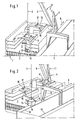
- Figures 1 - 11 of the drawing show - highly schematized - a typical loading or unloading situation when handling general cargo from a cargo ship 1 to pier 2 of a port (Ship unloading), or vice versa, from the pier 2 into the hold 3 of a ship 1 (Ship loading), each with the help of a pier crane 4, whereby from (in the drawing not recognizable) free end of the jib 5 of the crane 4 hangs down a rope 6 the free lower end of which is arranged as a "harness" stop means 7 by means of its general cargo (here: one envelope unit designated in total by 8) to attach to the crane 4, and to be raised by means of a winch, not shown in detail is.
- a "harness" stop means 7 by means of its general cargo (here: one envelope unit designated in total by 8) to attach to the crane 4, and to be raised by means of a winch, not shown in detail is.
- the crane 4 is a in the direction of the double arrow 9 along the Pier 2 on two parallel rails 10 movable gantry crane, the whole designated 11 Upper part about a vertical pivot axis 12 relative to the lower part 13 of the crane 4th is rotatable or pivotable.
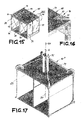
- the envelope unit 8 consists of an envelope hood 14 (see e.g. FIGS. 18, 20, 29, 31, 32, 34, 35) and an envelope basket 15 covered by this (see e.g. FIGS. 15, 16, 17, 19, 29, 31, 32, 34, 35), which will be described in more detail below, as well as, if applicable, that in Envelope basket 15 jammed cargo.
- the cargo hold 3 of the cargo ship 1 has at least one loading or unloading opening 16 is provided, which is often referred to as "loading hatch".
- the cargo space 3 can (as in the exemplary embodiment shown as an example) may be formed over several days, and is otherwise to the outside i.w. closed.
- the hatches 16 of ships 1 usually closed with a lid that can be swiveled up or put on while driving and releasably locked, and opened in the port for loading or unloading.
- the 1 - 11 show an example of a ship 1 with three loading decks arranged one above the other, and FIGS. 14, 30, 34 and 35 four and five "loading levels" lying one above the other in parallel.
- the middle cargo area below the respective hatch 16 is shaft-like recessed in order to load and unload the individual decks (A-Deck, B-Deck etc.) to be able to, although this area also generally is loaded, as below is explained.
- a cover designated as a whole is placed on an (at least partially opened) loading hatch 16, which means that the conventionally available clear opening area of a loading hatch 16 is in each case approximately 10%. (e.g. from approx. 150 m 2 to 15 m 2 ) is reduced.
- the cover is explained further below with reference to FIGS. 12, 13 and FIGS. 21-28, 30, 34 and 35 using preferred exemplary embodiments.
- the cover 17 itself has a (closable) through opening has which is of a size and shape such that it the outer contours a cover unit 8 or its cover 14 is adapted, the cover 17 can be provided with a covering means 18, which has its through opening in the idle state I. W. closes rainproof, but which when retracting an envelope unit 8 - e.g.
- the handling system according to the invention is intended especially a weather-protected loading and unloading of transport vehicles - without additional conveyor systems - take place, namely in the specific embodiment Deleting so-called fruit pallets from a banana freighter.
- the loading hatches are first 16 (at least partially) open, and those closed during the crossing will be closed and locked hatch covers of the loading hatches 16 each according to the invention by a cover 17 replaced.
- This is usually done with on-board dishes (i.e. with the ship firmly attached installed ship winches or the like), but can also be used if necessary by means of a pier crane 4 or the like. carried out, who then (as the only funding) carries out the loading. It can ever Depending on the circumstances of the individual case, a crane 4 may be used, possibly and but preferably also several of them (see FIGS. 14, 34).
- Deviating from the highly schematic 1 - 11 come four pier cranes in the specific embodiment 4 used, namely two cranes 4 for each of the two loading hatches 16 of the Freighter 1, like this e.g. 14 with respect to the loading hatch 16 shown there.
- both loading hatches 16 are therefore also provided Provide cover 17 at the beginning of the discharge. In other cases it can be sufficient to work with only one cover 17 16, which is then initially on a first loading hatch 16 is fitted, and possibly later when the unloading or loading process is progressing is converted from this first loading hatch 16 to another loading hatch 16.
- FIG. 1 shows a (later) state in which the one with four fruit pallets 19th loaded envelope basket 15 of the envelope unit 8 attached to the pier crane 4 relative to the cover 14 of the cover unit 8 except for the (bottom) floor 3 'of the loading space 3 of the ship 1 is lowered
- FIG. 2 shows the actual start of an unloading cycle, namely after the pier crane 4 an empty handling unit 8 from the pier 2 straight picked up and hoisted something.
- the handling unit 8 is then pivoted over the ship 1 by means of the pier crane 4 and positioned over a hatch 16 (covered by a cover 17), to then according to the arrow 20 to be lowered onto / into the loading hatch 16.
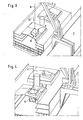
- FIG 3 shows an intermediate state in which the lower section of the envelope unit 8 is located already extends down through the cover 17 into the loading space 3, while the upper section of the handling unit 8 still over the upper edge of the loading hatch 16 protrudes above.
- funnel-shaped baffles or the like that expand upward, for example. on the The top of the loading hatch 16 or the cover 17 covering this during the handling is provided be (see FIGS. 26 and 14, 21, 22, 27, 29, 30, 33a, 34 and 35), or / and also - as in the embodiment. 1 - 11 - other positioning or centering means.
- a control device not shown in detail, is provided by means of which each have an envelope unit 8 to be moved into the loading hatch 16 from above their lowering over / into the loading hatch 16 automatically centered on the loading hatch 16 or one is to be arranged beforehand on this positioned cover 17.
- a guide beam emitter not shown in the drawing arranged, the - similar to an orientation beacon at airports, which when landing an aircraft is used as an orientation aid - for example from a laser beam or the like. can exist.
- the envelope units 8 each have at least one Sensor (preferably several sensors) provided, the actual distance of the Cover unit 8 or the respective sensor to the beacon, and a corresponding Signal transmitted to a control device, also not shown in the drawing, in / by means of which this actual value is compared with a predetermined target value, and a control signal if the actual value deviates from the respective target value is initiated for a countermeasure by means of which the actual value / target value deviation short term i.w. to zero (at least to a harmless or unproblematic one Value) is to be reduced.
- Sensor preferably several sensors
- Such a countermeasure can obviously be carried out in many different ways, namely, for example, by pivoting or moving the boom. But since this again with the impression of a further pendulum movement or reinforcement of the existing one Pendulum movement of the crane load can be connected, it has proven to be particularly useful underlined to provide and implement such a countermeasure as close to the load as possible, So, for example.
- a "rope brake” or the like particularly simply by at least for Partly movable stops, which are most useful relatively short above the anchor point can be automatically driven to the crane cable 6, which is basically an additional device of the pier crane 4, but it has been shown that it (considerably) It is more appropriate if such a "rope brake” or the like. in the area of each hatch 16 is mounted, because you then "self-sufficient" and not on the respective equipment of the the respective port handling facility is instructed.
- the cover 17 - also automatically - opened so far that the envelope basket 15 can pass through it downwards, and now the loading hatch 16 is closed rainproof upwards / outwards by the cover hood 14, the (still empty) envelope basket 15 of the envelope unit 8, the four ropes 21 with the envelope hood 14 is connected - which are part of a winch system of the handling unit 18, that can be seen independently of the pier crane 4 (to be operated) - lowered downwards, in present case down to the floor 3 'of the loading space 3 in order to be there with four fruit pallets 19th to be loaded (see Fig. 6).
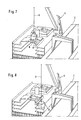
- the (with four fruit pallets 19) loaded envelope 15 is then again (in the direction of the arrow 22) by means of the ropes 21 or the above-mentioned winch system up into the Cover hood 14 hoisted, and the now loaded envelope unit 8 is then by the pier crane 4 raised (see FIG. 7).
- the cover 17 closes again automatically and in turn now forms protection against the cargo hold Precipitation, sand, etc.
- FIGS. 12 and 13 are also highly schematic, however, the principle of the cover (s) according to the invention is basically exemplary without reveal more:
- the cover 18 of each cover 17 i.w. approximately be designed like a diaphragm of a camera, the diaphragm segments using suitable Controllers are to be controlled, which signal an approach of a handling unit 8, and hereby trigger corresponding control signals in the control device which open them cause the aperture segments, to the extent that the relevant envelope unit 8 in cover 17 is to be retracted. Then another control signal ensures that the Aperture elements sealing during the loading or unloading process to the outside of the Handling unit 8 can be moved up.
- the covers 17 each have a frame 23 which, when the cover is removed 17 to an open cargo hatch 16 to form-fit with the cargo hatch 16 or lock is.
- the frame 23 surrounds the (actual) covering means 18, which is the hatch opening closes completely rainproof if there is no handling unit 8 in the loading hatch 16 is retracted, so it is closed by a cover 14, on the one hand also the hold 3 of the ship 1 before the penetration of precipitation, Flying sand and the like to preserve, on the other hand, however, the fastest possible or to be able to carry out the loading process, i.e. also an envelope unit 8 (namely by means of the pier crane 4 from its crane operator) without unnecessary dead times in one of a cover 17 covered hatch 16 can retract.
- an envelope unit 8 namely by means of the pier crane 4 from its crane operator
- the covering means 18 is in the embodiment shown schematically in FIGS. 12 and 13 from a kind of slat plate, the individual slats 24 each with the two laterally adjacent slats 24 in the manner of a (transversely flexible) tongue and groove connection (rainproof) are connected to each other, so that two each other Adjacent slats 24 are movable / displaceable relative to one another in their longitudinal direction are.
- the area covered by the covering means 18 is essentially divided diagonally, the slats 24 arranged in the cover field 17 'in FIG vertical lines and the lamella 24 located in the cover panel 17 "by horizontal Lines are limited.
- the slats 24 are each facing the slats 24 of the other cover field End face provided with a seal 25, which in the closed state of the cover 17 or its cover means 18 sealing on a side surface of a lamella 24 of the other cover field is present (Fig. 12).
- a handling unit 8 is to be moved into a loading hatch 16 from above by means of the pier crane 4 as soon as the handling unit 8 is centered over the loading hatch 16 positioned and this is approximated - the cover means 18 of the cover 17 is opened so far, as required to accommodate the envelope unit 8, i.e. the slats 24 are, if necessary, from their (complete) closed position recognizable in FIG in accordance with their longitudinal direction. the arrows 26 or 26 'moved outwards until the of the opening they have opened is sufficiently large to accommodate the envelope unit 8 from above to be able to retract the opening.
- the handling unit 8 is positioned accordingly in the loading hatch 16 (see FIG. 4)
- the slats 24 previously involved in the opening process are each counter to the arrows 26 or 26 'moved so far inward that they press their seals tightly 25 rest on the outside of the cover unit 8 or its cover 14 (see FIG. 13), with the result that the loading hatch 16 is closed again / continues rainproof, while loading or unloading of the envelope 15 takes place in the hold 3 of the ship 1.
- the frame 23 on the inside of at least two Legs extending at right angles to one another have such seals 25 ', so that an envelope unit 8 positioned in the loading hatch 16 is sealed all around on its periphery is, and otherwise within the circumferential seals 25, 25 'with the roof surface 36 'of the cover 14.
- FIG. 13 the one already described above can be seen Mode of operation, if necessary, even with a handling unit 8 'with a different width and / or depth practice further.
- the envelope unit drawn with dotted lines in FIG. 13 8 ' which has a smaller width and a smaller depth than the cover unit 8, it obviously only requires the slats 24 after the cover means 18 has been opened (insofar as they are adjusted to the opening process controlled by the outer contour of the envelope unit 8 were involved) a little further from the inside to the outer contour of the handling unit 8 ' or to approach their cover 14.
- FIG. 12 When the leader of the pier crane 4, the loaded handling unit 8 into that shown in FIG. 7 Has raised intermediate position, the covering means 18 has already been replaced by appropriate ones Control closed automatically (Fig. 12), so that even after moving out the handling unit 8 from the loading hatch 16 no significant precipitation or contamination can penetrate into the hold 3 of the ship 1 from the outside.
- the crane operator pivots the loaded envelope unit 8 according to the intermediate position.
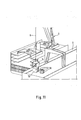
- Fig. 8 on the Pier 2 and then lowers the envelope basket 8 by means of the winch arrangement described above relative to the cover 14 so far that it stands on the pier 2 (Fig. 9), and the four fruit pallets 19 one after the other, in pairs or simultaneously from the Envelope basket 15 can be unloaded.
- Fig. 10 shows this state with two Cover basket 15 of fruit pallets 19 removed, and FIG. 11 with four removed, fruit pallets 19 placed side by side at the intended storage location.
- the crane operator then pulls the envelope 15 again by means of the winch arrangement into the cover 14 (see also FIG. 2), and pivots the cover unit 8 again up to the loading hatch 16, where it automatically centers and then into the loading hatch 16 (with simultaneous independent partial opening of the cover means 18 of the cover 17) is lowered (Fig. 3) until the state acc. Fig. 4 has been reached again, and the Envelope basket 15 can in turn be loaded with four fruit pallets 19.
- the empty swiveling back of the handling unit 8 from the pier 2 in the loading hatch 16 can be avoided by already having new / different cargo the pier 2 is added and when the loading unit 8 is pivoted back into the receiving hatch 16 ultimately stowed in the hold of ship 1 or, if necessary, temporarily stored on the ship becomes.
- FIG. 14 first of all shows a representation similar to FIG. 1 or FIG. 4 with an envelope unit 8, as explained in detail later with reference to FIGS. 15-20 and 31, 32 is, and further with the difference that the hatch 16 recognizable in Fig. 16 of the im Cutout cargo ship 1 is served by two pier cranes 4. Even the cover 17 differs considerably from that above by way of example with reference to FIG. 12 and 13 explained. It is described below in particular with reference to FIGS. 21-28 and 30 and 33-35 discussed in detail. 14 therefore shows a loading or unloading state, at which an envelope unit 8 on a hatch 16 covered by a cover 17 Cargo ship 1 is placed sealingly.
- the (ship's own) hatch cover 27 in right-hand part of the loading hatch 16 is half open, the part assigned to the cover 14
- the envelope basket 15 is still inside the envelope hood 14, that is to say still is not lowered onto the corresponding ship deck.
- Another handling unit 8 ' is on the second pier crane shown on the right in FIG. 14 4 'struck. Their (still empty) envelope basket 15 'is relative to their envelope hood 14' lowered down.
- FIG. 15 shows an i.w. conventional envelope basket 15 for four fruit pallets 19, which are indicated schematically in FIG. 15 with dash-dotted lines.
- a lifting device such as a forklift, pallet truck or the like. into the two each other opposite, open sides of an envelope 15 to retract, and on her Bottom 28 are to be set down so that they do not follow the outer contour of the basket frame 29 protrude outside.
- the envelope basket 15 shown in FIG. 15 is compared to conventional envelope baskets I. W. modified only with regard to its four suspension points 30. To explain this and 15, which is framed with a dash-dotted circle in FIG. 15 and with XVI designated upper right corner shown in Fig. 16 enlarged. It can be seen that on the top of this so-called 4-piece pallet basket 15 covered with a plate 31 each upstanding tab 32 is welded, each with a horizontal through hole 33 is provided so that the pallet basket 15 at the four corners of its top can be posted. The net weight of such a 4-piece pallet basket is approx. 1.3 t, its payload is about 4.4 t.
- the envelope basket 15 according to. 15 and 16 after placing the cover 14 associated with it on the (further below in individually described) frame 23 on the loading hatch 16 can no longer be rotated. There this is disadvantageous for the loading and unloading process in the case of the invention
- the method preferably uses the envelope basket 15 ′′ shown in FIG. 17, which instead of a Four-point suspension can be attached centrally and rotated about its longitudinal central axis 34. In order to deflect it sideways and / or to turn it around the axis 34 of the or to keep the discharge opening 16 of the retracted envelope basket 15 "within narrow limits, the stop connector 35 of the envelope basket 15 "is provided with a pendulum damping.
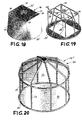
- FIG. 18 shows an example of the design of part of a cover 14, namely its cover outer tarpaulin 36, which on the i.w. cuboid, widening conically downwards Frame 29 (see FIG. 19) of the cover 14 is placed around its top and Side surfaces during transportation by crane 4 or 4 'before weather influences and protect pollution.
- the frame 29 closes at the bottom with a ring 29 ', so that the tarpaulin is designed accordingly, that is, from its rectangular upper side 36 '- widening downwards - ultimately merging into an annular section.
- hood 14 for a rotatable envelope basket 15
- a rotatable envelope basket 15 see e.g. Fig. 17
- the hood roof is 37 - and therefore a matter of course also the section of tarpaulin 36 there - i.w. funnel-shaped, so also protect the parts protruding from the hood roof (e.g. 35 or 38) are.
- FIG. 21 shows a section of a cargo ship 1 containing a loading hatch 16, as well can already be seen in FIG. 14, on an enlarged scale compared to FIG. 14, and without already mounted loading unit 8. The details of this are in the following FIGS. 22 to 28 shown.
- the total designated 17 cover of the loading hatch 16 initially includes one mentioned above in connection with FIGS. 1 to 13, in particular FIGS. 12 and 13 (Basic) frame 23 (see also Fig. 24), which after opening the ship's own Loading hatch cover 27 (already opened in FIG. 21) is placed on loading hatch 16, and on its upper side two parallel slide rails 40 arranged at a distance from one another, 40, on which a carriage 42 (see also Fig. 27) with one from top to bottom tapering introduction funnel 41 (see also Fig. 26) is slidably displaceable, by means of Sliding shoes 43, one of which is shown in FIG. 28.
- cover 17 has sliding elements 18 'as cover means 18 (see also FIG. 23), the i.w. consist of trapezoidal sheets 44 which are arranged on a cover frame 45, a weather protection cover for the one lying next to the introduction funnel 41 To form section of the loading hatch 16.
- Each sliding element 18 ' is based on the so-called drawer principle guided by rollers 46 in a guide profile, and each together with the Move carriage 42.
- the trapezoidal sheets 44 are inclined transversely to the ship by approximately 3 ° to ensure an outflow of rainwater.
- FIG. 24 shows in a single illustration the frame 23 already mentioned repeatedly, on which the carriage 42 (see FIG. 27) can be moved in a sliding manner, specifically by means of one Electric slide drive, not shown.
- the one in FIG. 26 is therefore isolated shown basket-shaped guide 41 which, when a loading unit 8 is placed on it, leads to the insertion opening 47 centered, placed on a platform 48, which together with the Injecting funnel 41 forms the carriage 42, which in turn is placed on the (basic) frame 23 is attached, and (only) covers part of the loading hatch.
- the one (s) not from that Carriage 42 covers section (s) of loading or unloading opening (loading hatch) 16 each covered by the covering means 18 of the cover 17 in a rainproof manner, in the present case Ausrrockungsbeispiel thus of the telescopic sliding elements 18 'as it were.
- these are moved together largely overlapping one another, and in the left-hand part of FIG. 21, they have moved apart substantially less overlapping, so that the open part of the loading hatch 16 is completely covered when one Transfer unit 8 onto the insertion opening 47 of the introduction funnel 41 or slide 42 is put on.
- the key pallets 19 are each struck and by means of unload the crane 4 or 4 'used (or an on-board crane), to begin with space for an envelope basket that can be lowered into the loading space 3 15 or 15 'or 15 "to create, as well as for pallet trucks, by means of which the other Fruit pallets must be placed in a retracted envelope basket 15.
- the cover 17 can be moved using one of the existing pier cranes 4, 4 'or, if necessary, also by means of an on-board crane on the open area of the Luke 16 lowered and locked there. This state is shown, for example, in FIG. 30.
- the cargo from a hatch 16 is then with two pier cranes 4, 4 'deleted (see Fig. 34).
- the insertion opening 47 provides the following:
- the crane operator moves the handling unit 8 to a approach height within the height difference between the water-side inlet funnel 41 and the land-side inlet funnel 41 '(see Fig. 29). This ensures that the cover 14 of the cover unit concerned 8 strikes the water-side introduction funnel 41 and can be safely lowered into it can.
- the envelope basket 15 can be seen extremely from the ideal location to Threading deviate without thereby endangering safe instruction.
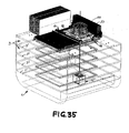
- the introduction funnel 41 or 41 ' has a recess 50 on which the cover 14 when crane rope 6 is lowered further, while the basket 15 continues is lowered onto the working deck to be processed (here: to be emptied), as this can be seen by way of example in FIGS. 34 and 35.
- the envelope basket 14 is then with the help of pallet trucks with four fruit pallets 19th load that retracted into the envelope basket 15 on its two open sides and then be dropped off; be discontinued; be deducted; be dismissed. Then the loaded envelope basket 15 is in the envelope hood assigned to it 14 lifted in, which - as stated - on the recess 50 of the introductory funnel 41 is parked, and the handling unit is moved over the crane rope 6 by the one in use Pier crane 4 or 4 'transported to the land side and set down on pier 2. There can the fruit pallets 19, for example, by a forklift with a double fork removed and temporarily stored or immediately on a conveyor or on refrigerated trucks, railway refrigerated wagons or the like be taken over.
- Landside handling can basically be done in an analogous manner, so it differs in this respect of the procedure described above with reference to FIGS. 1-11 (see in particular the 9-11).
- Various options are available for this. So at the pier (or of course also at another storage or drop-off point) e.g. a drop-off table or board 51 may be present, as shown by way of example in FIG.
- an introduction funnel 41 ' has a recess corresponding to recess 50 of introductory funnel 41, on which the cover 14 is retained when a cover unit 8 is put on can, in order to lower the envelope basket 15 further.
- the introductory funnel can 41 ' may only be designed as a funnel sector, as indicated in FIG. 29 on the side of the settling table 51 facing the country, but can be seen this introductory funnel 41 'may also be formed all around.
- the light Height H between the underside of the table top 52 and the floor is at least as large like the height of the envelope basket 15 so that it can be freely lowered and unloaded.
- the height H (at least) is so great that a conventional forklift below drive the settling table 51 or its table top 52, and fruit pallets 19 from the envelope basket 15 can discharge.
- Another option for practical onshore handling is, for example, that the path of the cover 14 during the landward lowering process of a handling unit 8 or the like by attachment to a spring-loaded cable drum. so limited is that the cover 14 in a predetermined height position above the respective Storage space (e.g. a pier 2) remains in height while the envelope basket 15 the loading unit 8 hanging on the crane cable 6 is further lowered until it touches down.
- a predetermined height position above the respective Storage space e.g. a pier 2
- Handling units 8 to be used without a separate drive of their own, still various other configurations possible.
- the handling system according to the invention can of course also be used in a highly advantageous manner for all possible other applications in which goods to be handled between two storage locations are simple and yet it should be handled quickly, at least one of which is a weather-protected area, and the transhipment path between the two (possibly intermediate) storage locations is at least partially affected by environmental influences such as precipitation, flying sand, solar radiation or the like. is / may be exposed.
Landscapes
- Engineering & Computer Science (AREA)
- Ocean & Marine Engineering (AREA)
- Aviation & Aerospace Engineering (AREA)
- Mechanical Engineering (AREA)
- Ship Loading And Unloading (AREA)
- Warehouses Or Storage Devices (AREA)
- Forklifts And Lifting Vehicles (AREA)
Abstract
Description
- Fig. 1
- eine perspektivische Teildarstellung eines (Hafen-)Piers, eines Pier-Krans, und eines Frachtschiffes, sowie einer erfindungsgemäßen Umschlageinrichtung in einer Draufsicht schräg von oben gesehen, und zwar bei auf die Ladefläche des Laderaums abgesenktem, beladenem Umschlagkorb;
- Fig. 2
- (in einer Darstellung i.w. gem. Fig. 1) die Darstellung gem. Fig. 1, wobei eine leere Umschlageinheit gerade von dem Pier-Kran aufgenommen worden ist;
- Fig. 3
- eine i.w. den Fig. 1 und 2 entsprechende Darstellung, wobei die leere Umschlageinheit gerade in eine zum Laderaum des Schiffes führende Ladeluke von oben her eingefahren wird;
- Fig. 4
- eine i.w. den Fig. 1 - 3 entsprechende Darstellung, wobei der leere Umschlagkorb relativ zu der Umschlaghaube der Umschlageinheit bereits teilweise abgesenkt ist, und die Ladeluke durch die Umschlaghaube regen- und staubdicht verschlossen ist;
- Fig. 5
- eine i.w. den Fig. 1 - 4 entsprechende Darstellung, wobei der Umschlagkorb in seine Decksposition auf die Ladefläche des Laderaums abgesenkt ist;
- Fig. 6
- eine i.w. den Fig. 1 - 5 entsprechende Darstellung, wobei der - zwei Beladeabteile aufweisende - Umschlagkorb zwischenzeitlich mit Umschlaggut beladen ist, nämlich mit vier Fruchtpaletten;
- Fig. 7
- eine i.w. den Fig. 1 - 6 entsprechende Darstellung, wobei der beladene Umschlagkorb wieder (wie in Fig. 2 im leeren Zustand) in die Umschlaghaube eingezogen worden ist, und die gesamte Umschlageinheit soweit angehoben worden ist, daß sie von der Ladeluke frei ist;
- Fig. 8
- eine i.w. den Fig. 1 - 7 entsprechende Darstellung, wobei die beladene Umschlageinheit von dem Pier-Kran aus der Position gem. Fig. 7 zwischenzeitlich in Richtung zur Pier/auf die Kaje geschwenkt worden ist;
- Fig. 9
- eine i.w. den Fig. 1 - 8 entsprechende Darstellung, wobei der Umschlagkorb zwischenzeitlich auf der Pier abgesetzt und die Umschlaghaube relativ zu dem Umschlagkorb soweit von dem Pier-Kran angehoben worden ist, daß der Umschlagkorb frei (zugänglich) ist;
- Fig. 10
- die Darstellung gem. Fig. 9, wobei zwei Ladeeinheiten zwischenzeitlich aus dem Umschlagkorb entladen und - neben dem Umschlagkorb - auf der Pier abgestellt worden sind;
- Fig. 11
- eine Darstellung gem. 10, wobei der Umschlagkorb zwischenzeitlich von seinem gesamten Umschlaggut (vier palettengestützte Ladeeinheiten) entladen ist, so daß ggf. ein neuer Entladezyklus eingeleitet werden kann;
- Fig. 12
- eine (schematische) Draufsicht auf eine Abdeckung in einem auf eine Ladeluke aufgesetzten, montierten, geschlossenen Zustand;
- Fig. 13
- die Abdeckung gem. Fig. 12 in einem teilweise geöffneten, (dennoch) regendichten Zustand mit einer in die Abdeckung (sowie damit die Ladeluke) von oben her eingefahrenen Umschlageinheit;
- Fig. 14
- eine Fig. 1 entsprechende, bzgl. des Umschlagkorbes und der Umschlaghaube weniger schematisierte Darstellung, wobei - abweichend von Fig. 1 - im rechten Teil zusätzlich der (ein) Pier-Kran auch noch mit einer im PierBereich an ihn angeschlagenen Ladeeinheit dargestellt ist;
- Fig. 15
- ein gegenüber der konventionellen Ausbildung leicht modifizierter Palettenkorb in perspektivischer Darstellung;
- Fig. 16
- die in Fig. 15 mit einem strichpunktierten Kreis umrandete und mit XVI bezeichnete Einzelheit an einer oberen Ecke des (i.w. konventionellen) Palettenkorbes mit der dort vorgesehenen Eck-Aufhängung;
- Fig. 17
- einen um seine Längsmittelachse im angeschlagenen Zustand drehbaren Palettenkorb;
- Fig. 18
- eine Umschlaghaube mit Abdeckplane in perspektivischer Darstellung;
- Fig. 19
- die Umschlaghaube gem. Fig. 18 ohne Abdeckplane;
- Fig. 20
- eine zylindrische Abdeckplane für einen drehbaren Palettenkorb gem. Fig. 17;
- Fig. 21
- eine mit einer Abdeckung abgedeckte Ladeluke eines Schiffes in stark verkleinerter, perspektivischer Darstellung;
- Fig. 22
- die Ladeluken-Abdeckung der Darstellung gem. Fig. 21;
- Fig. 23
- ein Abdeckelement der Ladeluken-Abdeckung gem. den Fig. 21 bzw. 22;
- Fig. 24
- einen Grundrahmen der Ladeluken-Abdeckung gem. den Fig. 21 bzw. 22 in (gegenüber den Fig. 21, 22) vergrößerter Darstellung;
- Fig. 25
- eine zur Abdeckung gem. den Fig. 21, 22 gehörende Plattform;
- Fig. 26
- einen zur Ladeluken-Abdeckung gem. den Fig. 21, 22 gehörenden Einweistrichter;
- Fig. 27
- einen aus der Plattform gem. Fig. 25 sowie dem Einweistrichter gem. Fig. 26 bestehenden, auf dem Grundrahmen gem. Fig. 24 verfahrbaren Schlitten;
- Fig. 28
- einen gegenüber den Fig. 21 - 27 stark vergrößerten Gleitschuh des auf dem Grundrahmen gem. Fig. 24 verfahrbaren Schlittens gem. Fig. 27;
- Fig. 29
- ein Ausführungsbeispiel einer landseitigen Palettenentnahme mit einem mit einer Durchgangsöffnung versehenen Absetztisch, an dessen Oberseite ein der Durchgangsöffnung zugeordnetes Einweissegment angeordnet ist, wobei bei der Darstellung gem. Fig. 29 eine Umschlaghaube über der Durchgangsöffnung abgesetzt ist, und der ihr zugeordnete Umschlagkorb relativ zu der Umschlaghaube bereits auf die als Lager- und Transportfläche dienende Pier abgesenkt ist;
- Fig. 30
- eine i.w. Fig. 21 entsprechende Darstellung, anhand welcher der Funktionsablauf erläutert wird;
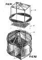
- Fig. 31
- einen (nicht drehbaren) Palettenkorb nebst über diesem angeordneter Umschlaghaube (ohne Abdeckplane);
- Fig. 32
- einen um seine Mittellängsachse drehbaren Palettenkorb gem. Fig. 17, der von der ihm zugeordneten Umschlaghaube (gem. Fig. 20) i.w. überdeckt ist;
- Fig. 33
- eine stark schematisierte Draufsicht auf eine Be- bzw. Entladeöffnung (Ladeluke) mit Abdeckung (a)) bzw. ohne Abdeckung (b));
- Fig. 34
- eine i.w. Fig. 14 entsprechende Darstellung, bei welcher der Umschlagkorb der auf die Ladeluke aufgesetzten Ladeeinheit zwecks Entladung in den Laderaum eines Schiffes abgesenkt ist, während die Ladeluke von der Abdekkung abgedeckt ist, und die freie Durchgangsöffnung des Einweistrichters von der Umschlaghaube überdeckt ist; und
- Fig. 35
- eine vergrößerte Teildarstellung des linken (Schiffs-)Teils von Fig. 34, bei welcher der Ladekorb durch die Ladeluke bis auf das vierte Ladedeck des Laderaums abgesenkt ist.
| Bezugszeichenliste | |||
| 1 | Schiff (Fracht-) | ||
| 2 | Pier | ||
| 3 | Laderaum (von 1) | 3' | Boden (von 3) |
| 4; 4' | (Pier-) Kran | ||
| 5 | Ausleger (von 4) | ||
| 6 | (Kran-)Seil | ||
| 7 | Anschlagmittel ("Geschirr") | ||
| 8; 8' | Umschlageinheit | ||
| 9 | Doppelpfeil | ||
| 10 | Schienen | ||
| 11 | Oberteil (von 4) | ||
| 12 | (vertikale) Schwenkachse (von 11) | ||
| 13 | Unterteil (von 4) | ||
| 14; 14' | Umschlaghaube | 14" | Dachfläche (von 14) |
| 15; 15'; 15" | Umschlagkorb | ||
| 16 | Be- bzw. Entladeöffnung ("Ladeluke") | ||
| 17 | Abdeckung | 17', 17" | Abdeckungsfelder |
| 18 | Abdeckmittel (von 17) | 18' | Gleitelemente |
| 19 | Fruchtpaletten | 19' | Flachpalette (von 19) |
| 19" | Schlüsselpaletten | ||
| 20 | Pfeil | ||
| 21 | Seite | ||
| 22 | Pfeil | ||
| 23 | Rahmen | ||
| 24 | Lamellen | ||
| 25; 25' | Dichtungen | ||
| 26; 26' | Pfeile | ||
| 27 | schiffseigene Ladeluken-Abdeckung | ||
| 28 | Boden (von 15) | ||
| 29 | Korbrahmen | 29' | Rahmenring |
| 30 | Aufhängepunkte (von 15; s. Fig. 15, 16) |
| 31 | Platte (von 15) | ||
| 32 | Lasche | ||
| 33 | Durchgangsbohrung (von 32) | ||
| 34 | Längsmittelachse | ||
| 35 | Anschlagstutzen (von 15'') | ||
| 36 | Plane | 36' | Oberseite (von 36) |
| 37 | Haubendach | ||
| 38 | Seilrollen | ||
| 39 | Seil | ||
| 40 | Gleitschienen | ||
| 41; 41' | Einweistrichter | ||
| 42 | Schlitten | ||
| 43 | Gleitschuhe | ||
| 44 | Trapezbleche | ||
| 45 | Abdeckrahmen | ||
| 46 | Rollen | ||
| 47 | Einführöffnung | 47' | Durchgangsöffnung (von 52) |
| 48 | Plattform | ||
| 49 | Kühlcontainer | ||
| 50 | Rezess (von 41 bzw. 41') | ||
| 51 | Absetztisch | ||
| 52 | Tischplatte |
Claims (47)
- Verfahren zum Umschlagen von zu transportierenden (Umschlag-)Gütern, insb. Stückgut, insb. (vorzugsweise verpacktem) Obst oder Gemüse, insb. Bananen, insb. i.a. i.w. quader- oder würfelförmigen Ladeeinheiten (8), bestehend aus mehreren - ggf. auf einer Transport-Flachpalette od.dgl. - übereinander gestapelten Lagen aus in Behältnissen, wie z.B. (i.a. i.w. quaderförmigen) Pappkartons od.dgl. verpackten Bananen(stauden) od.dgl ("Fruchtpaletten" (19)), von einer ersten (ggf. Zwischen-)Lagerstelle (z.B. 3) an eine zweite (ggf. Zwischen-)Lagerstelle (z.B. 2), insb. zum Be- bzw. Entladen eines Fahrzeuges, insb. eines Schiffes (1), welches (wenigstens) einen mit (wenigstens) einer verschließbaren Be- bzw. Entladeöffnung ("Ladeluke") (16) versehenen, im übrigen nach außen i.w. geschlossenen Laderaum (3) aufweist, wobei das jeweils umzuschlagende (Umschlag-)Gut (19) an seiner momentanen Lagerstelle (3 bzw. 2) jeweils stück- oder chargenweise in einen Förderbehälter (15) verbracht wird, der beladene Förderbehälter (15) an ein Fördermittel übergeben, insb. an ein Hebezeug (4) angeschlagen wird, und mittels des Hebezeuges (4) von seiner ersten Lagerstelle (z.B. 3) durch die Ladeluke (16) hindurch zu einer zweiten Lagerstelle (z.B. 2) (bzw. einem Zwischenförderer) transportiert wird, gekennzeichnet durch folgende Verfahrensschritte (die nicht notwendigerweise alle in der nachfolgenden Reihenfolge durchgeführt zu werden brauchen):1.1 (wenigstens teilweises) Öffnen der betreffenden Ladeluke (16);1.2 wenigstens teilweises (Wieder-)Verschließen der nach dem Öffnen der Ladeluke (16) freigelegten lichten (Ladeluken-)Durchgangsöffnung mittels einer an/auf der Ladeluke (16) zu positionierenden Abdeckung (17) und/oder einer Umschlageinheit (8 - 14, 15), letztere bestehend aus1.2.1 einer die Ladeluke (16) zumindest i.w. (regen-)dicht verschließenden Umschlaghaube (14), und1.2.2 einem von der Umschlaghaube (14) überdeckten bzw. übergriffenen, Umschlaggut (19) enthaltenden bzw. mit Umschlaggut (19) zu beschikkenden Umschlagkorb (15) od.dgl., wobei der Umschlagkorb (15) in einer Transportstellung eng benachbart unterhalb der Umschlaghaube (14) angeordnet wird;1.3 Absenken des (Umschlag-)Korbes (15) aus der Umschlaghaube (14) auf das jeweils vorgesehene Be- bzw. Entladeniveau;1.4 Be- bzw. Entladen des Umschlagkorbes (15) mit bzw. von Umschlaggut (19);1.5 Anheben des Umschlagkorbes (15) relativ zur Umschlaghaube (14) bis in seine Transportstellung;1.6 Anheben der gesamten Umschlageinheit (8) sowie deren Umsetzen auf die zweite Lagerstelle (z.B. 2) bzw. ein zur zweiten Lagerstelle (z.B. 2) führendes Fördermittel;1.7 Absenken des Umschlagkorbes (15) relativ zur Umschlaghaube (14) an der zweiten Lagerstelle; und1.8 Ent- bzw. Beladen des Umschlaggutes (19) aus dem bzw. in den Umschlagkorb (15).
- Verfahren nach Anspruch 1, dadurch gekennzeichnet, daß die Umschlageinheit (8) mittels eines (ersten) Hebezeuges (4) umzusetzen ist.
- Verfahren nach Anspruch 1 oder 2, dadurch gekennzeichnet, daß die Ladelukenöffnung nach dem (wenigstens teilweisen) Öffnen der Ladeluke (16) mittels einer (einen vorzugsweise transportablen Wetterschutz bildenden) Abdeckung (17) wenigstens teilweise verschlossen wird.
- Verfahren nach einem oder mehreren der vorhergehenden Ansprüche, dadurch gekennzeichnet, daß die Umschlaghaube (14) beim/nach dem Positionieren (i.a. Absetzen) der Umschlageinheit (8) an (i.a. auf) der Ladeluke (16) bzw. der an ihr angeordneten Abdeckung (17) mit der Ladeluke (16), bzw. mit deren an ihrem Rand umlaufenden Ladeluken-Rahmen od.dgl., bzw. mit der Abdeckung (17), bzw. deren an ihrem Außenrand umlaufenden Rahmen (23) od.dgl. lösbar zu verriegeln ist.
- Verfahren nach Anspruch 4, dadurch gekennzeichnet, daß die Umschlaghaube (14) bei ihrem Verriegeln selbsttätig abgedichtet wird.
- Verfahren nach einem oder mehreren der vorhergehenden Ansprüche, dadurch gekennzeichnet, daß die Abdeckung (17) mittels eines zweiten Hebezeuges (u.a. mit 21) auf der/einer Ladeluke (16) zu montieren bzw. von ihr zu demontieren ist.
- Verfahren nach Anspruch 6, dadurch gekennzeichnet, daß die Abdeckung (17) mittels eines der/einer Ladeluke (16) zugeordneten zweiten Hebezeuge (u.a. mit 21) zu handhaben ist, im Falle eines zu be- bzw. entladenden Schiffes (1) bspw./insb. mittels eines bordeigenen Geschirrs.
- Verfahren nach einem oder mehreren der vorhergehenden Ansprüche, dadurch gekennzeichnet, daß die Umschlageinheit (8) und/oder die Abdeckung (17) mittels eines Steuersystems und/oder ggf. einer Führungseinrichtung so gesteuert wird, daß sie spätestens in einer der Ladeluke (16) benachbarten Stellung selbsttätig zur Ladeluke (16) zentriert wird.
- Verfahren nach Anspruch 8, dadurch gekennzeichnet, daß das Steuerungssystem u.a. einen "lernfähigen" Rechner aufweist, dem die Positionskoordinaten der/einer Umschlageinheit (8) bei Annäherung an die Ladeluke (16) durch von entsprechenden Gebern erzeugte elektrische Signale zugeleitet werden, und der unter Verwendung dieser Signale (ggf. bei einer Optimierung) eine "Idealsteuerung" errechnet, deren Steuersignale bei nachfolgenden ähnlichen/gleichen Umschlageinheiten (8; 8') für das entsprechende Hebezeug bzw. diesem zugeordnete Steuer- und/oder Führungseinrichtungen verwendet werden.
- Verfahren nach einem oder mehreren der vorhergehenden Ansprüche, dadurch gekennzeichnet, daß eine/jede Umschlageinheit (8) mittels zweier voneinander unabhängiger Förder- bzw. Transportsysteme gefördert wird, wobei mittels des einen (ersten) Förder- bzw. Transportsystem der Umschlag zwischen der ersten Lagerstelle (z.B. 3) und der Ladeluke (16) durchgeführt wird, und mittels des zweiten Förder- bzw. Transportsystems der Umschlag: zwischen der Ladeluke (16) und der zweiten Lagerstelle (z.B. 2).
- Verfahren nach Anspruch 10, dadurch gekennzeichnet, daß das Einsatzgebiet des ersten Förder- bzw. Transportsystems i.w. an der Oberkante der Ladelukenöffnung endet, und das Einsatzgebiet des zweiten Förder- und Transportsystems dort beginnt.
- Verfahren nach einem oder mehreren der vorhergehenden Ansprüche, dadurch gekennzeichnet, daß die (wenigstens teilweise) geöffnete Ladeluke (16) nach ihrem Öffnen mit einer im Ruhezustand regendicht verschlossenen Abdeckung (17) abgedeckt wird, welche so weit geöffnet ist, bzw. beim Absenken einer Umschlageinheit (8) auf bzw. in die Ladeluke (16) soweit geöffnet wird, daß die Umschlageinheit (8) in die Ladeluke (16) bzw. die an dieser positionierte Abdeckung (17) eingefahren werden kann, und welche nach dem Ausfahren der Umschlageinheit (8) aus der Ladeluke (16) bzw. aus der an ihr positionierten Abdeckung (17) wieder verschlossen wird.
- Verfahren nach Anspruch 12, dadurch gekennzeichnet, daß das Öffnen und/oder Verschließen der Durchgangsöffnung der Abdeckung (17) so gesteuert wird, daß es jeweils selbsttätig erfolgt.
- Verfahren nach einem oder mehreren der vorhergehenden Ansprüche, dadurch gekennzeichnet, daß zum Entladen einer zweiten Lagerstelle, bspw./insb. einem unterhalb einer Be- bzw. Entladeöffnung ("Ladelucke") (16) i.w. vollständig beladenen Laderaum (3), insb. einem Schiffs-Ladedeck (3'), zunächst das unmittelbar unterhalb der Be- bzw. Endladeöffnung (16) gestaute Stückgut (19") sowie ggf. das hierzu benachbarte Stückgut (19") ("Schlüssel-Stückgut" = key load units) in konventioneller Weise einzeln nacheinander entladen wird, bevor nach dem Verfahren gem. Anspruch 1 bzw. einem der hierauf zurückbezogenen Unteransprüche 2 - 13 weitergearbeitet wird.
- Einrichtung zum Umschlagen von zu transportierenden (Umschlag-)Gütern zur Durchführung des Verfahrens nach einem oder mehreren der vorhergehenden Ansprüche, mit wenigstens einem Fördermittel, insb. einem Hebezeug (4), und wenigstens einem an das Fördermittel (Hebezeug) (4) anschlagbaren Förderbehälter (15), gekennzeichnet durch wenigstens eine Umschlageinheit (8 - 14, 15) i.w. bestehend aus einer Umschlaghaube (14), mittels welcher das Fördergut (19) insb. beim Freiluftumschlag zu überdecken ist, sowie eine im Umschlagspfad befindliche Durchgangsöffnung (16) zu einer witterungsgeschützten Ladestelle (3), die beim Be- bzw. Entladen vorübergehend regendicht abzudichten ist, sowie durch einen von der Umschlaghaube (14) überdeckten, Umschlaggut (19) enthaltenden bzw. mit Umschlaggut (19) zu beschickendem Umschlagkorb (15) od.dgl., der in der Umschlaghaube (14) anzuordnen ist, wobei die Umschlaghaube (14) aus einer dem Umschlagkorb (15) benachbarten Transportstellung relativ zu dem Umschlagkorb (15) (begrenzt) bewegbar ist.
- Einrichtung nach Anspruch 15, dadurch gekennzeichnet, daß die Umschlaghaube (14) einen der/einer (Lade-)Durchgangsöffnung (16) bzw. an/auf dieser angeordneten Abdekkung (17) angepaßten Hauben-Rahmen (23) aufweist, der mit dem Umschlagkorb (15) und/ oder der (Lade-)Durchgangsöffnung(16) bzw. deren Abdeckung (17) lösbar zu verriegeln ist.
- Einrichtung nach Anspruch 15 oder 16, dadurch gekennzeichnet, daß die Umschlaghaube (14) so ausgebildet und angeordnet ist, daß sie den Umschlagkorb (15) stets überdeckt.
- Einrichtung nach einem oder mehreren der Ansprüche 15 - 17, gekennzeichnet durch eine Steuereinrichtung sowie ggf. einer Führungseinrichtung, mittels welcher jeweils eine Umschlageinheit (8) und/oder die Abdeckung (17) einer (Lade-)Durchgangsöffnung (16) so zu steuern ist, daß eine Umschlageinheit (8) jeweils in einer der (Lade-)Durch-gangsöffnung (16) benachbarten Stellung (vorzugsweise selbsttätig) zur (Lade-)Durch-gangsöffnung (16) zu zentrieren ist.
- Einrichtung nach Anspruch 18, dadurch gekennzeichnet, daß das Steuersystem u.a. einen "lernfähigen" Rechner aufweist, mit dem die Positionskoordinaten der/einer Umschlageinheit (8) bei Annäherung an eine/die (Lade-)Durchgangsöffnung(16) durch von entsprechenden Gebern erzeugte, elektrische Signale zuzuleiten sind, wobei dieser unter Verwendung dieser Signale (ggf. nach einer Optimierung) eine "Idealsteuerung" errechnet, welche bei nachfolgenden ähnlichen/gleichen Umschlageinheiten (8; 8') als Steuersignale für das entsprechende Hebezeug (4) bzw. diesem zugeordnete Steuer- und/oder Führungseinrichtungen zu verwenden sind.
- Einrichtung nach einem oder mehreren der Ansprüche 15 - 19, dadurch gekennzeichnet, daß eine/jede Umschlageinheit (8) mittels zweier voneinander unabhängiger Förder- bzw. Transportsysteme umzuschlagen ist, von denen das eine (erste) Förder- bzw. Transportsystem (z.B. 4) den Umschlag zwischen der ersten Lagerstelle (2) und der (Lade-)Durchgangsöffnung (16), und das zweite Förder- bzw. Transportsystem den Umschlag zwischen der (Lade-)Durchgangsöffnung (16) und der zweiten Lagerstelle (z.B. 3) durchführt.
- Einrichtung nach einem oder mehreren der Ansprüche 15 - 20, gekennzeichnet durch eine Abdeckung (17), mittels welcher die lichte Durchgangsfläche einer (Lade-)Durch-gangs-öffnung (16) in deren (wenigstens teilweisen) geöffneten Zustand auf einen Bruchteil zu reduzieren ist.
- Einrichtung nach Anspruch 21, dadurch gekennzeichnet, daß die lichte Durchgangsfläche der (Lade-)Durchgangsöffnung (16) mittels der Abdeckung (17) auf etwa 5 - 25 % zu reduzieren ist.
- Einrichtung nach Anspruch 22, dadurch gekennzeichnet, daß die lichte Durchgangsfläche der (Lade-)Durchgangsöffnung (16) mittels der Abdeckung (17) auf etwa 10 % zu reduzieren ist.
- Einrichtung nach einem oder mehreren der Ansprüche 21 - 23, dadurch gekennzeichnet, daß die Abdeckung (17) eine verschließbare Durchgangsöffnung aufweist, deren Größe und Form der Außenkontur der Umschlageinheit (8) bzw. deren Umschlaghaube (14) angepaßt sind.
- Einrichtung nach Anspruch 22, dadurch gekennzeichnet, daß die Abdeckung (17) mit einem Abdeckmittel (18) versehen ist, welches ihre Durchgangsöffnung im Ruhezustand i.w. regendicht verschließt, welche beim Einfahren einer Umschlageinheit (8) (vorzugsweise selbsttätig) zu öffnen ist, und welches sich beim Ausfahren der Umschlageinheit (8) aus der Abdeckung (17) (vorzugsweise selbsttätig) wieder schließt.
- Einrichtung nach einem oder mehreren der Ansprüche 15 - 25, dadurch gekennzeichnet, daß die (Lade-)Durchgangsöffnung (16) und/oder die Abdeckung (17) an ihrer Oberseite mit Führungsmitteln versehen ist, mittels welcher eine in die (Lade-)Durchgangsöffnung (16) von oben her einzufahrende Umschlageinheit (8) bei ihrem Absenken über der/in die (Lade-) Durchgangsöffnung (16) zu positionieren bzw. zu zentrieren ist.
- Einrichtung nach einem oder mehreren der Ansprüche 15 - 26, dadurch gekennzeichnet, daß eine Steuereinrichtung vorhanden ist, mittels welcher jeweils eine von oben her in die (Lade-)Durchgangsöffnung (16) einzufahrende Umschlageinheit (8) bei ihrem Absenken über der/in die (Lade-)Durchgangsöffnung (16) selbsttätig zentrisch zur (Lade-)Durchgangs-öffnung (16) bzw. an/auf ihrer positionierten Abdeckung (17) auszurichten ist.
- Einrichtung nach Anspruch 27, dadurch gekennzeichnet, daß an der/jeder (Lade-)Durchgangsöffnung (16) ein Leitstrahl-Emitter angeordnet ist; daß die Umschlageinheit (8) jeweils mit wenigstens einem Geber (vorzugsweise mehreren Gebern) versehen ist, der (die) seinen Ist-Abstand zum Leitstrahl feststellt (feststellen), und ein entsprechendes Signal erzeugt (erzeugen) sowie zu einer Steuereinrichtung übermittelt (übermitteln), in/mittels welcher diese(r) Ist-Wert(e) mit einem vorgegebenen Soll-Wert verglichen wird (werden), und von welcher bei einem Abweichen des (der) Ist-Werte) vom Soll-Wert Steuersignal(e) für eine Gegenmaßnahme zu erzeugen sind, mittels welcher die Ist-Wert/Soll-Wert-Abweichung(en) rasch i.w. auf Null zu reduzieren ist (sind).
- Einrichtung nach einem oder mehreren der Ansprüche 15 - 28, dadurch gekennzeichnet, daß der Hauben-Rahmen (23) bzw. eine auf diesem angeordnete Plattform (48) od.dgl. relativ zur Be- und Endladöffnungen (16) in wenigstens einer Richtung horizontal verfahrbar ist.
- Einrichtung nach Anspruch 29, dadurch gekennzeichnet, daß der Hauben-Rahmen (23) bzw. die auf diesem angeordnete Plattform (48) od.dgl. (ggf. gleichzeitig) in zwei rechtwinklig zueinander verlaufenden Richtungen horizontal verfahrbar ist, und damit jede beliebige vorgegebene Position über der Be- und Entladeöffnung (16) wählbar anfahren kann.
- Einrichtung nach Anspruch 29 oder 30, dadurch gekennzeichnet, daß der Hauben-Rahmen (23) an seiner Oberseite mit Schienen (40) versehen ist, auf denen eine eine Einführöffnung (57) der Plattform (48) od.dgl. enthaltende Plattform (48) verfahrbar ist.
- Einrichtung nach einem oder mehreren der Ansprüche 29 - 31, dadurch gekennzeichnet, daß auf dem Hauben-Rahmen (23) ein die Einrühröffnung (47) enthaltender Schlitten (42) gleitbar verfahrbar ist.
- Einrichtung nach einem oder mehreren der Ansprüche 15 - 32, insb. einem oder mehreren der Ansprüche 29 - 32, dadurch gekennzeichnet, daß der Hauben-Rahmen (23) bzw. eine auf diesem verfahrbare Plattform (48) einen die Einführöffnung (47) umgebenden, sich nach oben erweiternden Einweistrichter (41) aufweist.
- Einrichtung nach Anspruch 33, dadurch gekennzeichnet, daß der Einweistrichter (41; 41') einen Rezess (50) od.dgl. aufweist, an dem die Umschlaghaube (40) einer Umschlageinheit (8) bei deren Absenken in den Einweistrichter (41 bzw. 41') formschlüssig zu halten ist, während der zugehörige Umschlagkorb (15) weiter durch die Einführöffnung (47) nach unten abzusenken ist.
- Einrichtung nach einem oder mehreren der Ansprüche 32 - 34, dadurch gekennzeichnet, daß der den Einweistrichter (41) aufweisende Schlitten (42) bzw. die den Rahmen (23) teilweise abdeckende Plattform (48) mit einer teleskopierbarem Gleitweg-Abdeckung (17) versehen ist, deren Gleitelemente (18') unter teleskopierbaren Ausfahren bzw. Einfahren mit dem mittels eines Antriebes antreibbaren Schlitten (42) unter entsprechender Abdeckung der Be- bzw. Entladeöffnung (16) zu verfahren sind.
- Einrichtung nach einem oder mehreren der Ansprüche 15 - 35, dadurch gekennzeichnet, daß die Umschlageinheiten (8) im angeschlagenen Zustand um ihre Längsmittelachse (34) drehbar sind.
- Einrichtung nach einem oder mehreren der Ansprüche 15 - 36, dadurch gekennzeichnet, daß die Umschlageinheiten (8) jeweils i.w. aus einem dem zugehörigen Umschlagkorb (15) angepaßten (Korb-)Rahmen (29) sowie einer diesen übergreifenden (Korb-)Umhüllung (36) wie einer Plane od.dgl. bestehen.
- Einrichtung nach einem oder mehreren der Ansprüche 15 - 37, dadurch gekennzeichnet, daß der Schlitten (42) mit lösbar verriegelbaren Gleitschuhen (43) an Gleitschienen (40) des Rahmens verfahrbar und in einer vorgegebenen Be- bzw. Entladepostition lösbar zu verriegeln ist.
- Einrichtung nach einem oder mehreren der Ansprüche 15 - 38, insb. nach Anspruch 36, dadurch gekennzeichnet, daß die Umschlageinheiten (8) jeweils mit einer Pendeldämpfungseinrichtung versehen sind, mittels welcher ein seitliches Ausschlagen einer am Kranseil (6) angeschlagenen Umschlageinheit (8) und/oder deren Drehen um ihre Längsachse (34) durch Dämpfung zu reduzieren ist.
- Einrichtung nach einem oder mehreren der Ansprüche 15 - 39, dadurch gekennzeichnet, daß die Abdeckmittel (18) der Abdeckung (17) jeweils i.w. aus einem rechtwinkligen Rahmen mit Abdeckblechen (18') od.dgl. bestehen, wobei der Rahmen an zwei einander gegenüberliegenden Sciten gleitend oder mittels Rollen (46) in Führung geführt ist.
- Einrichtung nach einem Anspruch 40, dadurch gekennzeichnet, daß die Abdeckbleche (18') od.dgl. zur Horizontalen seitlich etwas (z.B. um ca. 3°) geneigt sind.
- Einrichtung nach einem oder mehreren der Ansprüche 15 - 41, dadurch gekennzeichnet, daß an einer insb. landseitigen (ggf. Zwischen-)Lagerstelle (z.B. 2) ein Absetztisch (51) od.dgl. vorgesehen ist, der an seiner Oberseite (52) eine der Einführöffnung (47) einer Plattform (48) entsprechende Durchgangsöffnung aufweist, wobei der vertikale Abstand (H) zwischen der Tischebene (52) und der darunter befindlichen Lager- bzw. Transportfläche (z.B. 2) wenigstens so groß ist, wie die Höhe eines Umschlagkorbes (15).
- Einrichtung nach Anspruch 42, dadurch gekennzeichnet, daß die Ausnehmung der Tischplatte (52) od.dgl. an ihrer Oberseite mit einem (ggf. partiellen. bzw. segmentartigen) Einweistrichter (41') versehen ist.
- Einrichtung nach einem oder mehreren der Ansprüche 15 - 43, dadurch gekennzeichnet, daß der vertikale Weg der Umschlaghaube (14) gegenüber dem Umschlagkorb (15) beim Absenken so begrenzt ist, daß der Umschlagkorb (15) weiter abzusenken ist als die Umschlaghaube (14), und zwar um wenigstens so viel mehr, daß der Umschlagkorb (15) auf der Lager- bzw. Transportfläche (z.B. 2) bestimmungsgemäß zu be- bzw. entladen ist.
- Einrichtung nach Anspruch 44, dadurch gekennzeichnet, daß der vertikale Weg der Umschlaghaube (14) während des Senkvorganges durch Anhängung an eine vorzugsweise federbelastete Seiltrommel od.dgl. begrenzt ist.
- Einrichtung nach einem oder mehreren der Ansprüche 15 - 45, dadurch gekennzeichnet, daß das Stückgut (19) an einer Lagerstelle (z.B.) auf einem getakteten Förderer abzusetzen ist, dessen Fördertrum nach Beladung mit wenigstens einer Stückguteinheit (19) gesteuert um (nur) einen vorgegebenen Längsabschnitt der (Ab-)Förderstrecke in Förderrichtung zu bewegen ist.
- Einrichtung nach Anspruch 46, dadurch gekennzeichnet, daß ein Fördertakt jeweils durch entsprechende Geber, wie z.B. Lichtschranken oder Gewichtsmesser, selbsttätig einzuleiten ist, die nach entsprechender Bedämpfung bewirken, daß der Förderantrieb eingeschaltet wird, und nach Fortfall der Bedämpfung ein Ausschalten des Föderantriebes auslösen.
Applications Claiming Priority (2)
| Application Number | Priority Date | Filing Date | Title |
|---|---|---|---|
| DE10127448 | 2001-06-07 | ||
| DE10127448A DE10127448A1 (de) | 2001-06-07 | 2001-06-07 | Verfahren und Einrichtung zum Umschlagen von Umschlaggut zwischen zwei Lagerstellen |
Publications (2)
| Publication Number | Publication Date |
|---|---|
| EP1264789A1 true EP1264789A1 (de) | 2002-12-11 |
| EP1264789B1 EP1264789B1 (de) | 2004-10-13 |
Family
ID=7687370
Family Applications (1)
| Application Number | Title | Priority Date | Filing Date |
|---|---|---|---|
| EP02008161A Expired - Lifetime EP1264789B1 (de) | 2001-06-07 | 2002-04-15 | Verfahren und Einrichtung zum Umschlag von Umschlaggut zwischen zwei Lagerstellen |
Country Status (4)
| Country | Link |
|---|---|
| EP (1) | EP1264789B1 (de) |
| AT (1) | ATE279365T1 (de) |
| DE (2) | DE10127448A1 (de) |
| ES (1) | ES2230414T3 (de) |
Cited By (3)
| Publication number | Priority date | Publication date | Assignee | Title |
|---|---|---|---|---|
| US9617124B2 (en) | 2011-11-29 | 2017-04-11 | Apm Terminals Bv | Crane |
| CN107318747A (zh) * | 2017-07-20 | 2017-11-07 | 诺伯特智能装备(山东)有限公司 | 一种组合式模块立体仓库 |
| EP3812536A1 (de) * | 2019-10-25 | 2021-04-28 | Vijfde Havendok naamloze vennootschap | Vorrichtung zum umladen von trockenen massengütern |
Families Citing this family (1)
| Publication number | Priority date | Publication date | Assignee | Title |
|---|---|---|---|---|
| WO2025236066A1 (pt) * | 2024-05-16 | 2025-11-20 | Jhonnys Tarquinio Marchiorato | Acessório para carregadores de navio para proteção de chuva |
Citations (4)
| Publication number | Priority date | Publication date | Assignee | Title |
|---|---|---|---|---|
| EP0413131A1 (de) * | 1989-08-12 | 1991-02-20 | PWH Anlagen + Systeme GmbH | Regendach für Senkrechtförderer |
| DE4101487C1 (en) * | 1990-10-17 | 1991-12-19 | O & K Orenstein & Koppel Ag, 1000 Berlin, De | Feed for handling marine cargos - has travelling gantry with jib having track for crane carriages |
| EP0471411A1 (de) * | 1990-08-13 | 1992-02-19 | D.C.G. Holding Amsterdam B.V. | Verfahren und Vorrichtung zum Laden und/oder Entladen von Waren, insbesondere auf Paletten gestapelter Waren, die im allgemeinen bei Schiffen verwendet werden |
| EP0567057A1 (de) * | 1992-04-23 | 1993-10-27 | PWH Anlagen + Systeme GmbH | Verfahren zum Be- und Entladen von Materialien in und aus umschlossenen Räumen sowie Einrichtung zur Abdeckung der Luken von umschlossenen Räumen |
Family Cites Families (4)
| Publication number | Priority date | Publication date | Assignee | Title |
|---|---|---|---|---|
| US1780322A (en) * | 1927-08-04 | 1930-11-04 | Tsuji Shingo | Apparatus for enabling hatch loading in the rain for ships or the like |
| DE861515C (de) * | 1950-06-01 | 1953-01-05 | Rinaldo Dr-Ing Schiaffino | Wasserdichte Einrichtung zum Schutz von Guetern beim Laden und Loeschen |
| DE3009139A1 (de) * | 1980-03-10 | 1981-09-24 | PHB Weserhütte AG, 5000 Köln | In sich bewegliche ueberdachungsvorrichtung |
| DE19519283C1 (de) * | 1995-05-22 | 1996-11-07 | Mannesmann Ag | Ladeschacht zum Abdecken einer Schiffsluke oder ähnlichen Ladeöffnung während des Be- und Entladevorganges |
-
2001
- 2001-06-07 DE DE10127448A patent/DE10127448A1/de not_active Withdrawn
-
2002
- 2002-04-15 AT AT02008161T patent/ATE279365T1/de not_active IP Right Cessation
- 2002-04-15 DE DE2002501261 patent/DE50201261D1/de not_active Expired - Fee Related
- 2002-04-15 ES ES02008161T patent/ES2230414T3/es not_active Expired - Lifetime
- 2002-04-15 EP EP02008161A patent/EP1264789B1/de not_active Expired - Lifetime
Patent Citations (4)
| Publication number | Priority date | Publication date | Assignee | Title |
|---|---|---|---|---|
| EP0413131A1 (de) * | 1989-08-12 | 1991-02-20 | PWH Anlagen + Systeme GmbH | Regendach für Senkrechtförderer |
| EP0471411A1 (de) * | 1990-08-13 | 1992-02-19 | D.C.G. Holding Amsterdam B.V. | Verfahren und Vorrichtung zum Laden und/oder Entladen von Waren, insbesondere auf Paletten gestapelter Waren, die im allgemeinen bei Schiffen verwendet werden |
| DE4101487C1 (en) * | 1990-10-17 | 1991-12-19 | O & K Orenstein & Koppel Ag, 1000 Berlin, De | Feed for handling marine cargos - has travelling gantry with jib having track for crane carriages |
| EP0567057A1 (de) * | 1992-04-23 | 1993-10-27 | PWH Anlagen + Systeme GmbH | Verfahren zum Be- und Entladen von Materialien in und aus umschlossenen Räumen sowie Einrichtung zur Abdeckung der Luken von umschlossenen Räumen |
Cited By (4)
| Publication number | Priority date | Publication date | Assignee | Title |
|---|---|---|---|---|
| US9617124B2 (en) | 2011-11-29 | 2017-04-11 | Apm Terminals Bv | Crane |
| CN107318747A (zh) * | 2017-07-20 | 2017-11-07 | 诺伯特智能装备(山东)有限公司 | 一种组合式模块立体仓库 |
| CN107318747B (zh) * | 2017-07-20 | 2020-06-05 | 诺伯特智能装备(山东)有限公司 | 一种组合式模块立体仓库 |
| EP3812536A1 (de) * | 2019-10-25 | 2021-04-28 | Vijfde Havendok naamloze vennootschap | Vorrichtung zum umladen von trockenen massengütern |
Also Published As
| Publication number | Publication date |
|---|---|
| ES2230414T3 (es) | 2005-05-01 |
| EP1264789B1 (de) | 2004-10-13 |
| DE10127448A1 (de) | 2002-12-19 |
| DE50201261D1 (de) | 2004-11-18 |
| ATE279365T1 (de) | 2004-10-15 |
Similar Documents
| Publication | Publication Date | Title |
|---|---|---|
| EP2496510B1 (de) | Umschlagsystem für iso-container mit einer containerbrücke | |
| EP1219563B1 (de) | Verladeeinrichtung für iso-container | |
| DE602004002109T2 (de) | Verfahren und Vorrichtung zur Überführung von Fracht | |
| DE2623797A1 (de) | Frachtumschlagsystem fuer schiffs-containerfracht, container-frachtschiff und transportfahrzeug fuer containerfracht | |
| WO2004033356A1 (de) | Umschlaganlage und verfahren zum be- und entladen von containern aus containerschiffen | |
| DE2539968A1 (de) | Verladevorrichtung, insbesondere fuer container | |
| WO2008101512A1 (de) | Offshore-container-umladestation als teil eines logistiksystems | |
| EP1585690B1 (de) | Vorrichtung zum automatischen aus- und einbau von twistlocks | |
| FI79510B (fi) | Kajkran och saett foer flyttning av last mellan fartyg och kaj. | |
| DE2611534C3 (de) | Schutentransportschiff | |
| DE102014100658A1 (de) | Stapelkran mit Containerzwischenlagerplatz | |
| EP0353712B1 (de) | Einrichtung zum Be- und Entladen von Containern an Schiffen | |
| DE2641027A1 (de) | Kran zum verladen von umschlagguetern einheitlicher abmessungen | |
| DE102013011718A1 (de) | Verfahren zur Steuerung einer Containerbrücke zum Be- oder Entladen, insbesondere des Laderaumes, eines Schiffes bzw. Steuersystem zur Steuerung einer Containerbrücke bzw. Containerbrücke mit Steuersystem | |
| EP1365984B1 (de) | Leercontainerlager zum zwischenlagern von iso-leercontainern | |
| DE3334353A1 (de) | Anlage zur lagerung von booten und zum transport der boote zwischen lagerungsort und wasser | |
| EP1264789B1 (de) | Verfahren und Einrichtung zum Umschlag von Umschlaggut zwischen zwei Lagerstellen | |
| DE4303481A1 (de) | Schüttgutumschlaganlage | |
| DE19958501A1 (de) | Hubeinrichtung zur Erhöhung der Leistung eines Umschlaggerätes für ISO-Container | |
| JPH04327430A (ja) | 船への積込・積降方法及びその装置 | |
| DE1556147A1 (de) | Kombinierter Lade- und Loeschkran und Verfahren zum Umruesten und Betreiben eines solchen Krans | |
| DE2555316A1 (de) | Be- und entladeeinrichtungen fuer container von schiffen | |
| DE2624839A1 (de) | Ein schiff fuer den transport von containern und dergleichen | |
| DE60213472T2 (de) | Verfahren zum pufferkranbetrieb bei der handhabung von frachtbehältern | |
| DE19740814A1 (de) | Containerbrückensystem |
Legal Events
| Date | Code | Title | Description |
|---|---|---|---|
| PUAI | Public reference made under article 153(3) epc to a published international application that has entered the european phase |
Free format text: ORIGINAL CODE: 0009012 |
|
| AK | Designated contracting states |
Kind code of ref document: A1 Designated state(s): AT BE CH CY DE DK ES FI FR GB GR IE IT LI LU MC NL PT SE TR |
|
| AX | Request for extension of the european patent |
Free format text: AL;LT;LV;MK;RO;SI |
|
| 17P | Request for examination filed |
Effective date: 20030604 |
|
| AKX | Designation fees paid |
Designated state(s): AT BE CH CY DE DK ES FI FR GB GR IE IT LI LU MC NL PT SE TR |
|
| 17Q | First examination report despatched |
Effective date: 20031202 |
|
| GRAP | Despatch of communication of intention to grant a patent |
Free format text: ORIGINAL CODE: EPIDOSNIGR1 |
|
| GRAS | Grant fee paid |
Free format text: ORIGINAL CODE: EPIDOSNIGR3 |
|
| GRAA | (expected) grant |
Free format text: ORIGINAL CODE: 0009210 |
|
| AK | Designated contracting states |
Kind code of ref document: B1 Designated state(s): AT BE CH CY DE DK ES FI FR GB GR IE IT LI LU MC NL PT SE TR |
|
| PG25 | Lapsed in a contracting state [announced via postgrant information from national office to epo] |
Ref country code: FI Free format text: LAPSE BECAUSE OF FAILURE TO SUBMIT A TRANSLATION OF THE DESCRIPTION OR TO PAY THE FEE WITHIN THE PRESCRIBED TIME-LIMIT Effective date: 20041013 Ref country code: TR Free format text: LAPSE BECAUSE OF FAILURE TO SUBMIT A TRANSLATION OF THE DESCRIPTION OR TO PAY THE FEE WITHIN THE PRESCRIBED TIME-LIMIT Effective date: 20041013 Ref country code: IE Free format text: LAPSE BECAUSE OF FAILURE TO SUBMIT A TRANSLATION OF THE DESCRIPTION OR TO PAY THE FEE WITHIN THE PRESCRIBED TIME-LIMIT Effective date: 20041013 |
|
| REG | Reference to a national code |
Ref country code: GB Ref legal event code: FG4D Free format text: NOT ENGLISH |
|
| REG | Reference to a national code |
Ref country code: CH Ref legal event code: EP |
|
| GBT | Gb: translation of ep patent filed (gb section 77(6)(a)/1977) |
Effective date: 20041013 |
|
| REG | Reference to a national code |
Ref country code: IE Ref legal event code: FG4D Free format text: GERMAN |
|
| REF | Corresponds to: |
Ref document number: 50201261 Country of ref document: DE Date of ref document: 20041118 Kind code of ref document: P |
|
| PG25 | Lapsed in a contracting state [announced via postgrant information from national office to epo] |
Ref country code: DK Free format text: LAPSE BECAUSE OF FAILURE TO SUBMIT A TRANSLATION OF THE DESCRIPTION OR TO PAY THE FEE WITHIN THE PRESCRIBED TIME-LIMIT Effective date: 20050113 Ref country code: GR Free format text: LAPSE BECAUSE OF FAILURE TO SUBMIT A TRANSLATION OF THE DESCRIPTION OR TO PAY THE FEE WITHIN THE PRESCRIBED TIME-LIMIT Effective date: 20050113 Ref country code: SE Free format text: LAPSE BECAUSE OF FAILURE TO SUBMIT A TRANSLATION OF THE DESCRIPTION OR TO PAY THE FEE WITHIN THE PRESCRIBED TIME-LIMIT Effective date: 20050113 |
|
| PG25 | Lapsed in a contracting state [announced via postgrant information from national office to epo] |
Ref country code: LU Free format text: LAPSE BECAUSE OF NON-PAYMENT OF DUE FEES Effective date: 20050415 Ref country code: CY Free format text: LAPSE BECAUSE OF FAILURE TO SUBMIT A TRANSLATION OF THE DESCRIPTION OR TO PAY THE FEE WITHIN THE PRESCRIBED TIME-LIMIT Effective date: 20050415 Ref country code: AT Free format text: LAPSE BECAUSE OF NON-PAYMENT OF DUE FEES Effective date: 20050415 |
|
| PG25 | Lapsed in a contracting state [announced via postgrant information from national office to epo] |
Ref country code: MC Free format text: LAPSE BECAUSE OF NON-PAYMENT OF DUE FEES Effective date: 20050430 |
|
| REG | Reference to a national code |
Ref country code: ES Ref legal event code: FG2A Ref document number: 2230414 Country of ref document: ES Kind code of ref document: T3 |
|
| REG | Reference to a national code |
Ref country code: IE Ref legal event code: FD4D |
|
| ET | Fr: translation filed | ||
| PLBE | No opposition filed within time limit |
Free format text: ORIGINAL CODE: 0009261 |
|
| STAA | Information on the status of an ep patent application or granted ep patent |
Free format text: STATUS: NO OPPOSITION FILED WITHIN TIME LIMIT |
|
| 26N | No opposition filed |
Effective date: 20050714 |
|
| PGFP | Annual fee paid to national office [announced via postgrant information from national office to epo] |
Ref country code: NL Payment date: 20060403 Year of fee payment: 5 |
|
| PGFP | Annual fee paid to national office [announced via postgrant information from national office to epo] |
Ref country code: FR Payment date: 20060410 Year of fee payment: 5 |
|
| PGFP | Annual fee paid to national office [announced via postgrant information from national office to epo] |
Ref country code: GB Payment date: 20060412 Year of fee payment: 5 |
|
| PGFP | Annual fee paid to national office [announced via postgrant information from national office to epo] |
Ref country code: DE Payment date: 20060421 Year of fee payment: 5 |
|
| PG25 | Lapsed in a contracting state [announced via postgrant information from national office to epo] |
Ref country code: CH Free format text: LAPSE BECAUSE OF NON-PAYMENT OF DUE FEES Effective date: 20060430 Ref country code: LI Free format text: LAPSE BECAUSE OF NON-PAYMENT OF DUE FEES Effective date: 20060430 |
|
| PGFP | Annual fee paid to national office [announced via postgrant information from national office to epo] |
Ref country code: IT Payment date: 20060430 Year of fee payment: 5 |
|
| PGFP | Annual fee paid to national office [announced via postgrant information from national office to epo] |
Ref country code: ES Payment date: 20060523 Year of fee payment: 5 |
|
| PGFP | Annual fee paid to national office [announced via postgrant information from national office to epo] |
Ref country code: BE Payment date: 20060616 Year of fee payment: 5 |
|
| REG | Reference to a national code |
Ref country code: CH Ref legal event code: PL |
|
| GBPC | Gb: european patent ceased through non-payment of renewal fee |
Effective date: 20070415 |
|
| BERE | Be: lapsed |
Owner name: SCHIFFAHRTS- UND SPEDITIONSGESELLSCHAFT MEYER & CO Effective date: 20070430 |
|
| NLV4 | Nl: lapsed or anulled due to non-payment of the annual fee |
Effective date: 20071101 |
|
| PG25 | Lapsed in a contracting state [announced via postgrant information from national office to epo] |
Ref country code: PT Free format text: LAPSE BECAUSE OF NON-PAYMENT OF DUE FEES Effective date: 20050313 |
|
| PG25 | Lapsed in a contracting state [announced via postgrant information from national office to epo] |
Ref country code: DE Free format text: LAPSE BECAUSE OF NON-PAYMENT OF DUE FEES Effective date: 20071101 Ref country code: NL Free format text: LAPSE BECAUSE OF NON-PAYMENT OF DUE FEES Effective date: 20071101 |
|
| PG25 | Lapsed in a contracting state [announced via postgrant information from national office to epo] |
Ref country code: BE Free format text: LAPSE BECAUSE OF NON-PAYMENT OF DUE FEES Effective date: 20070430 |
|
| PG25 | Lapsed in a contracting state [announced via postgrant information from national office to epo] |
Ref country code: GB Free format text: LAPSE BECAUSE OF NON-PAYMENT OF DUE FEES Effective date: 20070415 |
|
| REG | Reference to a national code |
Ref country code: ES Ref legal event code: FD2A Effective date: 20070416 |
|
| PG25 | Lapsed in a contracting state [announced via postgrant information from national office to epo] |
Ref country code: FR Free format text: LAPSE BECAUSE OF NON-PAYMENT OF DUE FEES Effective date: 20070430 |
|
| PG25 | Lapsed in a contracting state [announced via postgrant information from national office to epo] |
Ref country code: ES Free format text: LAPSE BECAUSE OF NON-PAYMENT OF DUE FEES Effective date: 20070416 |
|
| PG25 | Lapsed in a contracting state [announced via postgrant information from national office to epo] |
Ref country code: IT Free format text: LAPSE BECAUSE OF NON-PAYMENT OF DUE FEES Effective date: 20070415 |