EP1264750A1 - Sekundärfedersystem für Fahrwerke an Niederflurfahrzeugen - Google Patents
Sekundärfedersystem für Fahrwerke an Niederflurfahrzeugen Download PDFInfo
- Publication number
- EP1264750A1 EP1264750A1 EP02012004A EP02012004A EP1264750A1 EP 1264750 A1 EP1264750 A1 EP 1264750A1 EP 02012004 A EP02012004 A EP 02012004A EP 02012004 A EP02012004 A EP 02012004A EP 1264750 A1 EP1264750 A1 EP 1264750A1
- Authority
- EP
- European Patent Office
- Prior art keywords
- cylinder
- piston
- piston unit
- chassis
- secondary spring
- Prior art date
- Legal status (The legal status is an assumption and is not a legal conclusion. Google has not performed a legal analysis and makes no representation as to the accuracy of the status listed.)
- Granted
Links
Images

Classifications
-
- B—PERFORMING OPERATIONS; TRANSPORTING
- B61—RAILWAYS
- B61F—RAIL VEHICLE SUSPENSIONS, e.g. UNDERFRAMES, BOGIES OR ARRANGEMENTS OF WHEEL AXLES; RAIL VEHICLES FOR USE ON TRACKS OF DIFFERENT WIDTH; PREVENTING DERAILING OF RAIL VEHICLES; WHEEL GUARDS, OBSTRUCTION REMOVERS OR THE LIKE FOR RAIL VEHICLES
- B61F5/00—Constructional details of bogies; Connections between bogies and vehicle underframes; Arrangements or devices for adjusting or allowing self-adjustment of wheel axles or bogies when rounding curves
- B61F5/02—Arrangements permitting limited transverse relative movements between vehicle underframe or bolster and bogie; Connections between underframes and bogies
- B61F5/14—Side bearings
-
- B—PERFORMING OPERATIONS; TRANSPORTING
- B61—RAILWAYS
- B61F—RAIL VEHICLE SUSPENSIONS, e.g. UNDERFRAMES, BOGIES OR ARRANGEMENTS OF WHEEL AXLES; RAIL VEHICLES FOR USE ON TRACKS OF DIFFERENT WIDTH; PREVENTING DERAILING OF RAIL VEHICLES; WHEEL GUARDS, OBSTRUCTION REMOVERS OR THE LIKE FOR RAIL VEHICLES
- B61F5/00—Constructional details of bogies; Connections between bogies and vehicle underframes; Arrangements or devices for adjusting or allowing self-adjustment of wheel axles or bogies when rounding curves
- B61F5/02—Arrangements permitting limited transverse relative movements between vehicle underframe or bolster and bogie; Connections between underframes and bogies
- B61F5/22—Guiding of the vehicle underframes with respect to the bogies
- B61F5/24—Means for damping or minimising the canting, skewing, pitching, or plunging movements of the underframes
Definitions
- the invention relates to a secondary spring system for chassis on low-floor vehicles, especially on rail-bound low-floor vehicles for recording of vertical movements between the chassis and the body of the low-floor vehicle.
- bogies for rail vehicles have primary spring elements for resilient support of single wheels or wheel axles mounted on rockers opposite the chassis frame and via secondary spring elements for resilient support of the vertical movement of the car body opposite the chassis frame.
- a chassis for low-floor wagons is known from which the car body vertically above secondary springs on the chassis frame is supported. Coil springs are used as secondary springs Bags are stored, which are formed on both sides of the vehicle frame are. With this design, the low-floor vehicle's low-floor vehicle succeeds to improve.
- a common disadvantage of using coil springs as secondary springs is that due to the vertical direction of action of the springs secondary spring system has a vertical dimension that extends down to the floor area of the car body and thus a consistently flat car floor is not available.
- the height of the secondary spring system the determining size is the block length of the spring, i.e. the condition of the coil spring, when all turns are present.
- the in rail vehicle construction for Helical springs used have one, based on the block length, low travel.
- the invention has for its object a secondary spring system for running gear to provide on low-floor vehicles, the vertical extent of which is essentially determined by the constructive distance between The undercarriage and body are made to allow vertical compensation.
- the secondary spring system consists of several spaced apart Secondary springs on the one hand with the chassis and on the other hand with the Car body are connected.
- Part of the secondary spring is one between the body and chassis Recording the vertical vibrations in the chassis arranged first vertically single-acting cylinder / piston unit for force absorption.
- the cylinder of the first cylinder / piston unit is firmly connected to the chassis while whose piston is articulated with its piston rod on the car body - or vice versa- .
- the displacement of the first cylinder / piston unit is via a hydraulic line with the displacement of a second cylinder / piston unit leading to the first cylinder / piston unit spaced and independent of location in the rail vehicle is connected.
- the second cylinder / piston unit stands with a coil spring in operative connection so that the coil spring with its one End supported on the cylinder 7 and at its other end via the piston second cylinder / piston unit can be acted upon.
- Fig. 1 shows the diagram of a single secondary spring according to the invention.
- the Spring consists of a first cylinder / piston unit 1, which acts in the vertical direction instead of that corresponding to the known prior art, as Coil spring trained secondary spring is arranged, and that of the recording of the forces used by the drive between chassis 11 and body 12 occurring vibrations are generated.
- the cylinder / piston unit 1 consists of a cylinder 2, which is fixed on the chassis 11 is.
- a single-acting piston 3 moves in the cylinder 2
- Piston rod 4 extends in the direction of the body 12 and on the the car body 12 supports.
- kinematics can have the same effect Reversal of the cylinder 2 the body 12 and the piston 3 the Chassis 11 may be assigned.
- the cylinder / piston unit 1 is connected to a second one via a hydraulic line 5 Cylinder / piston unit 6 connected.
- the cylinder / piston unit 6 is used Power output of the secondary spring and can be anywhere on the chassis 11 may be arranged, the direction of action and thus the position of the cylinder / Piston unit 6 can be chosen arbitrarily.
- the cylinder / piston unit 6 also consists of a fixed arrangement Cylinder 7 and a single-acting piston 8 guided therein.
- the cylinder 7 surrounds a coil spring 9, which is fixed at one end to the cylinder 7 and is connected at its other end to the free end of the piston rod 10 is.
- the interaction of cylinder / piston unit 6 and coil spring 9 takes place in the same direction of action.
- the coil spring 9 is designed that they meet the requirements as a spring and damping element of a secondary spring system is sufficient for the selected use on rail vehicles.
- the vibrations between the chassis 11 and the body 12 are as changes in distance between the two parts. This change in distance is received by the cylinder / piston unit 1 in such a way that the piston carrying the car body 12 via the piston rod 4 3 is moved into the cylinder 2 when the distance is reduced. This is associated with a reduction in the displacement of the cylinder 2 and thus a displacement of the hydraulic oil from the cylinder / piston unit 1.
- the displaced volume is the cylinder 7 Cylinder / piston unit 6 supplied.
- the piston 8 from the Cylinder 7 moves, which results in an application of the cylinder / piston unit 6 surrounding coil spring 9 goes hand in hand.
- the Coil spring 9 indirectly by reducing the distance between Chassis 11 and car body 12 triggered force. Limiting the Travel of the coil spring 9 is carried out by limiting the stroke of the Piston 8 in cylinder 7.
- the basic hydraulic concept of the secondary spring system has the advantage that through known hydraulic components in a simple way on the vibration behavior the car body 12 can be influenced.
- the secondary spring system When using a suitable throttle valve 14 in the hydraulic line 5 the secondary spring system also serves as a spring damper, so that additional Vibration damper can be dispensed with.
- Another advantage of the arrangement described is that additional feed of a defined volume of hydraulic oil a height compensation of the vehicle due to tire wear and tolerances is, so that additional inserts are not required.
- the main advantage of the secondary spring system according to the invention is however, in that with the arrangement of the cylinder / piston unit 1 between the chassis 11 and the car body 12 a further reduction in Height of the component acting in this area is connected. While the Height when using the conventional coil spring through the Block length of the coil spring is determined, the overall height of the cylinder / piston unit 1 on the length of the travel of the conventional version be minimized.
- the actual and necessary for the vibration compensation Spring element can be operatively connected to the second cylinder / piston unit 6 arranged at any point and in any position in the vehicle be and therefore has no influence on the constructive dimensioning of the secondary spring system. This fact has an advantageous effect to further improve low-floor vehicles in low-floor vehicles.
- the characteristic of the coil spring 9 can vary from the predetermined stroke of the cylinder / Piston unit 1 optimized independently and in relation to the application be by the diameter of the piston 8 against the diameter the piston 3 is designed lower.
- the associated larger Travel of the coil spring 9 enables a more sensitive function of the secondary spring system.
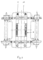
- Fig. 2 makes the position of the cylinder / piston unit 1 in the described embodiment clear.
- Coil springs instead of the previously used vertically acting Coil springs become the cylinder / piston units 1 with a minimized overall height positioned.
- the cylinder / piston units 6 with the associated ones Coil springs 9 lie horizontally below the cross member of the chassis 11 and transverse to the direction of travel of the rail vehicle and thus take no influence on the overall height of the system.
Abstract
Description
- 1.
- erste Zylinder/ Kolbeneinheit
- 2.
- Zylinder
- 3.
- Kolben
- 4.
- Kolbenstange
- 5.
- Hydraulikleitung
- 6.
- zweite Zylinder/ Kolbeneinheit
- 7.
- Zylinder
- 8.
- Kolben
- 9.
- Schraubenfeder
- 10.
- Kolbenstange
- 11.
- Fahrwerk
- 12.
- Wagenkasten
- 13.
- Druckspeicher
- 14.
- Drosselventil
Claims (4)
- Sekundärfedersystem für Fahrwerke an Niederflurfahrzeugen zur Aufnahme von zwischen dem Fahrwerk und dem Wagenkasten wirkenden Schwingungen, bestehend aus mehreren untereinander beabstandeten Sekundärfedern, die einerseits mit dem Fahrgestell und andererseits mit dem Wagenkasten verbunden sind, dadurch gekennzeichnet, dass die Sekundärfeder aus einer zwischen Wagenkasten (12) und Fahrwerk (11) angeordneten ersten vertikal einfach wirkenden Zylinder/ Kolbeneinheit (1) zur Kraftaufnahme besteht, deren Zylinder (2) mit dem Fahrwerk (11) fest verbunden ist und deren Kolben (3) mit seiner Kolbenstange (4) am Wagenkasten (12) angelenkt ist- oder umgekehrt-, wobei der Hubraum der ersten Zylinder/ Kolbeneinheit (1) über eine Hydraulikleitung (5) mit dem Hubraum einer zweiten Zylinder/Kolbeneinheit (6), die zur ersten Zylinder/ Kolbeneinheit (1) beliebig beabstandet und lageunabhängig im Schienenfahrzeug angeordnet ist, verbunden ist, und die zweite Zylinder/ Kolbeneinheit (6) mit einer Schraubenfeder (9) derart in Wirkverbindung steht, dass die Schraubenfeder (9) mit ihrem einen Ende am Zylinder (7) abgestützt ist und an ihrem anderen Ende über den Kolbens (8) der zweiten Zylinder/ Kolbeneinheit (6) beaufschlag bar ist.
- Sekundärfedersystem nach Anspruch 1, dadurch gekennzeichnet, dass parallel zur Hydraulikleitung (5) ein vorgespannter Druckspeicher (13) geschaltet ist.
- Sekundärfedersystem nach Anspruch 1 oder 2, dadurch gekennzeichnet, dass in der Hydraulikleitung (5) ein Drosselventil (14) angeordnet ist.
- Sekundärfedersystem nach mindestens einem der vorhergehenden Ansprüche 1 bis 3, dadurch gekennzeichnet, dass die Schraubenfeder (9) den Zylinder (7) der zweiten Zylinder/ Kolbeneinheit (6) mit koaxialer Wirkungsrichtung umgibt.
Applications Claiming Priority (2)
| Application Number | Priority Date | Filing Date | Title |
|---|---|---|---|
| DE10128003 | 2001-06-08 | ||
| DE10128003A DE10128003A1 (de) | 2001-06-08 | 2001-06-08 | Sekundärfedersystem für Fahrwerke an Niederflurfahrzeugen |
Publications (2)
| Publication Number | Publication Date |
|---|---|
| EP1264750A1 true EP1264750A1 (de) | 2002-12-11 |
| EP1264750B1 EP1264750B1 (de) | 2006-11-08 |
Family
ID=7687732
Family Applications (1)
| Application Number | Title | Priority Date | Filing Date |
|---|---|---|---|
| EP02012004A Expired - Lifetime EP1264750B1 (de) | 2001-06-08 | 2002-05-31 | Sekundärfedersystem für Fahrwerke an Niederflurfahrzeugen |
Country Status (4)
| Country | Link |
|---|---|
| EP (1) | EP1264750B1 (de) |
| AT (1) | ATE344751T1 (de) |
| DE (2) | DE10128003A1 (de) |
| ES (1) | ES2275775T3 (de) |
Cited By (1)
| Publication number | Priority date | Publication date | Assignee | Title |
|---|---|---|---|---|
| DE102012105310A1 (de) | 2012-06-19 | 2013-12-19 | Bombardier Transportation Gmbh | Fahrzeug mit einer Federeinrichtung mit vorgebbarer Querfedercharakteristik |
Citations (6)
| Publication number | Priority date | Publication date | Assignee | Title |
|---|---|---|---|---|
| US3287025A (en) * | 1963-07-18 | 1966-11-22 | Alfa Romeo Spa | Suspension with constant trim and frequency |
| US3889607A (en) * | 1974-07-05 | 1975-06-17 | Evans Prod Co | Car rock and roll hydraulic side bearing stabilizing arrangement |
| DE3723833A1 (de) | 1986-07-31 | 1988-02-11 | Sig Schweiz Industrieges | Radsatzfuehrung fuer schnellfahrfaehige drehgestelle von schienenfahrzeugen und verfahren zum umruesten von drehgestellen auf diese radsatzfuehrung |
| DE4238574A1 (de) | 1992-11-16 | 1994-05-19 | Abb Henschel Waggon Union | Fahrwerk für Niederflurbahnen |
| DE4243886A1 (de) * | 1992-12-23 | 1994-06-30 | Rexroth Mannesmann Gmbh | Aufhängung für einen Wagenkasten an einem Fahrgestell, insbesondere an einem Drehgestell eines schienengebundenen Fahrzeugs |
| EP1029764A2 (de) * | 1999-02-19 | 2000-08-23 | Siemens SGP Verkehrstechnik GmbH | Federung für Schienenfahrzeuge |
Family Cites Families (2)
| Publication number | Priority date | Publication date | Assignee | Title |
|---|---|---|---|---|
| DE4040047C2 (de) * | 1990-12-14 | 1996-06-27 | Rexroth Mannesmann Gmbh | Wagenkasten-Neigungssystem |
| KR0131314B1 (ko) * | 1992-06-24 | 1998-04-21 | 전성원 | 자동차의 전륜 현가장치 |
-
2001
- 2001-06-08 DE DE10128003A patent/DE10128003A1/de not_active Ceased
-
2002
- 2002-05-31 ES ES02012004T patent/ES2275775T3/es not_active Expired - Lifetime
- 2002-05-31 DE DE50208635T patent/DE50208635D1/de not_active Expired - Lifetime
- 2002-05-31 AT AT02012004T patent/ATE344751T1/de active
- 2002-05-31 EP EP02012004A patent/EP1264750B1/de not_active Expired - Lifetime
Patent Citations (6)
| Publication number | Priority date | Publication date | Assignee | Title |
|---|---|---|---|---|
| US3287025A (en) * | 1963-07-18 | 1966-11-22 | Alfa Romeo Spa | Suspension with constant trim and frequency |
| US3889607A (en) * | 1974-07-05 | 1975-06-17 | Evans Prod Co | Car rock and roll hydraulic side bearing stabilizing arrangement |
| DE3723833A1 (de) | 1986-07-31 | 1988-02-11 | Sig Schweiz Industrieges | Radsatzfuehrung fuer schnellfahrfaehige drehgestelle von schienenfahrzeugen und verfahren zum umruesten von drehgestellen auf diese radsatzfuehrung |
| DE4238574A1 (de) | 1992-11-16 | 1994-05-19 | Abb Henschel Waggon Union | Fahrwerk für Niederflurbahnen |
| DE4243886A1 (de) * | 1992-12-23 | 1994-06-30 | Rexroth Mannesmann Gmbh | Aufhängung für einen Wagenkasten an einem Fahrgestell, insbesondere an einem Drehgestell eines schienengebundenen Fahrzeugs |
| EP1029764A2 (de) * | 1999-02-19 | 2000-08-23 | Siemens SGP Verkehrstechnik GmbH | Federung für Schienenfahrzeuge |
Cited By (1)
| Publication number | Priority date | Publication date | Assignee | Title |
|---|---|---|---|---|
| DE102012105310A1 (de) | 2012-06-19 | 2013-12-19 | Bombardier Transportation Gmbh | Fahrzeug mit einer Federeinrichtung mit vorgebbarer Querfedercharakteristik |
Also Published As
| Publication number | Publication date |
|---|---|
| ES2275775T3 (es) | 2007-06-16 |
| DE50208635D1 (de) | 2006-12-21 |
| DE10128003A1 (de) | 2002-12-12 |
| EP1264750B1 (de) | 2006-11-08 |
| ATE344751T1 (de) | 2006-11-15 |
Similar Documents
| Publication | Publication Date | Title |
|---|---|---|
| DE102012110359B4 (de) | Aktives Wankstabilisierungssystem | |
| EP2804774A1 (de) | Fahrerhaus-aufhängungseinrichtung mit wankstabilisierung | |
| DE102009026503A1 (de) | Wattgestänge-Aufhängungseinrichtung mit integrierter Federung/Dämpfung | |
| DE10316497A1 (de) | Fahrwerk für ein Schienenfahrzeug mit verbesserter Querfederung | |
| EP0619212A1 (de) | Wankstütze für Schienenfahrzeuge | |
| DD271089A1 (de) | Luftfederdrehgestell, insbesondere fuer schnellauffaehige schienenfahrzeuge | |
| EP1154908B1 (de) | Achsaufhängung für starrachsen von fahrzeugen | |
| DE102014205635A1 (de) | Einzelradaufhängung sowie Hinterachse mit Einzelradaufhängungen für ein Fahrzeug und entsprechend ausgestattetes Fahrzeug | |
| EP2386454B1 (de) | Drehgestell | |
| DD141769A1 (de) | Schwingungsgeminderte fahrerkabine fuer selbstfahrende arbeitsmaschinen | |
| DE19508611A1 (de) | Federungssystem zur Verringerung der Wankbewegung eines Fahrzeugs | |
| DE19958178C1 (de) | Feder-Dämpfer-Bein | |
| DE4204783A1 (de) | Laufwerk fuer schienenfahrzeuge | |
| EP2551167A2 (de) | Lastabhängige Federanordnung | |
| EP1264750B1 (de) | Sekundärfedersystem für Fahrwerke an Niederflurfahrzeugen | |
| DE4309324C1 (de) | Einachsfahrwerk für Schienenfahrzeuge | |
| AT408642B (de) | Triebfahrzeug, insbesondere eisenbahn-hochgeschwindigkeits-triebfahrzeug | |
| DE2029329B2 (de) | Achslagerfuehrung fuer schienenfahrzeuge, insbesondere fuer drehgestell-lokomotiven | |
| DE4105350C2 (de) | Sekundärfederung für Drehgestelle von Schienenfahrzeugen | |
| DE2635637C3 (de) | Radsatzabfederung für Fahrgestelle, insbesondere Drehgestelle von schnellfahrenden Schienenfahrzeugen | |
| EP3752402A1 (de) | Fahrwerk für ein schienenfahrzeug | |
| DE449828C (de) | Stossdaempfer, insbesondere fuer Kraftfahrzeuge | |
| EP1560740B1 (de) | Federsäule für eine radsatzführung eines schienenfahrzeugs | |
| EP0122513A2 (de) | Elastische Fahrerhauslagerung eines Lastkraftwagens | |
| DE102020135041A1 (de) | Schweberahmen, Fahrzeug, Schienenanordnung und Magnetschwebebahn |
Legal Events
| Date | Code | Title | Description |
|---|---|---|---|
| PUAI | Public reference made under article 153(3) epc to a published international application that has entered the european phase |
Free format text: ORIGINAL CODE: 0009012 |
|
| AK | Designated contracting states |
Kind code of ref document: A1 Designated state(s): AT BE CH CY DE DK ES FI FR GB GR IE IT LI LU MC NL PT SE TR |
|
| AX | Request for extension of the european patent |
Free format text: AL;LT;LV;MK;RO;SI |
|
| 17P | Request for examination filed |
Effective date: 20030516 |
|
| AKX | Designation fees paid |
Designated state(s): AT BE CH CY DE DK ES FI FR GB GR IE IT LI LU MC NL PT SE TR |
|
| GRAP | Despatch of communication of intention to grant a patent |
Free format text: ORIGINAL CODE: EPIDOSNIGR1 |
|
| GRAS | Grant fee paid |
Free format text: ORIGINAL CODE: EPIDOSNIGR3 |
|
| GRAA | (expected) grant |
Free format text: ORIGINAL CODE: 0009210 |
|
| AK | Designated contracting states |
Kind code of ref document: B1 Designated state(s): AT BE CH CY DE DK ES FI FR GB GR IE IT LI LU MC NL PT SE TR |
|
| PG25 | Lapsed in a contracting state [announced via postgrant information from national office to epo] |
Ref country code: IE Free format text: LAPSE BECAUSE OF FAILURE TO SUBMIT A TRANSLATION OF THE DESCRIPTION OR TO PAY THE FEE WITHIN THE PRESCRIBED TIME-LIMIT Effective date: 20061108 Ref country code: FI Free format text: LAPSE BECAUSE OF FAILURE TO SUBMIT A TRANSLATION OF THE DESCRIPTION OR TO PAY THE FEE WITHIN THE PRESCRIBED TIME-LIMIT Effective date: 20061108 |
|
| REG | Reference to a national code |
Ref country code: GB Ref legal event code: FG4D Free format text: NOT ENGLISH |
|
| REG | Reference to a national code |
Ref country code: CH Ref legal event code: EP |
|
| REG | Reference to a national code |
Ref country code: IE Ref legal event code: FG4D Free format text: LANGUAGE OF EP DOCUMENT: GERMAN |
|
| REF | Corresponds to: |
Ref document number: 50208635 Country of ref document: DE Date of ref document: 20061221 Kind code of ref document: P |
|
| PG25 | Lapsed in a contracting state [announced via postgrant information from national office to epo] |
Ref country code: SE Free format text: LAPSE BECAUSE OF FAILURE TO SUBMIT A TRANSLATION OF THE DESCRIPTION OR TO PAY THE FEE WITHIN THE PRESCRIBED TIME-LIMIT Effective date: 20070208 Ref country code: DK Free format text: LAPSE BECAUSE OF FAILURE TO SUBMIT A TRANSLATION OF THE DESCRIPTION OR TO PAY THE FEE WITHIN THE PRESCRIBED TIME-LIMIT Effective date: 20070208 |
|
| GBT | Gb: translation of ep patent filed (gb section 77(6)(a)/1977) |
Effective date: 20070213 |
|
| PG25 | Lapsed in a contracting state [announced via postgrant information from national office to epo] |
Ref country code: PT Free format text: LAPSE BECAUSE OF FAILURE TO SUBMIT A TRANSLATION OF THE DESCRIPTION OR TO PAY THE FEE WITHIN THE PRESCRIBED TIME-LIMIT Effective date: 20070409 |
|
| ET | Fr: translation filed | ||
| REG | Reference to a national code |
Ref country code: ES Ref legal event code: FG2A Ref document number: 2275775 Country of ref document: ES Kind code of ref document: T3 |
|
| REG | Reference to a national code |
Ref country code: IE Ref legal event code: FD4D |
|
| PLBI | Opposition filed |
Free format text: ORIGINAL CODE: 0009260 |
|
| 26 | Opposition filed |
Opponent name: BOMBARDIER TRANSPORTATION GMBH Effective date: 20070806 |
|
| PLAX | Notice of opposition and request to file observation + time limit sent |
Free format text: ORIGINAL CODE: EPIDOSNOBS2 |
|
| NLR1 | Nl: opposition has been filed with the epo |
Opponent name: BOMBARDIER TRANSPORTATION GMBH |
|
| BERE | Be: lapsed |
Owner name: ALSTOM LHB G.M.B.H. Effective date: 20070531 |
|
| PLAF | Information modified related to communication of a notice of opposition and request to file observations + time limit |
Free format text: ORIGINAL CODE: EPIDOSCOBS2 |
|
| PG25 | Lapsed in a contracting state [announced via postgrant information from national office to epo] |
Ref country code: MC Free format text: LAPSE BECAUSE OF NON-PAYMENT OF DUE FEES Effective date: 20070531 |
|
| PLBB | Reply of patent proprietor to notice(s) of opposition received |
Free format text: ORIGINAL CODE: EPIDOSNOBS3 |
|
| PG25 | Lapsed in a contracting state [announced via postgrant information from national office to epo] |
Ref country code: BE Free format text: LAPSE BECAUSE OF NON-PAYMENT OF DUE FEES Effective date: 20070531 |
|
| PG25 | Lapsed in a contracting state [announced via postgrant information from national office to epo] |
Ref country code: GR Free format text: LAPSE BECAUSE OF FAILURE TO SUBMIT A TRANSLATION OF THE DESCRIPTION OR TO PAY THE FEE WITHIN THE PRESCRIBED TIME-LIMIT Effective date: 20070209 |
|
| PLCK | Communication despatched that opposition was rejected |
Free format text: ORIGINAL CODE: EPIDOSNREJ1 |
|
| APBM | Appeal reference recorded |
Free format text: ORIGINAL CODE: EPIDOSNREFNO |
|
| APBP | Date of receipt of notice of appeal recorded |
Free format text: ORIGINAL CODE: EPIDOSNNOA2O |
|
| APAH | Appeal reference modified |
Free format text: ORIGINAL CODE: EPIDOSCREFNO |
|
| APBQ | Date of receipt of statement of grounds of appeal recorded |
Free format text: ORIGINAL CODE: EPIDOSNNOA3O |
|
| RAP2 | Party data changed (patent owner data changed or rights of a patent transferred) |
Owner name: ALSTOM TRANSPORT DEUTSCHLAND GMBH |
|
| REG | Reference to a national code |
Ref country code: CH Ref legal event code: PCAR Free format text: SCHMAUDER & PARTNER AG PATENT- UND MARKENANWAELTE VSP;ZWAENGIWEG 7;8038 ZUERICH (CH) |
|
| PG25 | Lapsed in a contracting state [announced via postgrant information from national office to epo] |
Ref country code: LU Free format text: LAPSE BECAUSE OF NON-PAYMENT OF DUE FEES Effective date: 20070531 Ref country code: CY Free format text: LAPSE BECAUSE OF FAILURE TO SUBMIT A TRANSLATION OF THE DESCRIPTION OR TO PAY THE FEE WITHIN THE PRESCRIBED TIME-LIMIT Effective date: 20061108 |
|
| PG25 | Lapsed in a contracting state [announced via postgrant information from national office to epo] |
Ref country code: TR Free format text: LAPSE BECAUSE OF FAILURE TO SUBMIT A TRANSLATION OF THE DESCRIPTION OR TO PAY THE FEE WITHIN THE PRESCRIBED TIME-LIMIT Effective date: 20061108 |
|
| NLT2 | Nl: modifications (of names), taken from the european patent patent bulletin |
Owner name: ALSTOM TRANSPORT DEUTSCHLAND GMBH Effective date: 20090729 |
|
| APBU | Appeal procedure closed |
Free format text: ORIGINAL CODE: EPIDOSNNOA9O |
|
| PLBN | Opposition rejected |
Free format text: ORIGINAL CODE: 0009273 |
|
| STAA | Information on the status of an ep patent application or granted ep patent |
Free format text: STATUS: OPPOSITION REJECTED |
|
| 27O | Opposition rejected |
Effective date: 20111108 |
|
| REG | Reference to a national code |
Ref country code: DE Ref legal event code: R100 Ref document number: 50208635 Country of ref document: DE Effective date: 20111108 |
|
| REG | Reference to a national code |
Ref country code: FR Ref legal event code: PLFP Year of fee payment: 15 |
|
| REG | Reference to a national code |
Ref country code: FR Ref legal event code: PLFP Year of fee payment: 16 |
|
| REG | Reference to a national code |
Ref country code: FR Ref legal event code: PLFP Year of fee payment: 17 |
|
| REG | Reference to a national code |
Ref country code: DE Ref legal event code: R082 Ref document number: 50208635 Country of ref document: DE Representative=s name: LAVOIX MUNICH, DE |
|
| PGFP | Annual fee paid to national office [announced via postgrant information from national office to epo] |
Ref country code: NL Payment date: 20190521 Year of fee payment: 18 |
|
| PGFP | Annual fee paid to national office [announced via postgrant information from national office to epo] |
Ref country code: IT Payment date: 20190527 Year of fee payment: 18 Ref country code: DE Payment date: 20190521 Year of fee payment: 18 Ref country code: ES Payment date: 20190620 Year of fee payment: 18 |
|
| PGFP | Annual fee paid to national office [announced via postgrant information from national office to epo] |
Ref country code: FR Payment date: 20190522 Year of fee payment: 18 |
|
| PGFP | Annual fee paid to national office [announced via postgrant information from national office to epo] |
Ref country code: CH Payment date: 20190521 Year of fee payment: 18 |
|
| PGFP | Annual fee paid to national office [announced via postgrant information from national office to epo] |
Ref country code: GB Payment date: 20190521 Year of fee payment: 18 Ref country code: AT Payment date: 20190522 Year of fee payment: 18 |
|
| REG | Reference to a national code |
Ref country code: DE Ref legal event code: R119 Ref document number: 50208635 Country of ref document: DE |
|
| REG | Reference to a national code |
Ref country code: NL Ref legal event code: MM Effective date: 20200601 |
|
| REG | Reference to a national code |
Ref country code: AT Ref legal event code: MM01 Ref document number: 344751 Country of ref document: AT Kind code of ref document: T Effective date: 20200531 |
|
| PG25 | Lapsed in a contracting state [announced via postgrant information from national office to epo] |
Ref country code: AT Free format text: LAPSE BECAUSE OF NON-PAYMENT OF DUE FEES Effective date: 20200531 Ref country code: CH Free format text: LAPSE BECAUSE OF NON-PAYMENT OF DUE FEES Effective date: 20200531 Ref country code: LI Free format text: LAPSE BECAUSE OF NON-PAYMENT OF DUE FEES Effective date: 20200531 |
|
| PG25 | Lapsed in a contracting state [announced via postgrant information from national office to epo] |
Ref country code: NL Free format text: LAPSE BECAUSE OF NON-PAYMENT OF DUE FEES Effective date: 20200601 |
|
| GBPC | Gb: european patent ceased through non-payment of renewal fee |
Effective date: 20200531 |
|
| PG25 | Lapsed in a contracting state [announced via postgrant information from national office to epo] |
Ref country code: FR Free format text: LAPSE BECAUSE OF NON-PAYMENT OF DUE FEES Effective date: 20200531 Ref country code: GB Free format text: LAPSE BECAUSE OF NON-PAYMENT OF DUE FEES Effective date: 20200531 |
|
| PG25 | Lapsed in a contracting state [announced via postgrant information from national office to epo] |
Ref country code: DE Free format text: LAPSE BECAUSE OF NON-PAYMENT OF DUE FEES Effective date: 20201201 |
|
| PG25 | Lapsed in a contracting state [announced via postgrant information from national office to epo] |
Ref country code: IT Free format text: LAPSE BECAUSE OF NON-PAYMENT OF DUE FEES Effective date: 20200531 |
|
| PG25 | Lapsed in a contracting state [announced via postgrant information from national office to epo] |
Ref country code: ES Free format text: LAPSE BECAUSE OF NON-PAYMENT OF DUE FEES Effective date: 20200601 |