EP1263638B1 - Verfahren zur herstellung und befestigung eines elektromagnetventils - Google Patents
Verfahren zur herstellung und befestigung eines elektromagnetventils Download PDFInfo
- Publication number
- EP1263638B1 EP1263638B1 EP01911718A EP01911718A EP1263638B1 EP 1263638 B1 EP1263638 B1 EP 1263638B1 EP 01911718 A EP01911718 A EP 01911718A EP 01911718 A EP01911718 A EP 01911718A EP 1263638 B1 EP1263638 B1 EP 1263638B1
- Authority
- EP
- European Patent Office
- Prior art keywords
- valve
- housing
- closure member
- valve housing
- passage
- Prior art date
- Legal status (The legal status is an assumption and is not a legal conclusion. Google has not performed a legal analysis and makes no representation as to the accuracy of the status listed.)
- Expired - Lifetime
Links
- 238000000034 method Methods 0.000 title claims description 9
- 238000004519 manufacturing process Methods 0.000 title claims description 7
- 238000005520 cutting process Methods 0.000 claims description 2
- 238000001125 extrusion Methods 0.000 claims description 2
- 239000000463 material Substances 0.000 claims description 2
- 238000007493 shaping process Methods 0.000 claims description 2
- 238000003466 welding Methods 0.000 claims description 2
- 239000012530 fluid Substances 0.000 claims 3
- 238000004080 punching Methods 0.000 claims 2
- 230000005284 excitation Effects 0.000 claims 1
- 230000004907 flux Effects 0.000 description 6
- 238000007789 sealing Methods 0.000 description 6
- 230000006835 compression Effects 0.000 description 3
- 238000007906 compression Methods 0.000 description 3
- 230000009471 action Effects 0.000 description 2
- 238000010276 construction Methods 0.000 description 2
- 230000004048 modification Effects 0.000 description 2
- 238000012986 modification Methods 0.000 description 2
- 230000008569 process Effects 0.000 description 2
- 230000007704 transition Effects 0.000 description 2
- 239000012876 carrier material Substances 0.000 description 1
- 230000001419 dependent effect Effects 0.000 description 1
- 230000000694 effects Effects 0.000 description 1
- 238000003780 insertion Methods 0.000 description 1
- 230000037431 insertion Effects 0.000 description 1
- 239000002184 metal Substances 0.000 description 1
- 239000007787 solid Substances 0.000 description 1
- 239000013589 supplement Substances 0.000 description 1
- 238000003856 thermoforming Methods 0.000 description 1
Images


Classifications
-
- B—PERFORMING OPERATIONS; TRANSPORTING
- B60—VEHICLES IN GENERAL
- B60T—VEHICLE BRAKE CONTROL SYSTEMS OR PARTS THEREOF; BRAKE CONTROL SYSTEMS OR PARTS THEREOF, IN GENERAL; ARRANGEMENT OF BRAKING ELEMENTS ON VEHICLES IN GENERAL; PORTABLE DEVICES FOR PREVENTING UNWANTED MOVEMENT OF VEHICLES; VEHICLE MODIFICATIONS TO FACILITATE COOLING OF BRAKES
- B60T8/00—Arrangements for adjusting wheel-braking force to meet varying vehicular or ground-surface conditions, e.g. limiting or varying distribution of braking force
- B60T8/32—Arrangements for adjusting wheel-braking force to meet varying vehicular or ground-surface conditions, e.g. limiting or varying distribution of braking force responsive to a speed condition, e.g. acceleration or deceleration
- B60T8/34—Arrangements for adjusting wheel-braking force to meet varying vehicular or ground-surface conditions, e.g. limiting or varying distribution of braking force responsive to a speed condition, e.g. acceleration or deceleration having a fluid pressure regulator responsive to a speed condition
- B60T8/36—Arrangements for adjusting wheel-braking force to meet varying vehicular or ground-surface conditions, e.g. limiting or varying distribution of braking force responsive to a speed condition, e.g. acceleration or deceleration having a fluid pressure regulator responsive to a speed condition including a pilot valve responding to an electromagnetic force
- B60T8/3615—Electromagnetic valves specially adapted for anti-lock brake and traction control systems
- B60T8/363—Electromagnetic valves specially adapted for anti-lock brake and traction control systems in hydraulic systems
Definitions
- the invention relates to methods for producing and fastening an electromagnetic valve, in particular for slip-controlled motor vehicle brake systems, according to Preamble of claim 1.
- the two-part valve housing from one massive turned part and a valve sleeve caulked in the turned part consists.
- the turned part takes the by caulking in a valve carrier resulting press-in as well Holding forces while caulking the valve sleeve in Turned part exposed to the hydraulic pressure acting in the valve housing is dependent on the position of two with each other valve closing body coupled via a driver in certain limits is variable.
- the first valve closing body points to the connection with the driver in the transition area to a tappet section on an annular groove in which the a carrier made of a thin sheet metal part engages. That from the driver end facing away from the annular groove encompasses the solid, piston-shaped second driver and is pressed with this.
- DE19607933A describes an electromagnetic valve, whose disk-shaped magnetic flux guide by Thermoforming process is produced.
- the magnetic flux guide is on its outer circumference by means of an external caulking of the the material forming the receiving body in a housing bore attached to the receiving body.
- the sealing of the solenoid valve in the receiving body takes place between a the magnetic flux guide body and a housing stage clamped Sealing ring.
- WO96 / 15926A already describes a method for producing and fastening a valve carrier fixed solenoid valve of the specified type known, whose tubular valve housing from a disc-shaped Magnetflußleitmaschine is surrounded on its outer circumference another bell-shaped magnetic flux body is attached. Between the bell-shaped magnetic flux body and the valve carrier is for fixing the solenoid valve Pressed in clamping ring. The sealing of the solenoid valve happens in the valve carrier by means of a between the disc-shaped magnetic flux body and a ring filter arranged Seal. Located in the tubular valve housing an anchor with an auxiliary locking piece that is inside a further tubular anchor is arranged, which in Connection to a transition piece with a main locking piece is provided.
- valve sleeve valve housing 1 shows a solenoid valve in a significant enlargement with a one-piece, deep-drawing process designed as a valve sleeve valve housing 1, which is a separate attached to the outer circumference of the valve housing and receives the holding collar 2 fastened by means of laser welding, by non-cutting shaping, for example as a cold impact part is made.
- the essentially disc-shaped Retaining collar 2 is with the completed valve housing 1 in a stepped receiving bore of a block-shaped valve carrier 4 used and by means of an annular caulking 3 of the valve carrier material securely fastened and sealed.
- Above the holding collar 2 is the open one End portion of the sleeve-shaped valve housing 1 with a Plug 14 closed, which also functions as a Magnetic core takes over.
- the plug 14 also consists of a inexpensive and sufficiently precise cold-impact part to be manufactured, that is laser welded to the valve body 1 on the outer circumference is. Is located below the plug 14 a magnet armature 15, which consists of a round or polygonal profile by cold hammering or extrusion also very inexpensive is made.
- the magnet armature 15 closes under the action of a compression spring 16 in the basic valve position with the plunger-shaped extension of the magnet armature 15 attached first valve body 7 a first, in a second valve closing body 8 arranged valve passage 5.
- the first valve closing body 7 is expedient as a ball in the plunger section of the magnet armature 15 held by press fit while the second valve closing body 8 essentially as a pot-shaped deep-drawn part is carried out under the action of a return spring 17 acted upon in the direction of the first valve closing body 7 is. Due to the effect of between the stopper 14 and the magnet armature 15 arranged compression spring 16 remains however in the valve basic position shown in the illustration the bottom of the cup-shaped second valve closing body 8 provided at one in the lower end of the valve housing 1 second valve passage 6, the unlockable passage cross section is considerably larger than the unlockable opening cross-section the first valve passage 5.
- the return spring 17 is supported on a shoulder of the Step piston designed second valve closing body 8, which is preferably punched over the shoulder Pressure equalization openings 18, the above the Shoulder-lying collar on the inside wall of the valve housing 1 is performed.
- valve housing 1 For receiving and sealing the valve housing 1 in the bore step 11 is the valve housing 1 in the area of a housing stage 12 reduced in diameter and with a sealing ring 10 provided so that between the valve housing 1 and the bore level 11 no leakage flow between the Adjust the pressure medium inlet 13 and the pressure medium outlet 19 can.
- the essentially as a transverse channel in the valve carrier 4 shown pressure medium inlet 13 settles over the in Cavity 20 of the valve carrier 4 located ring filter 12th to the punched transverse bore 21 in the valve housing 1, see above that inlet-side pressure medium directly on the second valve closing body 8 is pending, as well as via the pressure equalization openings 18 arrives at the first valve body 7.
- both sleeve parts 1a, 1b are laser welded, those for securely fixing both sleeve parts 1a, 1b contributes so that overall through the overlay the wall thicknesses of both sleeve parts 1a, 1b in the sleeve covering area a rigid support structure for the valve body 1 comes about, which is the inclusion of the holding collar 2 acting caulking favored.
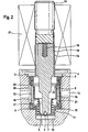
- FIG. 2 corresponds the embodiment of FIG. 1, so that Completion of the description of Fig. 2 on the Reference part for Fig. 1 is referenced.
- the solenoid valve according to FIG. 4 deviates from the previous exemplary embodiments according to FIGS. 1 to 3 a particularly clever centering of the second valve closing body 8 on the first valve closing body 7 for what the inner diameter of the second valve closing body 8 the outer diameter of the constricted tappet section on Magnet armature 15 is adapted so that the magnet armature 15 and the second valve seat body 8 associated wall sections represent corresponding sliding surfaces.
- the second valve closing body 8 is only over the plunger section turned over and concentric to the magnet armature 15 aligned.
- the precise guidance of the second valve closing body 8 happens regardless of any Dimensional tolerances of the valve housing 1, so that dimensional tolerances of valve housing 1 have no influence on the function of the second cup-shaped valve closing body 8.
- Die Valve seat surface of the second valve closing body 8 is now provided on the housing stage 9, so that the in the step 11 extending extension of the sleeve part 1b only a guiding and sealing function of the electromagnetic valve in valve carrier 4 takes over.
Landscapes
- Physics & Mathematics (AREA)
- Electromagnetism (AREA)
- Engineering & Computer Science (AREA)
- Fluid Mechanics (AREA)
- Transportation (AREA)
- Mechanical Engineering (AREA)
- Magnetically Actuated Valves (AREA)
Description
- Fig. 1
- eine erste zweckmäßige Ausführungsform der Erfindung anhand eines Längsschnitts durch ein Elektromagnetventil,
- Fig. 2
- eine Abwandlung des Gegenstandes nach Fig. 1,
- Fig. 3
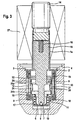
- eine Abwandlung des in Fig. 2 gezeigten Elektromagnetventils,
- Fig. 4
- basierend auf dem Ventilgehäuseaufbau des Elektromagnetventils nach den Fig. 2, 3 eine alternative Ausgestaltung zur Konstruktion und Führung des zweiten Ventilschließkörpers im Ventilgehäuse.
- 1
- Ventilgehäuse
- 2
- Haltekragen
- 3
- Außenverstemmung
- 4
- Ventilträger
- 5,6
- Ventildurchlässe
- 7
- erster Ventilschließkörper
- 8
- zweiter Ventilschließkörper
- 9
- Gehäusestufe
- 10
- Dichtring
- 11
- Bohrungsstufe
- 12
- Ringfilter
- 13
- Druckmitteleinlass
- 14
- Stopfen
- 15
- Magnetanker
- 16
- Druckfeder
- 17
- Rückstellfeder
- 18
- Druckausgleichsöffnung
- 19
- Druckmittelauslass
- 20
- Hohlraum
- 21
- Querbohrung
- 22
- Radius
- 23
- Wandschräge
- 24
- Ringraum
- 25a,
- 25b Gleitflächen
- 25
- Ventilspule
- 26
- Querbohrung
- 27
- Ventilspule
Claims (6)
- Verfahren zur Herstellung und Befestigung eines Elektromagnetventils, insbesondere für schlupfgeregelte Kraftfahrzeug-Bremsanlagen, mit einem in einem Ventilgehäuse (1) angeordneten ersten- und einem zweiten Ventilschließkörper (7, 8), die in koaxialer Anordnung im Ventilgehäuse (1) einen ersten als auch einen zweiten Ventildurchlass (5, 6) zu öffnen oder zu verschließen vermögen, mit einem in das Ventilgehäuse (1) einmündenden Druckmitteleinlassund einem Druckmittelauslasskanal (13, 19), wobei der erste Ventilschließkörper (7) abhängig von der elektromagnetischen Erregung einer Ventilspule (27) den im zweiten Ventilschließkörper (8) gelegenen ersten Ventildurchlass (5) zu öffnen oder zu verschließen vermag und wobei der zwischen dem Ventilgehäuse (1) und dem zweiten Ventilschließkörper (8) angeordnete zweite Ventildurchlass (6) ausschließlich in der Offenstellung des ersten Ventilschließkörpers (7) hydraulisch in Offenstellung schaltbar ist, gekennzeichnet durch nachfolgende Merkmale:Tiefziehen des Ventilgehäuses (1) zu einer Hülse,Herstellen eines Haltekragens (2) durch ein spanloses Umformverfahren, der am Außenumfang des Ventilgehäuses (1) mittels Laserschweißung befestigt wird,Tiefziehen des zweiten Ventilschließkörpers (8) zu einer Topfkontur, in dessen dünnwandigen Topfboden unmittelbar der erste Ventildurchlaß (5) eingestanzt oder eingeprägt wird,Herstellen des zweiten Ventildurchlasses (6) durch Stanzen oder Prägen einer Öffnung in das untere Ende des Ventilgehäuses (1), wobei der Öffnungsquerschnitt des zweiten Ventildurchlasses (6) durch das Stanzen oder Prägen gegenüber dem ersten Ventildurchlaß (5) eine größere Nennweite aufweist,Befestigen des Haltekragens (2) in einem Ventilträger (4) mittels einer Außenverstemmung (3) von Werkstoffvolumen des Ventilträgers (4).
- Verfahren nach Anspruch 1, dadurch gekennzeichnet, dass das Ventilgehäuse (1) im Bereich des zweiten Ventildurchlasses (6) eine Gehäusestufe (9) aufweist, an der am Außenumfang ein Dichtring (10) angeordnet wird, der in Längsrichtung zur Ventilrotationsachse an einer Bohrungsstufe (11) des Ventilträgers (4) angepresst wird sowie in Querrichtung zur Ventilrotationsachse von einem Ringfilter (12) begrenzt wird, der sich den Druckmitteleinlass (13) überdeckend zwischen dem Ventilgehäuse (1) und der Innenwandung des Ventilträgers (4) in einem Hohlraum (20) bis zum Haltekragen (2) erstreckt.
- Verfahren nach einem der vorhergehenden Ansprüche, dadurch gekennzeichnet, dass das Ventilgehäuse (1) einteilig ausgeführt wird, dessen vom zweiten Ventildurchlass (6) abgewandtes Ende von einem als Magnetkern wirksamen Stopfen (14) verschlossen wird, der als Kaltschlag- bzw. Fließpressteil ausgebildet wird.
- Verfahren nach Anspruch 1, dadurch gekennzeichnet, dass der Haltekragen (2) durch ein Kaltschlagteil gebildet wird.
- Verfahren nach einem der vorhergehenden Ansprüche 1 bis 3, dadurch gekennzeichnet, dass das Ventilgehäuse (1) aus zwei abschnittsweise ineinander eingefügte Hülsenteile (1a, 1b) gebildet wird, wovon das äußere Hülsenteil (1b) im Tiefziehverfahren zu einem Gehäusetopf ausgebildet wird, dessen abgekröpfter Rand den Haltekragen (2) bildet.
- Verfahren nach Anspruch 1, dadurch gekennzeichnet, dass der zweite Ventilschließkörper (8) mit seiner Innenwandung an einem den ersten Ventilschließkörper (7) aufnehmenden Stößelabschnitt eines Magnetankers (15) zentriert wird, der aus einem Kaltschlagteil hergestellt wird.
Applications Claiming Priority (3)
| Application Number | Priority Date | Filing Date | Title |
|---|---|---|---|
| DE10010734 | 2000-03-04 | ||
| DE10010734A DE10010734A1 (de) | 2000-03-04 | 2000-03-04 | Elektromagnetventil, insbesondere für schlupfgeregelte Kraftfahrzeugbremsanlagen |
| PCT/EP2001/002351 WO2001066396A1 (de) | 2000-03-04 | 2001-03-02 | Elektromagnetventil, insbesondere für schlupfgeregelte kraftfahrzeugbremsanlagen |
Publications (2)
| Publication Number | Publication Date |
|---|---|
| EP1263638A1 EP1263638A1 (de) | 2002-12-11 |
| EP1263638B1 true EP1263638B1 (de) | 2004-02-04 |
Family
ID=7633595
Family Applications (1)
| Application Number | Title | Priority Date | Filing Date |
|---|---|---|---|
| EP01911718A Expired - Lifetime EP1263638B1 (de) | 2000-03-04 | 2001-03-02 | Verfahren zur herstellung und befestigung eines elektromagnetventils |
Country Status (3)
| Country | Link |
|---|---|
| EP (1) | EP1263638B1 (de) |
| DE (2) | DE10010734A1 (de) |
| WO (1) | WO2001066396A1 (de) |
Cited By (1)
| Publication number | Priority date | Publication date | Assignee | Title |
|---|---|---|---|---|
| KR100908182B1 (ko) | 2008-05-16 | 2009-07-16 | 현대모비스 주식회사 | 짧은 축 길이를 갖는 솔레노이드 밸브 |
Families Citing this family (23)
| Publication number | Priority date | Publication date | Assignee | Title |
|---|---|---|---|---|
| JP3716219B2 (ja) * | 2001-08-21 | 2005-11-16 | マンド コーポレーション | ブレーキシステム用ソレノイドバルブ |
| DE10200979A1 (de) * | 2002-01-12 | 2003-08-07 | Danfoss As | Ventilanordnung zum Einsetzen in Vakuumanlagen |
| JP4537074B2 (ja) | 2002-04-26 | 2010-09-01 | コンチネンタル・テベス・アーゲー・ウント・コンパニー・オーハーゲー | 特にスリップ調整自動車ブレーキシステム用の電磁弁 |
| WO2004024338A2 (fr) | 2002-09-13 | 2004-03-25 | Sames Technologies | Bol de pulverisation, dispositif de projection incorporant un tel bol et installation de projection incorporant un tel dispositif |
| FR2852868B1 (fr) | 2003-03-27 | 2005-04-29 | Sames Technologies | Bol de pulverisation, dispositif de projection incorporant un tel bol et installation de projection incorporant un tel dispositif |
| WO2004055420A2 (de) * | 2002-12-13 | 2004-07-01 | Continental Teves Ag & Co. Ohg | Elektromagnetventil |
| DE20308972U1 (de) * | 2003-06-10 | 2003-08-21 | Bürkert Werke GmbH & Co KG, 74653 Ingelfingen | Kleinventil in Blechbauweise |
| EP1690149A1 (de) * | 2003-11-29 | 2006-08-16 | Continental Teves AG & Co. oHG | Druckregelventil |
| DE102005014100B4 (de) * | 2004-07-15 | 2014-01-02 | Continental Teves Ag & Co. Ohg | Elektromagnetventil, insbesondere für schlupfgeregelte Kraftfahrzeugbremsanlagen |
| DE102005034985A1 (de) * | 2005-02-02 | 2006-08-03 | Continental Teves Ag & Co. Ohg | Verschlussvorrichtung |
| DE102006013660A1 (de) | 2006-01-11 | 2007-07-12 | Continental Teves Ag & Co. Ohg | Elektromagnetventil |
| DE102007026358B4 (de) | 2007-01-10 | 2019-07-25 | Continental Teves Ag & Co. Ohg | Elektromagnetventil, insbesondere für schlupfgeregelte Kraftfahrzeugbremsanlagen |
| DE102008001864A1 (de) * | 2008-05-19 | 2009-11-26 | Robert Bosch Gmbh | Magnetventil |
| DE102009060729A1 (de) | 2009-12-29 | 2011-07-14 | Robert Bosch GmbH, 70469 | Ventilanordnung |
| US8985549B2 (en) * | 2010-02-03 | 2015-03-24 | Kelsey-Hayes Company | Electromagnetic valve |
| DE102011080176A1 (de) | 2010-09-21 | 2012-03-22 | Continental Teves Ag & Co. Ohg | Elektromagnetventil, insbesondere für schlupfgeregelte Kraftfahrzeugbremsanlagen |
| DE102011009059A1 (de) * | 2011-01-20 | 2012-07-26 | Ipgate Ag | Betätigungseinrichtung, insbesondere für Fahrzeugbremsen |
| DE102011004350A1 (de) * | 2011-02-18 | 2012-08-23 | Continental Teves Ag & Co. Ohg | Elektromagnetventil, insbesondere für schlupfgeregelte Kraftfahrzeugbremsanlagen |
| DE102011076556A1 (de) * | 2011-05-26 | 2012-11-29 | Continental Teves Ag & Co. Ohg | Elektromagnetventil, insbesondere für schlupfgeregelte Kraftfahrzeugbremsanlagen |
| JP5702316B2 (ja) * | 2012-02-10 | 2015-04-15 | 株式会社鷺宮製作所 | 膨張弁 |
| DE102013224080B4 (de) * | 2013-11-26 | 2025-03-13 | Continental Automotive Technologies GmbH | Elektromagnetventil, insbesondere für schlupfgeregelte Kraftfahrzeugbremsanlagen |
| DE102017210351A1 (de) * | 2017-06-21 | 2018-12-27 | Robert Bosch Gmbh | Proportionalventil zum Steuern eines gasförmigen Mediums und Brennstoffzellenanordnung |
| EP3628852B8 (de) * | 2018-09-28 | 2021-12-22 | Vitesco Technologies GmbH | Ventil und verfahren zum herstellen eines ventils |
Family Cites Families (11)
| Publication number | Priority date | Publication date | Assignee | Title |
|---|---|---|---|---|
| DE4332538A1 (de) * | 1993-09-24 | 1995-03-30 | Bosch Gmbh Robert | Hydraulikaggregat für schlupfgeregelte Bremsanlagen von Kraftfahrzeugen |
| JP3147684B2 (ja) * | 1994-02-15 | 2001-03-19 | トヨタ自動車株式会社 | 電磁弁の製造方法 |
| US5681097A (en) * | 1994-02-18 | 1997-10-28 | Kelsey-Hayes Company | Hydraulic control unit for vehicular anti-lock brake and traction control systems |
| EP0746485B1 (de) * | 1994-11-24 | 2000-03-01 | Robert Bosch Gmbh | Elektromagnetisch steuerbare ventilanordnung |
| DE19529724A1 (de) * | 1995-08-12 | 1997-02-13 | Teves Gmbh Alfred | Elektromagnetventil, insbesondere für hydraulische Kraftfahrzeugbremsanlagen mit Radschlupfregelung |
| DE19607933B4 (de) * | 1996-01-31 | 2005-12-22 | Continental Teves Ag & Co. Ohg | Elektromagnetventil |
| DE19621229A1 (de) * | 1996-05-25 | 1997-11-27 | Bosch Gmbh Robert | Ventilblock mit wenigstens einem elektromagnetisch steuerbaren Ventil insbesondere für eine hydraulische Fahrzeugbremsanlage |
| DE19626304A1 (de) * | 1996-07-01 | 1998-01-08 | Teves Gmbh Alfred | Hydraulische Bremsanlage mit einer Vorladeeinrichtung |
| DE19635691A1 (de) * | 1996-09-03 | 1998-03-05 | Bosch Gmbh Robert | Magnetventil für eine schlupfgeregelte, hydraulische Fahrzeugbremsanlage |
| DE19807130A1 (de) * | 1998-02-20 | 1999-08-26 | Bosch Gmbh Robert | Magnetventil für eine schlupfgeregelte, hydraulische Fahrzeugbremsanlage |
| WO2001000473A1 (de) * | 1999-06-23 | 2001-01-04 | Continental Teves Ag & Co. Ohg | Elektromagnetventil, insbesondere für hydraulische bremsanlagen mit schlupfregelung |
-
2000
- 2000-03-04 DE DE10010734A patent/DE10010734A1/de not_active Withdrawn
-
2001
- 2001-03-02 DE DE50101438T patent/DE50101438D1/de not_active Expired - Lifetime
- 2001-03-02 EP EP01911718A patent/EP1263638B1/de not_active Expired - Lifetime
- 2001-03-02 WO PCT/EP2001/002351 patent/WO2001066396A1/de not_active Ceased
Cited By (1)
| Publication number | Priority date | Publication date | Assignee | Title |
|---|---|---|---|---|
| KR100908182B1 (ko) | 2008-05-16 | 2009-07-16 | 현대모비스 주식회사 | 짧은 축 길이를 갖는 솔레노이드 밸브 |
Also Published As
| Publication number | Publication date |
|---|---|
| DE10010734A1 (de) | 2001-09-06 |
| EP1263638A1 (de) | 2002-12-11 |
| WO2001066396A1 (de) | 2001-09-13 |
| DE50101438D1 (de) | 2004-03-11 |
Similar Documents
| Publication | Publication Date | Title |
|---|---|---|
| EP1263638A1 (de) | Elektromagnetventil, insbesondere für schlupfgeregelte kraftfahrzeugbremsanlagen | |
| EP0971833B1 (de) | Magnetventil mit integriertem rückschlagventil | |
| DE19951665A1 (de) | Elektromagnetventil, insbesondere für hydraulische Bremsanlagen mit Schlupfregelung | |
| DE19531010B4 (de) | Magnetventil, insbesondere für eine schlupfgeregelte, hydraulische Bremsanlage für Kraftfahrzeuge | |
| DE19635691A1 (de) | Magnetventil für eine schlupfgeregelte, hydraulische Fahrzeugbremsanlage | |
| WO2001000473A1 (de) | Elektromagnetventil, insbesondere für hydraulische bremsanlagen mit schlupfregelung | |
| DE10200915A1 (de) | Elektromagnetventil für Fahrzeugbremsanlagen | |
| WO2000018628A1 (de) | Magnetventil, insbesondere für eine schlupfgeregelte, hydraulische fahrzeugbremsanlage | |
| WO2013072215A1 (de) | Elektromagnetventil, insbesondere für schlupfgeregelte kraftfahrzeugbremsanlagen | |
| DE10047399A1 (de) | Elektromagnetventil, insbesondere für hydraulische Bremsanlagen mit Schlupfregelung | |
| DE102020206644A1 (de) | Elektromagnetventil, insbesondere für schlupfgeregelte Kraftfahrzeugbremsanlagen | |
| DE102008020855A1 (de) | Elektromagnetventil, insbesondere für schlupfgeregelte Kraftfahrzeugbremsanlagen | |
| DE19910207A1 (de) | Ventil, insbesondere für schlupfgeregelte hydraulische Bremsanlagen von Kraftfahrzeugen | |
| WO2012156341A1 (de) | Elektromagnetventil, insbesondere für schlupfgeregelte kraftfahrzeugbremsanlagen | |
| DE10064169A1 (de) | Elektromagnetventil | |
| WO2004055420A2 (de) | Elektromagnetventil | |
| DE102007026358B4 (de) | Elektromagnetventil, insbesondere für schlupfgeregelte Kraftfahrzeugbremsanlagen | |
| DE10046046A1 (de) | Elektromagnetventil | |
| WO1996029219A1 (de) | Elektromagnetventil mit druckbegrenzungsfunktion, insbesondere für hydraulische kraftfahrzeug-bremsanlagen mit schlupfregelung und/oder automatischem bremseneingriff zur fahrdynamikregelung | |
| DE19531007A1 (de) | Magnetventil, insbesondere für eine schlupfgeregelte, hydraulische Bremsanlage für Kraftfahrzeuge | |
| EP1501712B1 (de) | Elektromagnetventil, insbesondere für schlupfgeregelte kraftfahrzeugbremsanlagen | |
| DE102012215556A1 (de) | Elektromagnetventil, insbesondere für schlupfgeregelte Kraftfahrzeugbremsanlagen | |
| DE10205854A1 (de) | Elektromagnetventil, insbesondere für hydraulische Bremsanlagen | |
| DE102018220673A1 (de) | Elektromagnetventil, insbesondere für schlupfgeregelte Kraftfahrzeugbremsanlagen | |
| DE10141134A1 (de) | Elektromagnetventil, insbesondere für hydraulische Bremsanlagen mit Schlupfregelung |
Legal Events
| Date | Code | Title | Description |
|---|---|---|---|
| PUAI | Public reference made under article 153(3) epc to a published international application that has entered the european phase |
Free format text: ORIGINAL CODE: 0009012 |
|
| 17P | Request for examination filed |
Effective date: 20021004 |
|
| AK | Designated contracting states |
Kind code of ref document: A1 Designated state(s): AT BE CH CY DE DK ES FI FR GB GR IE IT LI LU MC NL PT SE TR |
|
| 17Q | First examination report despatched |
Effective date: 20030210 |
|
| GRAP | Despatch of communication of intention to grant a patent |
Free format text: ORIGINAL CODE: EPIDOSNIGR1 |
|
| RTI1 | Title (correction) |
Free format text: METHOD FOR MANUFACTURING AND MOUNTING A SOLENOID VALVE |
|
| RTI1 | Title (correction) |
Free format text: METHOD FOR MANUFACTURING AND MOUNTING A SOLENOID VALVE |
|
| GRAS | Grant fee paid |
Free format text: ORIGINAL CODE: EPIDOSNIGR3 |
|
| GRAA | (expected) grant |
Free format text: ORIGINAL CODE: 0009210 |
|
| AK | Designated contracting states |
Kind code of ref document: B1 Designated state(s): DE FR |
|
| REG | Reference to a national code |
Ref country code: IE Ref legal event code: FG4D Free format text: GERMAN |
|
| REF | Corresponds to: |
Ref document number: 50101438 Country of ref document: DE Date of ref document: 20040311 Kind code of ref document: P |
|
| REG | Reference to a national code |
Ref country code: IE Ref legal event code: FD4D |
|
| ET | Fr: translation filed | ||
| PLBE | No opposition filed within time limit |
Free format text: ORIGINAL CODE: 0009261 |
|
| STAA | Information on the status of an ep patent application or granted ep patent |
Free format text: STATUS: NO OPPOSITION FILED WITHIN TIME LIMIT |
|
| 26N | No opposition filed |
Effective date: 20041105 |
|
| PGFP | Annual fee paid to national office [announced via postgrant information from national office to epo] |
Ref country code: DE Payment date: 20130331 Year of fee payment: 13 |
|
| PGFP | Annual fee paid to national office [announced via postgrant information from national office to epo] |
Ref country code: FR Payment date: 20130419 Year of fee payment: 13 |
|
| REG | Reference to a national code |
Ref country code: DE Ref legal event code: R231 Ref document number: 50101438 Country of ref document: DE |
|
| PG25 | Lapsed in a contracting state [announced via postgrant information from national office to epo] |
Ref country code: DE Free format text: LAPSE BECAUSE OF THE APPLICANT RENOUNCES Effective date: 20131018 |
|
| REG | Reference to a national code |
Ref country code: FR Ref legal event code: ST Effective date: 20141128 |
|
| PG25 | Lapsed in a contracting state [announced via postgrant information from national office to epo] |
Ref country code: FR Free format text: LAPSE BECAUSE OF NON-PAYMENT OF DUE FEES Effective date: 20140331 |