EP0746485B1 - Elektromagnetisch steuerbare ventilanordnung - Google Patents
Elektromagnetisch steuerbare ventilanordnung Download PDFInfo
- Publication number
- EP0746485B1 EP0746485B1 EP95936432A EP95936432A EP0746485B1 EP 0746485 B1 EP0746485 B1 EP 0746485B1 EP 95936432 A EP95936432 A EP 95936432A EP 95936432 A EP95936432 A EP 95936432A EP 0746485 B1 EP0746485 B1 EP 0746485B1
- Authority
- EP
- European Patent Office
- Prior art keywords
- closure part
- armature
- auxiliary
- main
- valve
- Prior art date
- Legal status (The legal status is an assumption and is not a legal conclusion. Google has not performed a legal analysis and makes no representation as to the accuracy of the status listed.)
- Expired - Lifetime
Links
- 230000007704 transition Effects 0.000 claims description 16
- 239000000696 magnetic material Substances 0.000 claims description 3
- 239000000463 material Substances 0.000 claims 1
- 230000008901 benefit Effects 0.000 description 4
- 230000004907 flux Effects 0.000 description 4
- 238000004519 manufacturing process Methods 0.000 description 3
- 238000011161 development Methods 0.000 description 2
- 230000018109 developmental process Effects 0.000 description 2
- 239000012528 membrane Substances 0.000 description 2
- 238000000034 method Methods 0.000 description 2
- 238000003825 pressing Methods 0.000 description 2
- 230000008569 process Effects 0.000 description 2
- 230000009471 action Effects 0.000 description 1
- 230000008859 change Effects 0.000 description 1
- 230000001419 dependent effect Effects 0.000 description 1
- 230000000994 depressogenic effect Effects 0.000 description 1
- 238000010586 diagram Methods 0.000 description 1
- 238000006073 displacement reaction Methods 0.000 description 1
- 230000000694 effects Effects 0.000 description 1
- 230000002996 emotional effect Effects 0.000 description 1
- 238000005516 engineering process Methods 0.000 description 1
- 239000012530 fluid Substances 0.000 description 1
- 230000009467 reduction Effects 0.000 description 1
- 238000011144 upstream manufacturing Methods 0.000 description 1
- 238000003466 welding Methods 0.000 description 1
Images
Classifications
-
- F—MECHANICAL ENGINEERING; LIGHTING; HEATING; WEAPONS; BLASTING
- F16—ENGINEERING ELEMENTS AND UNITS; GENERAL MEASURES FOR PRODUCING AND MAINTAINING EFFECTIVE FUNCTIONING OF MACHINES OR INSTALLATIONS; THERMAL INSULATION IN GENERAL
- F16K—VALVES; TAPS; COCKS; ACTUATING-FLOATS; DEVICES FOR VENTING OR AERATING
- F16K31/00—Actuating devices; Operating means; Releasing devices
- F16K31/02—Actuating devices; Operating means; Releasing devices electric; magnetic
- F16K31/06—Actuating devices; Operating means; Releasing devices electric; magnetic using a magnet, e.g. diaphragm valves, cutting off by means of a liquid
- F16K31/0686—Braking, pressure equilibration, shock absorbing
- F16K31/0693—Pressure equilibration of the armature
-
- B—PERFORMING OPERATIONS; TRANSPORTING
- B60—VEHICLES IN GENERAL
- B60T—VEHICLE BRAKE CONTROL SYSTEMS OR PARTS THEREOF; BRAKE CONTROL SYSTEMS OR PARTS THEREOF, IN GENERAL; ARRANGEMENT OF BRAKING ELEMENTS ON VEHICLES IN GENERAL; PORTABLE DEVICES FOR PREVENTING UNWANTED MOVEMENT OF VEHICLES; VEHICLE MODIFICATIONS TO FACILITATE COOLING OF BRAKES
- B60T15/00—Construction arrangement, or operation of valves incorporated in power brake systems and not covered by groups B60T11/00 or B60T13/00
- B60T15/02—Application and release valves
- B60T15/025—Electrically controlled valves
- B60T15/028—Electrically controlled valves in hydraulic systems
-
- B—PERFORMING OPERATIONS; TRANSPORTING
- B60—VEHICLES IN GENERAL
- B60T—VEHICLE BRAKE CONTROL SYSTEMS OR PARTS THEREOF; BRAKE CONTROL SYSTEMS OR PARTS THEREOF, IN GENERAL; ARRANGEMENT OF BRAKING ELEMENTS ON VEHICLES IN GENERAL; PORTABLE DEVICES FOR PREVENTING UNWANTED MOVEMENT OF VEHICLES; VEHICLE MODIFICATIONS TO FACILITATE COOLING OF BRAKES
- B60T8/00—Arrangements for adjusting wheel-braking force to meet varying vehicular or ground-surface conditions, e.g. limiting or varying distribution of braking force
- B60T8/32—Arrangements for adjusting wheel-braking force to meet varying vehicular or ground-surface conditions, e.g. limiting or varying distribution of braking force responsive to a speed condition, e.g. acceleration or deceleration
- B60T8/34—Arrangements for adjusting wheel-braking force to meet varying vehicular or ground-surface conditions, e.g. limiting or varying distribution of braking force responsive to a speed condition, e.g. acceleration or deceleration having a fluid pressure regulator responsive to a speed condition
- B60T8/36—Arrangements for adjusting wheel-braking force to meet varying vehicular or ground-surface conditions, e.g. limiting or varying distribution of braking force responsive to a speed condition, e.g. acceleration or deceleration having a fluid pressure regulator responsive to a speed condition including a pilot valve responding to an electromagnetic force
- B60T8/3615—Electromagnetic valves specially adapted for anti-lock brake and traction control systems
- B60T8/363—Electromagnetic valves specially adapted for anti-lock brake and traction control systems in hydraulic systems
- B60T8/365—Electromagnetic valves specially adapted for anti-lock brake and traction control systems in hydraulic systems combining a plurality of functions in one unit, e.g. pressure relief
-
- B—PERFORMING OPERATIONS; TRANSPORTING
- B60—VEHICLES IN GENERAL
- B60T—VEHICLE BRAKE CONTROL SYSTEMS OR PARTS THEREOF; BRAKE CONTROL SYSTEMS OR PARTS THEREOF, IN GENERAL; ARRANGEMENT OF BRAKING ELEMENTS ON VEHICLES IN GENERAL; PORTABLE DEVICES FOR PREVENTING UNWANTED MOVEMENT OF VEHICLES; VEHICLE MODIFICATIONS TO FACILITATE COOLING OF BRAKES
- B60T8/00—Arrangements for adjusting wheel-braking force to meet varying vehicular or ground-surface conditions, e.g. limiting or varying distribution of braking force
- B60T8/32—Arrangements for adjusting wheel-braking force to meet varying vehicular or ground-surface conditions, e.g. limiting or varying distribution of braking force responsive to a speed condition, e.g. acceleration or deceleration
- B60T8/34—Arrangements for adjusting wheel-braking force to meet varying vehicular or ground-surface conditions, e.g. limiting or varying distribution of braking force responsive to a speed condition, e.g. acceleration or deceleration having a fluid pressure regulator responsive to a speed condition
- B60T8/48—Arrangements for adjusting wheel-braking force to meet varying vehicular or ground-surface conditions, e.g. limiting or varying distribution of braking force responsive to a speed condition, e.g. acceleration or deceleration having a fluid pressure regulator responsive to a speed condition connecting the brake actuator to an alternative or additional source of fluid pressure, e.g. traction control systems
- B60T8/4809—Traction control, stability control, using both the wheel brakes and other automatic braking systems
- B60T8/4827—Traction control, stability control, using both the wheel brakes and other automatic braking systems in hydraulic brake systems
- B60T8/4863—Traction control, stability control, using both the wheel brakes and other automatic braking systems in hydraulic brake systems closed systems
- B60T8/4872—Traction control, stability control, using both the wheel brakes and other automatic braking systems in hydraulic brake systems closed systems pump-back systems
-
- B—PERFORMING OPERATIONS; TRANSPORTING
- B60—VEHICLES IN GENERAL
- B60T—VEHICLE BRAKE CONTROL SYSTEMS OR PARTS THEREOF; BRAKE CONTROL SYSTEMS OR PARTS THEREOF, IN GENERAL; ARRANGEMENT OF BRAKING ELEMENTS ON VEHICLES IN GENERAL; PORTABLE DEVICES FOR PREVENTING UNWANTED MOVEMENT OF VEHICLES; VEHICLE MODIFICATIONS TO FACILITATE COOLING OF BRAKES
- B60T8/00—Arrangements for adjusting wheel-braking force to meet varying vehicular or ground-surface conditions, e.g. limiting or varying distribution of braking force
- B60T8/32—Arrangements for adjusting wheel-braking force to meet varying vehicular or ground-surface conditions, e.g. limiting or varying distribution of braking force responsive to a speed condition, e.g. acceleration or deceleration
- B60T8/34—Arrangements for adjusting wheel-braking force to meet varying vehicular or ground-surface conditions, e.g. limiting or varying distribution of braking force responsive to a speed condition, e.g. acceleration or deceleration having a fluid pressure regulator responsive to a speed condition
- B60T8/50—Arrangements for adjusting wheel-braking force to meet varying vehicular or ground-surface conditions, e.g. limiting or varying distribution of braking force responsive to a speed condition, e.g. acceleration or deceleration having a fluid pressure regulator responsive to a speed condition having means for controlling the rate at which pressure is reapplied to or released from the brake
- B60T8/5018—Pressure reapplication using restrictions
- B60T8/5025—Pressure reapplication using restrictions in hydraulic brake systems
-
- B—PERFORMING OPERATIONS; TRANSPORTING
- B60—VEHICLES IN GENERAL
- B60T—VEHICLE BRAKE CONTROL SYSTEMS OR PARTS THEREOF; BRAKE CONTROL SYSTEMS OR PARTS THEREOF, IN GENERAL; ARRANGEMENT OF BRAKING ELEMENTS ON VEHICLES IN GENERAL; PORTABLE DEVICES FOR PREVENTING UNWANTED MOVEMENT OF VEHICLES; VEHICLE MODIFICATIONS TO FACILITATE COOLING OF BRAKES
- B60T8/00—Arrangements for adjusting wheel-braking force to meet varying vehicular or ground-surface conditions, e.g. limiting or varying distribution of braking force
- B60T8/32—Arrangements for adjusting wheel-braking force to meet varying vehicular or ground-surface conditions, e.g. limiting or varying distribution of braking force responsive to a speed condition, e.g. acceleration or deceleration
- B60T8/34—Arrangements for adjusting wheel-braking force to meet varying vehicular or ground-surface conditions, e.g. limiting or varying distribution of braking force responsive to a speed condition, e.g. acceleration or deceleration having a fluid pressure regulator responsive to a speed condition
- B60T8/50—Arrangements for adjusting wheel-braking force to meet varying vehicular or ground-surface conditions, e.g. limiting or varying distribution of braking force responsive to a speed condition, e.g. acceleration or deceleration having a fluid pressure regulator responsive to a speed condition having means for controlling the rate at which pressure is reapplied to or released from the brake
- B60T8/5087—Pressure release using restrictions
- B60T8/5093—Pressure release using restrictions in hydraulic brake systems
-
- F—MECHANICAL ENGINEERING; LIGHTING; HEATING; WEAPONS; BLASTING
- F16—ENGINEERING ELEMENTS AND UNITS; GENERAL MEASURES FOR PRODUCING AND MAINTAINING EFFECTIVE FUNCTIONING OF MACHINES OR INSTALLATIONS; THERMAL INSULATION IN GENERAL
- F16K—VALVES; TAPS; COCKS; ACTUATING-FLOATS; DEVICES FOR VENTING OR AERATING
- F16K39/00—Devices for relieving the pressure on the sealing faces
- F16K39/02—Devices for relieving the pressure on the sealing faces for lift valves
- F16K39/024—Devices for relieving the pressure on the sealing faces for lift valves using an auxiliary valve on the main valve
-
- Y—GENERAL TAGGING OF NEW TECHNOLOGICAL DEVELOPMENTS; GENERAL TAGGING OF CROSS-SECTIONAL TECHNOLOGIES SPANNING OVER SEVERAL SECTIONS OF THE IPC; TECHNICAL SUBJECTS COVERED BY FORMER USPC CROSS-REFERENCE ART COLLECTIONS [XRACs] AND DIGESTS
- Y10—TECHNICAL SUBJECTS COVERED BY FORMER USPC
- Y10T—TECHNICAL SUBJECTS COVERED BY FORMER US CLASSIFICATION
- Y10T137/00—Fluid handling
- Y10T137/8593—Systems
- Y10T137/87169—Supply and exhaust
- Y10T137/87217—Motor
Definitions
- the invention is based on an electromagnetic controllable valve arrangement according to the preamble of claim 1.
- the publication DE 42 13 740 A1 is a hydraulic one Vehicle brake system with an anti-lock device known who is trained to a Traction control device for four drive wheels and for accelerated application of brake shoes at the beginning of a Traction control operation.
- Brake pressure for the Traction control system deliver to the anti-lock device belonging self-priming return pumps, which are characterized by Electromagnetically openable 2/2-way valves, the relative have large passage cross sections, from one Prime the master cylinder with pressure medium.
- Two auxiliary pumps are provided to apply the brake shoes.
- the publication DE 42 32 311 C1 is a hydraulic one Vehicle brake system known using a Anti-lock device is further developed for Side slip control of vehicle wheels when driving through a curve by automatic braking.
- Valve arrangements are known in general hydraulics, which consists of a main valve and an auxiliary valve, which for hydraulic control of the main valve is used.
- Such a valve arrangement essentially consists of a housing, a Main valve with one main valve seat and one Main valve plug and an auxiliary valve with one Auxiliary valve seat on the main closure piece and one of these pulling through and starting from the auxiliary valve seat Control passage and with an auxiliary closure piece and with a spring loading the auxiliary closure piece, with a movable anchor for moving the auxiliary closure piece away from the auxiliary valve seat and thus the closure piece and with another movable element that is relative to the anchor is movable and magnetically effective.
- a disadvantage of this Valve arrangement is that between the Main closure piece and the housing extends a membrane, which endangers under hydraulic pressure with high pressure and that when you open the main valve Main locking piece the anchor assembly, consisting of the Anchor and the other movable element to move Has. Because the displacement force is dependent on you Pressure difference between both sides of the membrane and because such a pressure difference when opening the main valve the main valve opens slowly.
- valve assembly according to the invention with the characteristic Features of claim 1 has the advantage that on the one hand Auxiliary lock piece can be quickly accelerated Generate hydraulic assistant for opening the Main valve, and that from the opening of the main valve, the main plug can be accelerated from its anchor, if the anchor of the auxiliary closure piece already has a stroke has traveled. Because the valve assembly according to the invention is designed so that the longest stroke of an anchor is the one who is meant to open the auxiliary valve the associated electromagnet can be relatively small and light be trained and is easily accommodated within the Anti-lock device.
- the characterizing features of claim 15 result in a advantageous combination with a hydraulic Vehicle brake system that can be set up for automatic Braking, for example, for the purpose of side slip control of vehicle wheels by braking and / or Traction control on drivable wheels by automatic braking.
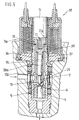
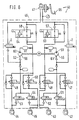
- Valve arrangement and a hydraulic vehicle brake system with the valve assembly according to the invention are in the Drawing shown and described in more detail below. It show Figures 1 to 5 five Valve arrangements in longitudinal section and Figure 6 the circuit diagram of a hydraulic vehicle brake system, in which the valve assembly according to the invention is installed.
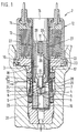
- the valve arrangement 2 has a housing 3, a main valve 4 with a main valve seat 5 and with a Main closure piece 6, an auxiliary valve 7 with a Auxiliary valve seat 8, with a control passage 9, with a Auxiliary closure piece 10 and with a spring 11 and one Electromagnet 12 with a coil 13 with a relative to Coil 13 stationary pole core 14, with a magnetic flux guide 15 around the coil 13 and with one to the magnetic flux guide 15 subsequent further magnetic flux guide body 16, the leads to the housing 3, with an anchor 17 and another Anchor 18
- the coil 13, the pole core 14 and the magnetic flux guide 15 and 16 and also the housing 3 are taken from one Electromagnetically actuated valve according to the document GB 2 263 741 A.
- the invention can thus also be recognized directed, from already created and proven components To make use of. It also follows that the Invention is directed to a since then Available space size.
- the main valve seat 5 is comparable to that known valve in a valve seat body 19, which is held in the tubular housing 3. At the the other end of the tubular housing 3 is as in the state the technology, the pole core 14 hydraulically sealed.
- the spring 11 is based on the Polkern 14 from and extends into a recess 20, the is incorporated into the anchor 18.
- the anchor 18 is cylindrical and combined with a plunger 21 which the auxiliary closure piece 10 connects.
- the anchor 18, the plunger 21 and that Auxiliary closure piece 10 may be formed in one piece by Pressing in a die.
- the armature 18 has a diameter that is smaller than that Diameter of the pole core 14.
- the other anchor 17 is, according to Art a tube so that it is left with a radial distance 22, that is, an air gap, the armature 18th is able to record.
- a further radial distance 23 for a further air gap, whereby the armature 17 relative to the Housing 3 and the armature 18 movable relative to the armature 17 is.
- the essentially tubular anchor 17 is included tubular transition 24 with which the main closure piece 6 is firmly connected.
- the main closure piece 6, the tubular one Transition 24 and the tubular anchor 17 can also be made in one piece by pressing.
- In the tubular Transition 24 to the plunger 21 is in essential ring-like chamber 25 to the auxiliary valve seat 8th leads.
- the armature 17 has an anchor face 26 which is ring-shaped and opposite the pole core 14. From this ring-like Anchor end face 26 extends in the longitudinal direction of anchor 17 For example, two longitudinal grooves 27, which in the area of tubular transition 24 open.
- the armature 18 also has an anchor end face 28 which corresponds to the round cross section of the Anchor 18 accordingly and also because of the recess 20 is designed as an annular surface.
- the valve assembly 2 is in its Home position, d. H. that the main closure piece 6 on the Main valve seat 5 sits and the auxiliary closure piece 10 the auxiliary valve seat 8 rests due to a built-in Tension of the spring 11, which is therefore a closing spring.
- the main valve seat 5 opens into an outlet 29 which is off the housing 3 leads out. Lead into the housing 3 at least one inlet 30 in the form of at least one hole in the housing 3 preferably at the level of the tubular transition 24 of the outer anchor 17.
- the pressure difference Be zero, or it can be, for example, by actuating one Brake pedal, for example, reach 130 bar or exceed.
- valve assembly 2 If the valve assembly 2 is to be opened, further Flow pressure medium into the inlet 30 and through the outlet 29 can flow out, the coil 13 with electrical current supplied, whereby at least the anchor 18 to rest Polkern 14 is pulled and the auxiliary closure piece 10th emotional. Is one between inlet 30 and outlet 29 pressure difference very large, then the anchor will 18 move alone and by lifting the Auxiliary closure piece 10 from the auxiliary valve seat 8 Open control passage 9. This has within the ring-like Chamber 25 and also between the anchors 18 and 17 a Pressure drop compared to a pressure around the tubular transition 24 around and in the axial direction on the outer anchor 17 acts.
- This pressure affects one projected circular area, which is essentially one hand from the outer diameter of the armature 17 and on the other hand from Diameter of the main valve seat 5 is predetermined. Recognizable the armature 17 is therefore under a hydraulic load, which is directed towards the pole core 14 and consequently the armature 17 move and thereby the main closure piece 6 of the Main valve seat 5 can lift off. Hence, with one through the auxiliary valve 7 controllable pressure change that Main valve 4 can be opened. The force required to open it recognizable from a pressure drop between the inlet 30 and the outlet 29 provided.
- the armature 17 compensates for a manner essential to the invention Hydraulic opening force becomes smaller because of this Anchor 17, like anchor 18, from the stationary pole core 14 is attracted. Because from turning on the electrical Current to the coil 13 simultaneously both anchors 17 and 18 one Attraction by the pole piece 14 is also subject recognizable that the pole core 14 via the armature 17 the Opening process of the main valve 4 is supported, that is can have an accelerating effect on opening. This results in the advantage of short opening times.
- anchors 17 and 18 whose end faces 26 and 28 in one plane and the distance to the pole core 14 is relative short compared to a distance of an anchor according to the in the introduction US 4 082 called introduction 116. It can also be seen from this that the electromagnet 12 is relatively small.
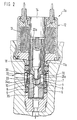
- valve arrangement 2a according to FIG. 2 differs of valve arrangement 2 of FIG. 1 essentially by that a radial distance 22a between the outer armature 17a and the inner anchor 18 is chosen to be smaller than that in FIG Valve arrangement 2 according to Figure 1.
- a tubular transition 24a located chamber 25a supply with pressure medium leaves at least one channel 33, which essentially in radial direction the wall of the tubular transition 24a runs through.
- only one channel 33 is provided whose diameter is essentially a diameter of Control passage 9 corresponds, but also in diameter can be larger or smaller. From the above The difference is that the chamber 25a with the inlet 30 primarily through channel 33 and subordinated through one Annular gap communicated according to the radial distance 22 a.
- the area ratio between the cross section of the Main valve seat 5 and the cross section of the auxiliary valve seat 8 can be selected by the designer. According to the largest too expected pressure drop between inlet 30 and Outlet 29 is the cross section of armature 17 of the first Embodiment or the armature 17a of the second Execution example to choose so that the anchor in question the auxiliary closure piece 10 from its auxiliary valve seat 8 can take off. Then one can for the anchor 17 or 17a radial distance between the armature 18 and the housing 3 be used. On the other hand, if you start from one Cross-section selection as shown in FIG. 2, this results in that by means of the electromagnet 12 and the armature 18 generated force the maximum allowable Cross section and thus diameter of the auxiliary valve seat 8.
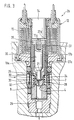
- the first embodiment of the invention Valve arrangement 2b according to FIG. 3 also has a Main valve 4 and an auxiliary valve 7.
- An auxiliary valve 7 associated armature 18a has a first one at pole core 14 Length section 35 with a diameter that is almost as large is like the diameter of the pole core 14.
- the diameter of this length section 36 is chosen to be smaller than the diameter of the armature 17a of the embodiment according to FIG. 2. Closes on the second length section 36 also a plunger 21 on the auxiliary closure piece 10 ends.
- Anchor 17b Similar to the examples in FIGS. 1 and 2 is essentially tubular around the armature 18a Anchor 17b arranged.
- This anchor 17b is opposite Anchors 17 and 17a of the exemplary embodiments according to the figures 1 and 2 shorter, because it ends below first length section 35 of armature 18a.
- the basic position of the valve arrangement 2b is the main valve 4 and the auxiliary valve 7 closed, and between the first Length section 35 of the armature 18a and an upper end face 37 of the armature 17b remains a small distance for one Air gap.
- the anchor 17b also merges into one tubular transition 24.
- the tubular transition 24 is like in the example according to FIG. 2 of at least one channel 33 pulled through.
- the armature 17b can also have at least one longitudinal groove 27a.
- the first length section 35 of the Anchor 18a may be provided with at least one longitudinal groove 27b.
- the longitudinal groove 27b reduces the resistance to movement of the Armature 18a, which is surrounded by pressure medium, and reduced thereby the opening time of the auxiliary valve 7.
- the one shown in FIG. 3 is Position the basic position in which the coil 13 is de-energized. If the coil 13 is used to open the valve arrangement 2b electric current is applied, among other things Polkern 14 flooded and also primarily the first Length section 35 of the armature 18 flooded. Consequently has the anchor 18a compared to the embodiments of FIG Figures 1 and 2 a greater lifting force for lifting the Auxiliary closure piece 10 from its auxiliary valve seat 8. Accordingly, the valve assembly 2b is well suited for large Pressure drop between its inlet 30 and its outlet 29. After opening the auxiliary valve seat 8 is as a result hydraulically generated forces and also as a result electromagnetic forces, the armature 17b moves so that the main valve 4 opens.
- the valve assembly 2b can be securely closed is, is a spring lla, which is supported on the pole core 14 and acts against the armature 18a, somewhat stronger than in the embodiments of Figures 1 and 2.
- the arrangement the opening spring 38 is useful when operating the Valve arrangement 2b with very viscous pressure medium such as Brake fluid takes place, as is the case with, for example Temperatures below -20 ° C are expected.
- the opening spring 38 also in the exemplary embodiments of FIGS. 1 and 2 can be transferred. Accordingly, they would be there Exchange springs 11 for the stronger springs Ila.
- the valve arrangement 2c is the armature 18b the auxiliary closure piece 10 is a stepped, cylindrical Component. It has a first length section 35 which facing the pole core 14 and its diameter almost like this is the same as the diameter of the pole core 14. On this first length section 35 is integral second length section 36 of smaller diameter, which in an anchor 17c for a main closure piece 6a and is led. The first length section 35 has at least one longitudinal groove 27b on its circumference.
- the anchor 18b of the auxiliary closure piece 10 consists of soft magnetic Material. It has an axial bore in which the spring 11 is received, which the armature 18b from the pole core 14th prints. The axial bore settles with a smaller one Diameter through the armature 18b.
- the plunger 21a is at least in the region of the Auxiliary closure piece 10 hardened. It can be shared with others Connected to the armature 18b by being pressed in, for example by welding or by stamping the Anchor 18b at at least one point on its circumference in radial direction.
- the two-piece design of the armature 18b with the plunger 21a and the auxiliary closure piece 10 is easier to manufacture than a one-piece anchor and therefore cheaper.
- the anchor 17c of the main closure piece 6a is a tube formed, which in the direction of the main closure piece 6a tapered in diameter like a sleeve.
- the Main closure piece 6a is a cylindrical component a continuous axial bore.
- At its the Auxiliary closure piece 10 facing end face is a conical auxiliary valve seat 8 formed.
- the other, the Main valve seat 5 facing end of the Main closure piece 6a is spherical.
- the Main closure piece 6a is pressed into the armature 17c, can but also in other known manner with the anchor 17c be connected. It is at least in the area of Auxiliary valve seat 8 and its spherical, with the Main valve seat 5 cooperating end hardened.
- the anchor 17c is made of soft magnetic material. This two-part anchor / locking piece combination can be also easier and therefore cheaper to manufacture than a one-piece anchor.
- the second valve arrangement 2c coincides with the the first embodiment shown in FIG. 3, with the opening spring 38 omitted.
- a ball can be used, which, for example, in a manner known per se on the respective valve seat 5, 8 facing end face in the Anchor 18, 17 is pressed (not shown).
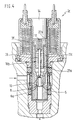
- inventive Valve arrangement 2d has a short housing Pipe section 3a on, like the housing 3 of the previous Embodiments of the invention thin-walled and with the Polkern 14 is hydraulically tightly connected.
- the pipe section 3a continues in a thick-walled tube 3b with which it for example by means of a circumferential weld is hydraulically tightly connected.
- the inside diameter of the Housing 3a, 3b thereby tapers on a pole core 14 facing end of the thick-walled tube 3b.
- An anchor 18c for the auxiliary closure piece 10 is stepped educated. It has a first length section 35 which faces the pole core 14 and at least one longitudinal groove 27b has on its circumference.
- the armature 18c projects with a short intermediate section 39 the pipe 3b and is guided there.
- Another Length section 36a merges in one piece into a plunger 21, the free end of the hemispherical auxiliary closure piece 10 forms.
- the further length section 36a is in one tubular anchor 17d of the main closure piece 6 is added and led.
- the tubular anchor 17d is similar to that in the third Embodiment used anchor 17b formed, has However, a smaller outer diameter that the tapered inner diameter of the tube 3b of the housing is adjusted.
- the front end facing the main valve seat 5 the armature 17d is hemispherical as the main closure piece 6 educated.
- Anchor face 37 of anchor 17d of main closure piece 6 reduced compared to the third valve arrangement 2b Magnetic force on the armature 18c of the auxiliary closure piece 10 is larger, so that the operating force for the Auxiliary valve 7 enlarged and the opening times shortened.
- the magnetic circuit of the valve assembly 2d is with regard to the actuation of the auxiliary valve 7 optimized.
- This hydraulic Vehicle brake system 40 has between one Master brake cylinder 41 and four wheel brakes 42, 43, 44, 45 one Anti-lock device 46 of the so-called return type.
- the wheel brakes 42, 43, 44, 45 are Brake pressure modulation valves 47, 48, 49, 50 and 51, 52, 53, 54 assigned.
- the brake pressure modulation valves 47 up to 50 designed as normally open 2/2-way valves and direct pressure medium, which from the master cylinder 41st is pressed to the wheel brakes 42, 43, 44, 45.
- Die Brake pressure modulation valves 51, 52, 53, 54 are in their normal positions closed and as 2/2-way valves educated.
- valves serve as brake pressure reduction valves and are operated as needed after closing one assigned brake pressure modulation valve 47 or 48 or 49 or 50.
- the brake pressure modulation valves 51 to 54 thus serve, from a respective wheel brake 42, 43, 44, 45 to release pressure medium and a respective one Return pump 55 or 56 to be fed. Any return pump 55, 56 supports the pressure medium supplied to it Pressure increase upstream of the brake pressure modulation valves 47, 48 or 49, 50 and in the event of Blocker protection operation also back to the master brake cylinder 41.
- the anti-lock device is for automatic braking further developed by installing changeover valves 57 and 58 between the master cylinder 41 and the Brake pressure modulation valves 47, 48, 49, 50 and the Outlets 59 and 60 of the return pumps 55 and 56. Des others are between inlets 61 and 62 respectively Return pumps 55 and 56 and the master brake cylinder 41 each a valve assembly 2, 2a or 2b of the type described built-in.
- the switch valves 57 and 58 are included Safety valves 63 and 64 combined. As a result of Arrangement of the changeover valves 57, 58, the safety valves 63, 64 so automatic braking is possible without a Driver a brake pedal assigned to the master brake cylinder 41 65 has to operate.
- this can automatic brakes can be made for example Side slip control of vehicle wheels for the purpose that enlarged by automatic braking lateral wheel slip is to the undesirable large wheel slip of the front of him or behind him moving vehicle wheel at least approximated to reduce the tendency to spin or to End of a spin cycle.
- advanced anti-lock device 46 of course, as already mentioned in the introduction to the description suitable, undesirably high drive slip in driven Automatic braking to lower slip values to regulate.
- valve arrangements 2b, 2c and 2d also in other than the vehicle brake system 40 shown in FIG Advantage are applicable. Because anti-lock devices, Anti-skid control devices and configurations for the Side slip control already belongs to the state of the art, does not need all the details during operation to be received. It is therefore only described that when the brake pedal 65 is not operated, the each used the valve arrangements 2, 2a, 2b, 2c or 2d can be opened quickly because between the master brake cylinder 41 and the respective inlet 61 and 62 of the return pumps 55 and 56 practically no obstacle to opening There is a pressure drop.
- Electromagnets 12 both armatures 17, 18 and 17a, 17b and 18a move at the same time, which makes the Main valve seat 5 is opened and the return pumps 55 and 56, which are designed as self-priming pumps, fill well and accordingly pressure increases quickly can produce their outlets 59 and 60, respectively.
- valve arrangements 2b, 2c and 2d according to the invention also in hydraulic systems other than the one briefly described here Vehicle brake system 40 can be used.
Landscapes
- Engineering & Computer Science (AREA)
- Physics & Mathematics (AREA)
- Mechanical Engineering (AREA)
- Fluid Mechanics (AREA)
- Transportation (AREA)
- General Engineering & Computer Science (AREA)
- Electromagnetism (AREA)
- Magnetically Actuated Valves (AREA)
Description
Claims (15)
- Ventilanordnung (2b, 2c, 2d) bestehend aus einem Gehäuse, einem Hauptventil (4), mit einem Hauptventilsitz (5) und mit einem Hauptventilverschlußstück (6, 6a) und aus einem Hilfsventil (7) mit einem Hilfsventilsitz (8) am Hauptverschlußstück (6, 6a) und einem dieses durchziehenden, vom Hilfsventilsitz (5) ausgehenden Steuerdurchlaß (9), mit einem Hilfsverschlußstück (10), mit einer das Hilfsverschlußstück (10) belasteten Feder (11), mit einem beweglichen Anker (18a, 18b, 18c) zum Wegbewegen des Hilfsverschlußstückes (10) vom Hilfsventilsitz (8), mit einem Elektromagnet (12) für den Anker (18a, 18b, 18c) und mit einem weiteren beweglichen Element (17b, 17c, 17d), das relativ zum Anker (18a, 18b, 18c) des Hilfsverschlußstückes (10) beweglich und magnetisch wirksam ist, wobei das bewegliche, magnetisch wirksame Element als ein zweiter Anker (17b, 17c, 17d) ausgebildet ist, der den Anker (18a, 18b, 18c) des Hilfsverschlußstückes (10) wenigstens auf einem Teil von dessen Länge umgibt und starr mit dem Hauptverschlußstück (6) verbunden ist, und wobei beiden Ankern (17b, 17c, 17d, 18a, 18b, 18c) gemeinsam ein unbeweglich im Elektromagnet (12) angeordneter Polkern (14) zugeordnet ist, dadurch gekennzeichnet, daß der Anker (18a) des Hilfsverschlußstückes (10) beim Polkern (14) einen Längenabschnitt (35) mit einem Durchmesser von im wesentlichen dem Durchmesser des Polkerns (14) und an den ersten Längenabschnitt (35) anschließend einen zweiten Längenabschnitt (36) mit einem kleineren Durchmesser aufweist, und daß bei geschlossenem Hilfsventil (7) der im wesentlichen rohrartig ausgebildete Anker (17b) des Hauptverschlußstückes (6) mit einer Stirnseite (37) einen axialen Mindestabstand vom ersten Längenabschnitt (35) des Ankers (18a) des Hilfsverschlußstückes (10) hat.
- Ventilanordnung anch Anspruch 1, dadurch gekennzeichnet, daß in den äußeren Umfang des ersten Längenabschnitts (35) des Ankers (18a) des Hilfsverschlußstücks (10) eine Längsnut (27b) eingearbeitet ist.
- Ventilanordnung nach Anspruch 1 oder 2, dadurch gekennzeichnet, daß das Hauptverschlußstück (6) und sein Anker (17, 17a, 17b) über einen rohrartigen Übergang (24) miteinander verbunden sind, daß der Übergang (24) hydraulisch dicht ausgebildet ist, und daß ein zwischen den beiden Ankern (17, 17a, 17b, 18, 18a) befindlicher Spalt einen in den rohrartigen Übergang (24) führenden Strömungskanal bildet.
- Ventilanordnung nach Anspruch 1 oder 2, dadurch gekennzeichnet, daß das Hauptverschlußstück (6) und sein Anker (17a, 17b) über einen rohrartigen Übergang (24) miteinander verbunden sind, und daß der rohrartige Übergang (24) von wenigstens einem Kanal (33) durchzogen ist.
- Ventilanordnung nach Anspruch 4, dadurch gekennzeichnet, daß der eine Kanal (33) einen Durchmesser von wenigstens dem Durchmesser des sich an den Hilfsventilsitz (8) anschließenden Steuerkanals (9) hat.
- Ventilanordnung nach einem der Ansprüche 1 bis 4, dadurch gekennzeichnet, daß eine zweite Feder (38) eingebaut ist die als eine Öffnungsfeder für das Hauptversschlußstück (6) und schwächer als die erste Feder (11), die eine Schließfeder ist, ausgebildet ist.
- Ventilanordnung nach Anspruch 1, dadurch gekennzeichnet, daß am äußeren Umfang des ersten Längenabschnitts (35) des Ankers (18a) des Hilfsverschlußstückes (10) wenigstens eine Längsnut (27a) eingearbeitet ist.
- Ventilanordnung nach einem der vorhergehenden Ansprüche, dadurch gekennzeichnet, daß der Anker (18b) des Hilfsverschlußstücks (10) ein zylindrisches Bauteil mit einer axialen Bohrung ist, in der ein Zylinderstift als Stößel (21a) aufgenommen ist, der in Richtung des Hilfsventilsitzes (8) aus dem Anker (18b) vorsteht und dessen dem Hilfsventilsitz (8) zugewandtes Ende als Hilfsverschlußstück (10) ausgebildet ist.
- Ventilanordnung nach Anspruch 8, dadurch gekennzeichnet, daß der Anker (18b) des Hilfsverschlußstücks (10) gestuft ausgebildet ist und auf einem verjüngten Längenabschnitt (36) in dem im wesentlichen rohrartig ausgebildeten Anker (17c) des Hauptverschlußstücks (6a) aufgenommen ist.
- Ventilanordnung nach einem der vorhergehenden Ansprüche, dadurch gekennzeichnet, daß das Hilfsverschlußstück und/oder das Hauptverschlußstück eine Kugel ist.
- Ventilanordnung nach einem der vorhergehenden Ansprüche, dadurch gekennzeichnet, daß der Anker (17c) des Hauptverschlußstücks (6a) ein Rohr ist, in dessen dem Hauptventilsitz (5) zugewandten Ende das Hauptverschlußstück (6a) fest aufgenommen ist.
- Ventilanordnung nach Anspruch 11, dadurch gekennzeichnet, daß das Hauptverschlußstück (6a) ein axial durchbohrtes, zylindrisches Teil ist, dessen dem Hilfsverschlußstück (10) zugewandte Stirnseite als Hilfsventil (8) ausgebildet ist.
- Ventilanordnung nach einem der Ansprüche 8 bis 12, dadurch gekennzeichnet, daß der Anker (17c, 18b) aus einem weichmagnetischen Werkstoff, und daß das Verschlußstück (6a, 10) aus einem harten Material besteht oder zumindest partiell gehärtet ist.
- Ventilanordnung nach einem der vorhergehenden Ansprüche, dadurch gekennzeichnet, daß der Durchmesser des Ankers (17d) des Hauptverschlußstückes (6) kleiner als der Durchmesser des Polkerns (14) ist.
- Hydraulische Fahrzeugbremsanlage (40) mit einem Hauptbremszylinder (41), mit Radbremsen (42, 43, 44, 45) mit Bremsdruckmodulationsventilen (47, 48, 49, 50, 51, 52, 53, 54) und mit wenigstens einer sich durch die Ventilanordnung (2, 2a, 2b) versorgenden selbst ansaugenden Rückförderpumpe (55, 56), in Kombination mit einer Ventilanordnung nach einem der Ansprüche 1 bis 14.
Applications Claiming Priority (5)
| Application Number | Priority Date | Filing Date | Title |
|---|---|---|---|
| DE4441791 | 1994-11-24 | ||
| DE4441791 | 1994-11-24 | ||
| DE19533400A DE19533400A1 (de) | 1994-11-24 | 1995-09-09 | Elektromagnetisch steuerbare Ventilanordnung |
| DE19533400 | 1995-09-09 | ||
| PCT/DE1995/001561 WO1996015926A1 (de) | 1994-11-24 | 1995-11-11 | Elektromagnetisch steuerbare ventilanordnung |
Publications (2)
| Publication Number | Publication Date |
|---|---|
| EP0746485A1 EP0746485A1 (de) | 1996-12-11 |
| EP0746485B1 true EP0746485B1 (de) | 2000-03-01 |
Family
ID=25942248
Family Applications (1)
| Application Number | Title | Priority Date | Filing Date |
|---|---|---|---|
| EP95936432A Expired - Lifetime EP0746485B1 (de) | 1994-11-24 | 1995-11-11 | Elektromagnetisch steuerbare ventilanordnung |
Country Status (4)
| Country | Link |
|---|---|
| US (1) | US5735582A (de) |
| EP (1) | EP0746485B1 (de) |
| JP (1) | JPH09508338A (de) |
| WO (1) | WO1996015926A1 (de) |
Families Citing this family (61)
| Publication number | Priority date | Publication date | Assignee | Title |
|---|---|---|---|---|
| DE19529363A1 (de) * | 1995-08-10 | 1997-02-13 | Bosch Gmbh Robert | Steuerbares Ventil |
| DE19604317A1 (de) * | 1996-02-07 | 1997-08-14 | Bosch Gmbh Robert | Elektromagnetisch betätigtes Ventil, insbesondere für hydraulische Bremsanlagen von Kraftfahrzeugen |
| DE19626304A1 (de) * | 1996-07-01 | 1998-01-08 | Teves Gmbh Alfred | Hydraulische Bremsanlage mit einer Vorladeeinrichtung |
| KR100523702B1 (ko) * | 1996-07-01 | 2006-02-28 | 아이티티 매뉴팩츄어링 엔터프라이즈, 인코포레이티드 | 예충전장치가구비된유압제동장치 |
| JP3551221B2 (ja) * | 1996-09-10 | 2004-08-04 | 日清紡績株式会社 | 液圧ブレーキ装置における液圧制御弁装置 |
| JP3598409B2 (ja) * | 1996-09-10 | 2004-12-08 | 日清紡績株式会社 | 液圧ブレーキ装置における液圧制御弁装置 |
| DE19638898A1 (de) * | 1996-09-23 | 1998-03-26 | Teves Gmbh Alfred | Hydraulische Kraftfahrzeugbremsanlage mit Radschlupfregelung |
| DE19645643A1 (de) * | 1996-11-06 | 1998-05-07 | Braun Ag | Überdruckventil für eine Munddusche |
| US6079799A (en) * | 1996-12-24 | 2000-06-27 | Denso Corporation | Brake system |
| JP2000511491A (ja) * | 1997-03-13 | 2000-09-05 | ローベルト ボツシユ ゲゼルシヤフト ミツト ベシユレンクテル ハフツング | ハイドロリック作動式の遮断弁およびハイドロリック式の車両ブレーキ装置 |
| JPH10267157A (ja) * | 1997-03-25 | 1998-10-09 | Unisia Jecs Corp | 電磁弁およびブレーキ装置 |
| DE19725241B4 (de) * | 1997-06-14 | 2006-06-01 | Continental Teves Ag & Co. Ohg | Verfahren zum Ansteuern einer Kraftfahrzeugbremsanlage |
| JP2009008269A (ja) * | 1997-08-08 | 2009-01-15 | Denso Corp | 差圧制御弁、差圧制御弁の検査方法、差圧制御弁の調整方法、及び車両用ブレーキ装置 |
| DE19855667A1 (de) * | 1997-12-05 | 1999-08-26 | Denso Corp | Magnetventil und Bremssystem mit einem Magnetventil |
| WO1999050116A1 (de) * | 1998-03-31 | 1999-10-07 | Continental Teves Ag & Co. Ohg | Elektromagnetventil |
| US6254200B1 (en) * | 1998-10-30 | 2001-07-03 | Kelsey-Hayes Company | Supply valve for a hydraulic control unit of a vehicular braking system |
| JP4176918B2 (ja) * | 1998-11-09 | 2008-11-05 | 株式会社不二工機 | 電磁弁 |
| EP1163138B1 (de) * | 1999-03-24 | 2003-05-14 | Lucas Industries Public Limited Company | Blockiergeschützte bremsanlage |
| DE19955886A1 (de) * | 1999-11-20 | 2001-05-23 | Bosch Gmbh Robert | Magnetventil mit einem Rückschlagventil |
| DE10010734A1 (de) * | 2000-03-04 | 2001-09-06 | Continental Teves Ag & Co Ohg | Elektromagnetventil, insbesondere für schlupfgeregelte Kraftfahrzeugbremsanlagen |
| DE10036577A1 (de) * | 2000-07-27 | 2002-02-07 | Bosch Gmbh Robert | Elektromagnetisch betätigtes Ventil, insbesondere für hydraulische Bremsanlagen von Kraftfahrzeugen |
| JP3651372B2 (ja) * | 2000-08-04 | 2005-05-25 | トヨタ自動車株式会社 | 車輌用制動制御装置 |
| KR100611337B1 (ko) * | 2001-09-19 | 2006-08-11 | 주식회사 만도 | 브레이크시스템용 솔레노이드밸브 |
| KR100589665B1 (ko) * | 2001-10-15 | 2006-06-14 | 주식회사 만도 | 브레이크시스템용 솔레노이드밸브 |
| JP3819867B2 (ja) * | 2002-05-15 | 2006-09-13 | 日信工業株式会社 | 電磁弁 |
| KR100491917B1 (ko) * | 2002-05-30 | 2005-05-27 | 현대모비스 주식회사 | 안티로크 브레이크 장치용 솔레노이드 밸브 |
| USD533622S1 (en) | 2003-10-01 | 2006-12-12 | Water Pik, Inc. | End-of-faucet filter |
| US7326334B2 (en) * | 2003-10-01 | 2008-02-05 | Instapure Brands, Inc. | End-of-faucet filter |
| DE102004018191A1 (de) * | 2003-11-26 | 2005-07-14 | Robert Bosch Gmbh | Verfahren zum Ansteuern eines zweistufigen Schaltventils |
| EP1694544B1 (de) * | 2003-11-26 | 2007-07-18 | Robert Bosch Gmbh | Verfahren zum ansteuern eines zweistufigen schaltventils |
| US7198249B2 (en) * | 2005-06-22 | 2007-04-03 | Continental Teves, Inc. | Electromagnetic shuttle valve |
| GB2430246B (en) * | 2005-09-01 | 2008-11-12 | Artemis Intelligent Power Ltd | Valve for a fluid-working machine |
| RU2420683C2 (ru) * | 2006-09-08 | 2011-06-10 | Артемис Интеллиджент Пауэр Лимитед | Устройство для приведения в движение текучей среды и клапанный механизм |
| JP4994455B2 (ja) | 2006-09-08 | 2012-08-08 | アルテミス インテリジェント パワー リミティド | 流体作動機械およびその弁構成 |
| US8322376B2 (en) * | 2008-06-09 | 2012-12-04 | Bendix Commercial Vehicle Systems, Llc | Solenoid valve |
| GB0811385D0 (en) * | 2008-06-20 | 2008-07-30 | Artemis Intelligent Power Ltd | Fluid working machines and method |
| RU2482370C2 (ru) * | 2008-09-09 | 2013-05-20 | Артемис Интеллиджент Пауэр Лимитед | Клапанный узел |
| DE102008064408A1 (de) * | 2008-12-22 | 2010-06-24 | Robert Bosch Gmbh | Vorgesteuertes Ventil und ventilgesteuerte Hydromaschine |
| JP5421059B2 (ja) * | 2009-10-21 | 2014-02-19 | 豊興工業株式会社 | 電磁弁 |
| DE102011076556A1 (de) * | 2011-05-26 | 2012-11-29 | Continental Teves Ag & Co. Ohg | Elektromagnetventil, insbesondere für schlupfgeregelte Kraftfahrzeugbremsanlagen |
| DE102012206604A1 (de) * | 2012-04-20 | 2013-10-24 | Hyptec Gmbh | Elektromagnetisches Ventil für ein Behälterventil einer Kraftstoffversorgungsanlage |
| CN104870874A (zh) * | 2013-02-11 | 2015-08-26 | 丹佛斯公司 | 具有安排在活塞内的电枢的磁阀 |
| DE102013223103A1 (de) * | 2013-09-23 | 2015-04-09 | Robert Bosch Gmbh | Ventil, insbesondere Magnetventil |
| DE102014106940B4 (de) | 2014-05-16 | 2023-08-24 | Mesa Parts GmbH | Elektromagnetisch betätigbares Hochdruckgasventil |
| EP2952794A1 (de) | 2014-06-04 | 2015-12-09 | Danfoss A/S | Magnetventil |
| LU92718B1 (en) * | 2015-05-13 | 2016-11-14 | Luxembourg Patent Co | Electromagnetic valve with magnetically actuated main and pilot valve elements |
| DE102015109077A1 (de) * | 2015-06-09 | 2016-12-15 | Kendrion (Villingen) Gmbh | Volumenstromgeregeltes Sitzventil |
| JP6253623B2 (ja) * | 2015-09-14 | 2017-12-27 | 本田技研工業株式会社 | 燃料遮断弁 |
| DE102016219994A1 (de) * | 2016-10-13 | 2018-05-09 | Robert Bosch Gmbh | Magnetventil und hydraulisches Bremssystem für ein Fahrzeug |
| WO2018109036A1 (en) | 2016-12-14 | 2018-06-21 | Danfoss A/S | Valve arrangement, pipe arrangement and air conditioning system |
| US10753498B2 (en) * | 2018-01-25 | 2020-08-25 | Mac Valves, Inc. | Flow-through liquid valve |
| DE102018215380A1 (de) * | 2018-09-11 | 2020-03-12 | Robert Bosch Gmbh | Ventilvorrichtung für ein gasförmiges Medium und Tankvorrichtung zur Speicherung eines gasförmigen Mediums |
| JP7266415B2 (ja) * | 2019-01-31 | 2023-04-28 | 川崎重工業株式会社 | ガス用電磁弁 |
| JP7175208B2 (ja) * | 2019-01-31 | 2022-11-18 | 川崎重工業株式会社 | ガス用電磁弁 |
| AT16929U1 (de) * | 2019-05-28 | 2020-12-15 | Zieger Dipl Ing Andreas | Kombinationsventil |
| AT17317U1 (de) * | 2019-09-03 | 2021-12-15 | Andreas Zieger Dipl Ing | Druckregelventil |
| DE102019216715A1 (de) * | 2019-10-30 | 2021-05-06 | Robert Bosch Gmbh | Zweistufiges Magnetventil |
| JP7523249B2 (ja) * | 2020-04-27 | 2024-07-26 | 川崎重工業株式会社 | 弁装置 |
| CN116868014A (zh) * | 2021-03-01 | 2023-10-10 | 丹佛斯有限公司 | 用于制冷和/或空气调节应用的主动平衡阀 |
| DE102022203734A1 (de) * | 2022-04-13 | 2023-10-19 | Robert Bosch Gesellschaft mit beschränkter Haftung | Absperrventil und Tanksystem mit einem Absperrventil |
| KR102642949B1 (ko) * | 2022-07-26 | 2024-02-29 | 주식회사 현대케피코 | 연료탱크용 고압밸브 |
Family Cites Families (10)
| Publication number | Priority date | Publication date | Assignee | Title |
|---|---|---|---|---|
| DE1168725B (de) * | 1960-07-21 | 1964-04-23 | Erich Herion | Durchgangsmagnetventil mit elektromagnetischer Hilfsventilausloesung |
| US3405906A (en) * | 1966-08-04 | 1968-10-15 | Itt | Solenoid pilot operated valve |
| CH591038A5 (de) * | 1975-06-27 | 1977-08-31 | Lucifer Sa | |
| US4174824A (en) * | 1977-05-13 | 1979-11-20 | Eaton Corporation | Pressure operated pilot control shut-off valve |
| GB8913541D0 (en) * | 1989-06-10 | 1989-08-02 | Lucas Ind Plc | Improvements in fluid flow valve assemblies |
| DE3931307A1 (de) * | 1989-09-20 | 1991-03-28 | Bosch Gmbh Robert | Blockierschutzvorrichtung |
| DE3931742A1 (de) * | 1989-09-22 | 1991-04-04 | Knorr Bremse Ag | Magnetventil |
| DE4202389A1 (de) * | 1992-01-29 | 1993-08-05 | Bosch Gmbh Robert | Hydraulische bremsanlage, insbesondere fuer kraftfahrzeuge |
| DE4213740A1 (de) * | 1992-04-25 | 1993-10-28 | Bosch Gmbh Robert | Verfahren zum Beschleunigen des Bremseneingriffs im Antriebsschlupfregelbetrieb und hydraulische Bremsanlage zur Durchführung des Verfahrens |
| DE4232311C1 (de) * | 1992-09-26 | 1994-02-24 | Bosch Gmbh Robert | Hydraulische Fahrzeugbremsanlage mit Blockierschutzeinrichtung |
-
1995
- 1995-11-11 WO PCT/DE1995/001561 patent/WO1996015926A1/de not_active Ceased
- 1995-11-11 US US08/682,598 patent/US5735582A/en not_active Expired - Fee Related
- 1995-11-11 JP JP51643695A patent/JPH09508338A/ja active Pending
- 1995-11-11 EP EP95936432A patent/EP0746485B1/de not_active Expired - Lifetime
Also Published As
| Publication number | Publication date |
|---|---|
| WO1996015926A1 (de) | 1996-05-30 |
| JPH09508338A (ja) | 1997-08-26 |
| EP0746485A1 (de) | 1996-12-11 |
| US5735582A (en) | 1998-04-07 |
Similar Documents
| Publication | Publication Date | Title |
|---|---|---|
| EP0746485B1 (de) | Elektromagnetisch steuerbare ventilanordnung | |
| DE19528726C2 (de) | Elektromagnetisches Ventil | |
| EP0783422B1 (de) | Steuerbares ventil | |
| EP0951412B1 (de) | Magnetventil | |
| EP0625107B1 (de) | Elektromagnetventil, insbesondere für hydraulische bremsanlagen mit schlupfregelung | |
| EP0941187B1 (de) | Mehrwegeventil | |
| DE4028447A1 (de) | Elektromagnetventil fuer hydraulische bremsanlagen mit schlupfregelung | |
| DE19530899A1 (de) | Magnetventil, insbesondere für eine schlupfgeregelte, hydraulische Bremsanlage für Kraftfahrzeuge | |
| DE112009005460B4 (de) | Elektromagnetisches linearventil | |
| DE19533400A1 (de) | Elektromagnetisch steuerbare Ventilanordnung | |
| EP0681128A1 (de) | Magnetventil | |
| DE4312414B4 (de) | Ventilanordnung für eine Bremsblockierschutz-Einrichtung | |
| DE102013218121A1 (de) | Elektromagnetventil, insbesondere für schlupfgeregelte Kraftfahrzeug-Bremsanlagen | |
| DE102016219994A1 (de) | Magnetventil und hydraulisches Bremssystem für ein Fahrzeug | |
| DE19531007A1 (de) | Magnetventil, insbesondere für eine schlupfgeregelte, hydraulische Bremsanlage für Kraftfahrzeuge | |
| DE4339694A1 (de) | Elektromagnetisch betätigtes Ventil, insbesondere für schlupfgeregelte hydraulische Bremsanlagen in Kraftfahrzeugen | |
| DE19531009A1 (de) | Magnetventil, insbesondere für eine schlupfgeregelte, hydraulische Bremsanlage für Kraftfahrzeuge | |
| DE4439695A1 (de) | Magnetventil und dessen Verwendung | |
| DE10030659A1 (de) | Schaltbares Solenoidventil zur Verwendung in einem Bremssystem mit Antiblockier-Betriebsart | |
| EP0182053B1 (de) | Elektromagnetisch betätigbares Druckregelventil | |
| DE69502730T2 (de) | Elektroventil für hydraulische druckregelung und anwendung in bremsanlagen | |
| DE3705514C2 (de) | ||
| EP1907252B1 (de) | Fahrzeugbremsanlagen-magnetventilanordnung | |
| EP0966380B1 (de) | Druckregelventil | |
| DE19518333A1 (de) | Elektromagnetische Ventilanordnung und Fahrzeugbremssystem mit dieser elektromagnetischen Ventilanordnung |
Legal Events
| Date | Code | Title | Description |
|---|---|---|---|
| PUAI | Public reference made under article 153(3) epc to a published international application that has entered the european phase |
Free format text: ORIGINAL CODE: 0009012 |
|
| AK | Designated contracting states |
Kind code of ref document: A1 Designated state(s): DE GB SE |
|
| 17P | Request for examination filed |
Effective date: 19961202 |
|
| 17Q | First examination report despatched |
Effective date: 19980724 |
|
| GRAG | Despatch of communication of intention to grant |
Free format text: ORIGINAL CODE: EPIDOS AGRA |
|
| GRAG | Despatch of communication of intention to grant |
Free format text: ORIGINAL CODE: EPIDOS AGRA |
|
| GRAH | Despatch of communication of intention to grant a patent |
Free format text: ORIGINAL CODE: EPIDOS IGRA |
|
| GRAH | Despatch of communication of intention to grant a patent |
Free format text: ORIGINAL CODE: EPIDOS IGRA |
|
| GRAA | (expected) grant |
Free format text: ORIGINAL CODE: 0009210 |
|
| AK | Designated contracting states |
Kind code of ref document: B1 Designated state(s): DE GB SE |
|
| REF | Corresponds to: |
Ref document number: 59507917 Country of ref document: DE Date of ref document: 20000406 |
|
| GBT | Gb: translation of ep patent filed (gb section 77(6)(a)/1977) |
Effective date: 20000511 |
|
| EN | Fr: translation not filed | ||
| PGFP | Annual fee paid to national office [announced via postgrant information from national office to epo] |
Ref country code: GB Payment date: 20001018 Year of fee payment: 6 |
|
| PGFP | Annual fee paid to national office [announced via postgrant information from national office to epo] |
Ref country code: SE Payment date: 20001121 Year of fee payment: 6 |
|
| PLBE | No opposition filed within time limit |
Free format text: ORIGINAL CODE: 0009261 |
|
| STAA | Information on the status of an ep patent application or granted ep patent |
Free format text: STATUS: NO OPPOSITION FILED WITHIN TIME LIMIT |
|
| 26N | No opposition filed | ||
| PG25 | Lapsed in a contracting state [announced via postgrant information from national office to epo] |
Ref country code: GB Free format text: LAPSE BECAUSE OF NON-PAYMENT OF DUE FEES Effective date: 20011111 |
|
| PG25 | Lapsed in a contracting state [announced via postgrant information from national office to epo] |
Ref country code: SE Free format text: LAPSE BECAUSE OF NON-PAYMENT OF DUE FEES Effective date: 20011112 |
|
| REG | Reference to a national code |
Ref country code: GB Ref legal event code: IF02 |
|
| EUG | Se: european patent has lapsed |
Ref document number: 95936432.4 |
|
| PGFP | Annual fee paid to national office [announced via postgrant information from national office to epo] |
Ref country code: DE Payment date: 20130124 Year of fee payment: 18 |
|
| PG25 | Lapsed in a contracting state [announced via postgrant information from national office to epo] |
Ref country code: DE Free format text: LAPSE BECAUSE OF NON-PAYMENT OF DUE FEES Effective date: 20140603 |
|
| REG | Reference to a national code |
Ref country code: DE Ref legal event code: R119 Ref document number: 59507917 Country of ref document: DE Effective date: 20140603 |