EP1262659A2 - Kraftstoffsystem für eine Brennkraftmaschine - Google Patents
Kraftstoffsystem für eine Brennkraftmaschine Download PDFInfo
- Publication number
- EP1262659A2 EP1262659A2 EP02011016A EP02011016A EP1262659A2 EP 1262659 A2 EP1262659 A2 EP 1262659A2 EP 02011016 A EP02011016 A EP 02011016A EP 02011016 A EP02011016 A EP 02011016A EP 1262659 A2 EP1262659 A2 EP 1262659A2
- Authority
- EP
- European Patent Office
- Prior art keywords
- fuel
- pressure
- internal combustion
- combustion engine
- valve device
- Prior art date
- Legal status (The legal status is an assumption and is not a legal conclusion. Google has not performed a legal analysis and makes no representation as to the accuracy of the status listed.)
- Granted
Links
Images

Classifications
-
- F—MECHANICAL ENGINEERING; LIGHTING; HEATING; WEAPONS; BLASTING
- F02—COMBUSTION ENGINES; HOT-GAS OR COMBUSTION-PRODUCT ENGINE PLANTS
- F02M—SUPPLYING COMBUSTION ENGINES IN GENERAL WITH COMBUSTIBLE MIXTURES OR CONSTITUENTS THEREOF
- F02M63/00—Other fuel-injection apparatus having pertinent characteristics not provided for in groups F02M39/00 - F02M57/00 or F02M67/00; Details, component parts, or accessories of fuel-injection apparatus, not provided for in, or of interest apart from, the apparatus of groups F02M39/00 - F02M61/00 or F02M67/00; Combination of fuel pump with other devices, e.g. lubricating oil pump
- F02M63/02—Fuel-injection apparatus having several injectors fed by a common pumping element, or having several pumping elements feeding a common injector; Fuel-injection apparatus having provisions for cutting-out pumps, pumping elements, or injectors; Fuel-injection apparatus having provisions for variably interconnecting pumping elements and injectors alternatively
- F02M63/0225—Fuel-injection apparatus having a common rail feeding several injectors ; Means for varying pressure in common rails; Pumps feeding common rails
-
- F—MECHANICAL ENGINEERING; LIGHTING; HEATING; WEAPONS; BLASTING
- F02—COMBUSTION ENGINES; HOT-GAS OR COMBUSTION-PRODUCT ENGINE PLANTS
- F02M—SUPPLYING COMBUSTION ENGINES IN GENERAL WITH COMBUSTIBLE MIXTURES OR CONSTITUENTS THEREOF
- F02M63/00—Other fuel-injection apparatus having pertinent characteristics not provided for in groups F02M39/00 - F02M57/00 or F02M67/00; Details, component parts, or accessories of fuel-injection apparatus, not provided for in, or of interest apart from, the apparatus of groups F02M39/00 - F02M61/00 or F02M67/00; Combination of fuel pump with other devices, e.g. lubricating oil pump
- F02M63/0012—Valves
- F02M63/0031—Valves characterized by the type of valves, e.g. special valve member details, valve seat details, valve housing details
- F02M63/005—Pressure relief valves
- F02M63/0052—Pressure relief valves with means for adjusting the opening pressure, e.g. electrically controlled
-
- F—MECHANICAL ENGINEERING; LIGHTING; HEATING; WEAPONS; BLASTING
- F02—COMBUSTION ENGINES; HOT-GAS OR COMBUSTION-PRODUCT ENGINE PLANTS
- F02M—SUPPLYING COMBUSTION ENGINES IN GENERAL WITH COMBUSTIBLE MIXTURES OR CONSTITUENTS THEREOF
- F02M63/00—Other fuel-injection apparatus having pertinent characteristics not provided for in groups F02M39/00 - F02M57/00 or F02M67/00; Details, component parts, or accessories of fuel-injection apparatus, not provided for in, or of interest apart from, the apparatus of groups F02M39/00 - F02M61/00 or F02M67/00; Combination of fuel pump with other devices, e.g. lubricating oil pump
- F02M63/02—Fuel-injection apparatus having several injectors fed by a common pumping element, or having several pumping elements feeding a common injector; Fuel-injection apparatus having provisions for cutting-out pumps, pumping elements, or injectors; Fuel-injection apparatus having provisions for variably interconnecting pumping elements and injectors alternatively
- F02M63/0225—Fuel-injection apparatus having a common rail feeding several injectors ; Means for varying pressure in common rails; Pumps feeding common rails
- F02M63/023—Means for varying pressure in common rails
- F02M63/0235—Means for varying pressure in common rails by bleeding fuel pressure
- F02M63/025—Means for varying pressure in common rails by bleeding fuel pressure from the common rail
-
- F—MECHANICAL ENGINEERING; LIGHTING; HEATING; WEAPONS; BLASTING
- F02—COMBUSTION ENGINES; HOT-GAS OR COMBUSTION-PRODUCT ENGINE PLANTS
- F02D—CONTROLLING COMBUSTION ENGINES
- F02D2250/00—Engine control related to specific problems or objectives
- F02D2250/02—Fuel evaporation in fuel rails, e.g. in common rails
-
- F—MECHANICAL ENGINEERING; LIGHTING; HEATING; WEAPONS; BLASTING
- F02—COMBUSTION ENGINES; HOT-GAS OR COMBUSTION-PRODUCT ENGINE PLANTS
- F02M—SUPPLYING COMBUSTION ENGINES IN GENERAL WITH COMBUSTIBLE MIXTURES OR CONSTITUENTS THEREOF
- F02M2200/00—Details of fuel-injection apparatus, not otherwise provided for
- F02M2200/60—Fuel-injection apparatus having means for facilitating the starting of engines, e.g. with valves or fuel passages for keeping residual pressure in common rails
Definitions
- the invention first relates to a fuel system for an internal combustion engine, with a fuel tank, with at least one fuel pump, with a fuel manifold, which is fed by the fuel pump, with a valve device with which the pressure in the Fuel rail can be controlled and with at least one fuel injector through which the fuel into a combustion chamber of the internal combustion engine can reach.
- Such a fuel system is known from DE 195 39 883 A1 known.
- two connected in series Pump the fuel from a fuel tank into one Fuel manifold, which is commonly referred to as a "rail" referred to as.
- the Fuel stored under relatively high pressure.
- To the Fuel manifolds are injectors connected that directly into the fuel Inject combustion chambers.
- the pressure in the fuel rail is indicated by a Pressure valve controlled.
- fuel from the fuel rail via a Return line returned to the fuel tank. at the known fuel system is switched off after the Pressure in the fuel rail reduced. by virtue of from heat conduction from the engine block, however, it can in the one in the fuel rail Fuel to form vapor bubbles which are the Difficult to restart the engine.
- the disadvantage is in the known Fuel system when starting the internal combustion engine Pressure of the first of the two fuel pumps delivered fuel increased to, if necessary existing vapor bubbles as quickly as possible Eliminate fuel system. However, this requires one certain time.
- the present invention has the task of a Fuel system of the type mentioned above train that one with the fuel system operated internal combustion engine as quickly as possible also in hot state can be started.
- This task is the beginning of a fuel system mentioned type in that the valve device so is trained that at least in normal Operating pressure in the fuel rail in the not actuated state is closed.
- the method according to the invention has the advantage that Vapor bubbles cannot form at all because the pressure in the fuel rail at a high level too is held when the internal combustion engine is switched off. Consequently no action is required to take before Possible restarting a hot internal combustion engine Remove vapor bubbles from the fuel system.
- Valve device is designed so that it is not in your actuated hibernation is closed, so none Connection back from the fuel rail for example to the fuel tank exists. On such unactuated state is generally anyway with the internal combustion engine turned off.
- Valve device is operated electrically and in de-energized state at least at normal pressure in the Fuel rail is closed.
- electrical actuated valve devices are very simple and inexpensive to manufacture.
- a de-energized state is in parked internal combustion engine also easy realizable.
- valve device it is also possible for the valve device to have a Preloading device which comprises a valve element in Closing direction applied.
- a biasing device can be, for example, a spring include. The valve element is thus actuated against the force of the pretensioner.
- Such Valve device is simple to build and works reliably.
- the pretensioning device can be selected so that the valve device opens when not actuated, when the pressure in the fuel rail is one exceeds a certain value. This measure will ensures that the pressure in the fuel rail with the internal combustion engine turned off cannot exceed the maximum value. This will make the Functional reliability of the fuel rail and connected components guaranteed because of heating of the trapped in the fuel rail Fuel, for example, due to the heat conduction of the internal combustion engine and the associated Expansion of the enclosed fuel not to one Damage to the Krafttoff manifold or included components.
- the opening pressure the valve device in the non-actuated state lower is the maximum permissible functional pressure Fuel injector.
- This training of fuel system according to the invention bears the fact Bill that the usual fuel injectors from a certain pressure in the Fuel manifold can no longer be operated safely can. There is also a risk that if exceeded the maximum permissible functional pressure the fuel injector no longer closes securely and therefore Fuel with the internal combustion engine stopped Combustion chamber of the internal combustion engine arrives. Through the Further development according to the invention prevents all of this.
- the opening pressure of the Valve device at high engine speed is higher than at low engine speed. Because of this measure, the fact becomes Taken into account that it is for a consumption and Low-emission operation of the internal combustion engine cheap is when the pressure of the fuel at the fuel injector at low speed the Internal combustion engine is rather low and at high speed the internal combustion engine is rather high.
- the opening pressure of the Valve device ensures that each one Operating state of the internal combustion engine corresponding pressure in the fuel rail.
- the invention also relates to an internal combustion engine, especially for motor vehicles, which a Fuel system includes with a fuel tank, with at least one fuel pump, with a fuel manifold, which is fed by the fuel pump, with a valve device with which the pressure in the Fuel rail can be controlled and with at least one fuel injector through which the fuel into a combustion chamber of the internal combustion engine can reach.
- a Fuel system includes with a fuel tank, with at least one fuel pump, with a fuel manifold, which is fed by the fuel pump, with a valve device with which the pressure in the Fuel rail can be controlled and with at least one fuel injector through which the fuel into a combustion chamber of the internal combustion engine can reach.
- Valve device of the fuel system is designed that they are at least at normal pressure in the fuel rail is closed in the unconfirmed state.
- the invention further relates to a method for operating an internal combustion engine, in particular for motor vehicles, where the fuel comes from a fuel tank at least one fuel pump in a fuel rail and from there via a fuel injector into a combustion chamber of the Internal combustion engine is promoted and in which the pressure in the fuel rail via a valve device is controlled.
- Valve device at least at normal pressure in the Fuel manifold when not operated closed is.
- an internal combustion engine carries this overall Reference numeral 10. It is in the present Embodiment only symbolically by a dash-dotted line indicated.
- the internal combustion engine 10 in turn comprises a fuel system 12.
- the high pressure fuel pump 22 compresses that of the electric fuel pump 16 pre-compressed fuel and feeds it into a fuel rail 26.
- This is commonly referred to as "rail".
- rail In it is the fuel during the operation of the internal combustion engine 10 under very high pressure, up to about 120 bar, saved.
- To the fuel rail 26 are multiple fuel injectors 28 connected. These are injectors, which the fuel directly into corresponding combustion chambers 30 inject.
- Fuel can be petrol act just like diesel.
- the pressure in the fuel rail 26 is one Pressure sensor 32 detected. This delivers signals to Control and regulating device 34.
- the fuel rail 26 is via a fuel connection 36 with the Fuel connection 18 connected.
- a pressure valve 38 is arranged, the exact design of which is explained below.
- the pressure valve 38 is controlled by the control and regulating device 34 driven.
- the pressure valve 38 is constructed in detail as follows (see Fig. 2):
- Fig. 2 shows a cylindrical valve body 40 which in Installation position in a cylindrical recess of one in FIG. 2 not shown receiving part used and on this is attached. On this recording part are also Connections for the fuel connection 36 are present.
- the between the pressure valve 38 and the high pressure fuel pump 22 lying area of The fuel connection bears the reference symbol 36a, whereas the one pointing to the fuel connection 18 Area bears the reference symbol 36b.
- the valve body 40 is constructed in two parts.
- lower part 42 is a coaxial to valve body 40 Through hole 44 is present, which is shown in Fig. 2 flared at the top.
- the conical extension (without Reference number) forms a valve seat for a valve ball 46.
- the upper part 48 of the valve body 40 in FIG. 2 one also coaxial to the valve body 40 Through hole 50 is present, two of which are radial Branch the running bores 52.
- the through hole 44 in the lower part 42 of the valve body 40 is with the Inlet of the pressure valve 38 and thus in the installed position with the Line 36a connected, whereas the radial bores 52nd to an outlet of the pressure valve 38 and thus in Lead installation position to line 36b.
- Valve tappet 54 In the central through bore 50 is a Valve tappet 54 arranged on the upper in Fig. 2 End portion of a magnetic armature 56 is attached.
- the Valve tappet 54 is in the area of the through bore 50 in a sliding bushing (not shown).
- a sleeve 58 on the outer lateral surface of the upper part 48 attached, in turn with its upper area in Fig. 3 is connected to a housing body 60.
- a in Fig. 2 open down blind hole 62 is present.
- a guide ring 64 is used at the bottom in Fig. 2 .
- the top one End 66 of the valve lifter 54 slidably.
- the top End 66 of valve lifter 54 is supported by a compression spring 68 acted on at the base of the blind hole 62 in Housing body 60 supports.
- About the compression spring 68 and the Valve tappet 54 is ultimately the valve ball 46 against the Valve seat in the through bore 44 in the lower part 42 of the valve body 40 pressed.
- a retaining ring 70 is attached to the outside of the housing body 60.
- the retaining ring 70 protrudes radially from the housing body 60 and is coaxial with it overall.
- On the radially outer one The edge region of the retaining ring 70 is two bracket elements 72 attached, which encompass a magnetic winding 74.
- the upper Area of the housing body 60, the retaining ring 70 and the Strap elements 72 are extrusion-coated with plastic 76.
- the Valve ball 46 If no current flows through the magnetic winding 74, the Valve ball 46 with the full force of the compression spring 68 against pressed the valve seat. So in this case it is Pressure valve 38 closed.
- the compression spring 68 is however dimensioned such that the valve ball 46 against the Force of the compression spring 68 lifts off the valve seat when the Pressure in the fuel rail 26 a maximum permissible value exceeds. That way ensures that if the magnet winding 74 is not can be energized more because, for example, the Power supply is interrupted by a defect that Pressure in the fuel rail 26 a maximum permissible value does not exceed.
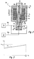
- a variable energization of the magnet winding 74 makes it possible to adapt the opening pressure of the pressure valve 38 to the speed of the internal combustion engine 10. For reasons of emissions and fuel consumption, it is desirable that the fuel pressure applied to the fuel injection devices 28 be lower at low engine speeds 10 than at high speeds. This is normally achieved by energizing the magnetic winding 74 accordingly. If the power supply to the magnet winding 74 is interrupted, for example due to a dropped connector, the opening of the pressure valve 38 can be realized by designing the geometry of the valve seat 46 accordingly, as shown in FIG. 3. The opening pressure PO of the pressure valve 38 increases with the speed n. In any case, it is ensured that the opening pressure PO of the pressure valve 38 is lower than the maximum permissible functional pressure PV max of the fuel injection devices 28.
Landscapes
- Engineering & Computer Science (AREA)
- Chemical & Material Sciences (AREA)
- Combustion & Propulsion (AREA)
- Mechanical Engineering (AREA)
- General Engineering & Computer Science (AREA)
- Fuel-Injection Apparatus (AREA)
- Electrical Control Of Air Or Fuel Supplied To Internal-Combustion Engine (AREA)
Abstract
Description
- Fig. 1:
- ein Blockschaltbild einer Brennkraftmaschine mit einem Kraftstoffsystem mit einer Ventileinrichtung;
- Fig. 2:
- einen teilweisen Schnitt durch die Ventileinrichtung von Fig. 1; und
- Fig. 3:
- ein Diagramm, in dem der Öffnungsdruck der Ventileinrichtung von Fig. 2 über der Drehzahl der Brennkraftmaschine aufgetragen ist.
Claims (8)
- Kraftstoffsystem (12) für eine Brennkraftmaschine (10), mit einem Kraftstoffbehälter (14), mit mindestens einer Kraftstoffpumpe (16, 22), mit einer Kraftstoff-Sammelleitung (26), die von der Kraftstoffpumpe (22) gespeist wird, mit einer Ventileinrichtung (38), mit der der Druck in der Kraftstoff-Sammelleitung (26) gesteuert werden kann, und mit mindestens einer Kraftstoff-Einspritzvorrichtung (28), über die der Kraftstoff in einen Brennraum (30) der Brennkraftmaschine (10) gelangen kann, dadurch gekennzeichnet, dass die Ventileinrichtung (38) so ausgebildet ist, dass sie mindestens beim normalen Betriebsdruck in der Kraftstoff-Sammelleitung (26) im nicht betätigten Zustand geschlossen ist.
- Kraftstoffsystem (12) nach Anspruch 1, dadurch gekennzeichnet, dass die Ventileinrichtung (38) elektrisch betätigt wird und im stromlosen Zustand mindestens bei normalem Druck in der Kraftstoff-Sammelleitung (26) geschlossen ist.
- Kraftstoffsystem (12) nach einem der Ansprüche 1 oder 2, dadurch gekennzeichnet, dass die Ventileinrichtung (38) eine Vorspanneinrichtung (68) umfasst, welche ein Ventilelement (46) in Schließrichtung beaufschlagt.
- Kraftstoffsystem (12) nach Anspruch 3, dadurch gekennzeichnet, dass die Vorspanneinrichtung (68) so ausgebildet ist, dass die Ventileinrichtung (38) im nicht betätigten Zustand öffnet, wenn der Druck in der Kraftstoff-Sammelleitung (26) einen bestimmten Wert überschreitet.
- Kraftstoffsystem (12) nach Anspruch 4, dadurch gekennzeichnet, dass der Öffnungsdruck der Ventileinrichtung (38) im nicht betätigten Zustand niedriger ist als der maximal zulässige Funktionsdruck der Kraftstoff-Einspritzvorrichtung (28).
- Kraftstoffsystem (12) nach einem der Ansprüche 3 bis 5, dadurch gekennzeichnet, dass der Öffnungsdruck der Ventileinrichtung (38) bei hoher Drehzahl der Brennkraftmaschine (10) höher ist als bei geringer Drehzahl der Brennkraftmaschine (10).
- Brennkraftmaschine (10), insbesondere für Kraftfahrzeuge, welche ein Kraftstoffsystem (12) umfasst mit einem Kraftstoffbehälter (14), mit mindestens einer Kraftstoffpumpe (16, 22), mit einer Kraftstoff-Sammelleitung (26), die von der Kraftstoffpumpe (22) gespeist wird, mit einer Ventileinrichtung (38), mit der der Druck in der Kraftstoff-Sammelleitung (26) gesteuert werden kann, und mit mindestens einer Kraftstoff-Einspritzvorrichtung (28), über die der Kraftstoff in einen Brennraum (30) der Brennkraftmaschine (10) gelangen kann, dadurch gekennzeichnet, dass die Ventileinrichtung (38) des Kraftstoffsystems (12) so ausgebildet ist, dass sie mindestens bei normalem Druck in der Kraftstoff-Sammelleitung (26) im nicht betätigten Zustand geschlossen ist.
- Verfahren zum Betreiben einer Brennkraftmaschine (10) insbesondere für Kraftfahrzeuge, bei dem der Kraftstoff aus einem Kraftstoffbehälter (14) über mindestens eine Kraftstoffpumpe (16, 22) in eine Kraftstoff-Sammelleitung (26) und von dort über eine Kraftstoff-Einspritzvorrichtung (28) in einen Brennraum (30) der Brennkraftmaschine (10) gefördert wird und bei dem der Druck in der Kraftstoff-Sammelleitung (26) über eine Ventileinrichtung (38) gesteuert wird, dadurch gekennzeichnet, dass die Ventileinrichtung (38) mindestens bei normalem Druck in der Kraftstoff-Sammelleitung (26) im nicht betätigten Zustand geschlossen ist.
Applications Claiming Priority (2)
| Application Number | Priority Date | Filing Date | Title |
|---|---|---|---|
| DE2001125982 DE10125982A1 (de) | 2001-05-29 | 2001-05-29 | Kraftstoffsystem für eine Brennkraftmaschine, Brennkraftmaschine, sowie Verfahren zum Betreiben einer Brennkraftmaschine |
| DE10125982 | 2001-05-29 |
Publications (3)
| Publication Number | Publication Date |
|---|---|
| EP1262659A2 true EP1262659A2 (de) | 2002-12-04 |
| EP1262659A3 EP1262659A3 (de) | 2004-12-22 |
| EP1262659B1 EP1262659B1 (de) | 2010-08-04 |
Family
ID=7686419
Family Applications (1)
| Application Number | Title | Priority Date | Filing Date |
|---|---|---|---|
| EP20020011016 Expired - Lifetime EP1262659B1 (de) | 2001-05-29 | 2002-05-17 | Kraftstoffsystem für eine Brennkraftmaschine |
Country Status (3)
| Country | Link |
|---|---|
| EP (1) | EP1262659B1 (de) |
| JP (1) | JP3836399B2 (de) |
| DE (2) | DE10125982A1 (de) |
Cited By (3)
| Publication number | Priority date | Publication date | Assignee | Title |
|---|---|---|---|---|
| EP1491761A1 (de) * | 2003-06-27 | 2004-12-29 | Denso Corporation | Druckspeichereinspritzsystem |
| EP1643111A1 (de) * | 2004-09-29 | 2006-04-05 | Denso Corporation | Common-Rail Kraftstoffeinspritzsystem |
| WO2006100141A1 (de) * | 2005-03-21 | 2006-09-28 | Robert Bosch Gmbh | Kraftstoffeinspritzeinrichtung für eine brennkraftmaschine |
Families Citing this family (4)
| Publication number | Priority date | Publication date | Assignee | Title |
|---|---|---|---|---|
| DE10342550A1 (de) * | 2003-09-15 | 2005-04-07 | Robert Bosch Gmbh | Druckregelventil für Speicherkraftstoffeinspritzsystem |
| DE102005001577B4 (de) * | 2005-01-13 | 2017-04-06 | Robert Bosch Gmbh | Verfahren und Vorrichtung zur Steuerung einer Brennkraftmaschine |
| DE102007053248B4 (de) | 2007-11-08 | 2009-07-09 | Continental Automotive Gmbh | Kraftstoffsystem zum Steuern einer Brennkraftmaschine und Verfahren zum Steuern eines solchen Kraftstoffsystems |
| JP4922906B2 (ja) | 2007-12-10 | 2012-04-25 | 日立オートモティブシステムズ株式会社 | 内燃機関の高圧燃料供給装置および制御装置 |
Citations (5)
| Publication number | Priority date | Publication date | Assignee | Title |
|---|---|---|---|---|
| US5558068A (en) | 1994-05-31 | 1996-09-24 | Zexel Corporation | Solenoid valve unit for fuel injection apparatus |
| DE19539883A1 (de) | 1995-05-26 | 1996-11-28 | Bosch Gmbh Robert | Kraftstoffversorgungsanlage und Verfahren zum Betreiben einer Brennkraftmaschine |
| US6024064A (en) | 1996-08-09 | 2000-02-15 | Denso Corporation | High pressure fuel injection system for internal combustion engine |
| DE19936287A1 (de) | 1999-08-02 | 2001-02-22 | Bosch Gmbh Robert | Bedarfssteuerung für ein Kraftstoffördermodul mit variablem Systemdruck |
| EP1092863A2 (de) | 1999-10-15 | 2001-04-18 | Robert Bosch Gmbh | Druckregelventil für ein Speicherkraftstoffeinspritzsystem für Brennkraftmaschinen |
Family Cites Families (2)
| Publication number | Priority date | Publication date | Assignee | Title |
|---|---|---|---|---|
| DE19742180C2 (de) * | 1997-09-24 | 1999-07-08 | Siemens Ag | Einspritzsystem für eine Brennkraftmaschine und Verfahren zum Regeln eines Einspritzsystems |
| DE19927804A1 (de) * | 1999-06-18 | 2000-12-28 | Bosch Gmbh Robert | Kraftstoffversorgungsanlage für eine Brennkraftmaschine |
-
2001
- 2001-05-29 DE DE2001125982 patent/DE10125982A1/de not_active Ceased
-
2002
- 2002-05-17 DE DE50214563T patent/DE50214563D1/de not_active Expired - Lifetime
- 2002-05-17 EP EP20020011016 patent/EP1262659B1/de not_active Expired - Lifetime
- 2002-05-28 JP JP2002154234A patent/JP3836399B2/ja not_active Expired - Fee Related
Patent Citations (5)
| Publication number | Priority date | Publication date | Assignee | Title |
|---|---|---|---|---|
| US5558068A (en) | 1994-05-31 | 1996-09-24 | Zexel Corporation | Solenoid valve unit for fuel injection apparatus |
| DE19539883A1 (de) | 1995-05-26 | 1996-11-28 | Bosch Gmbh Robert | Kraftstoffversorgungsanlage und Verfahren zum Betreiben einer Brennkraftmaschine |
| US6024064A (en) | 1996-08-09 | 2000-02-15 | Denso Corporation | High pressure fuel injection system for internal combustion engine |
| DE19936287A1 (de) | 1999-08-02 | 2001-02-22 | Bosch Gmbh Robert | Bedarfssteuerung für ein Kraftstoffördermodul mit variablem Systemdruck |
| EP1092863A2 (de) | 1999-10-15 | 2001-04-18 | Robert Bosch Gmbh | Druckregelventil für ein Speicherkraftstoffeinspritzsystem für Brennkraftmaschinen |
Cited By (6)
| Publication number | Priority date | Publication date | Assignee | Title |
|---|---|---|---|---|
| EP1491761A1 (de) * | 2003-06-27 | 2004-12-29 | Denso Corporation | Druckspeichereinspritzsystem |
| US6895936B2 (en) | 2003-06-27 | 2005-05-24 | Denso Corporation | Common rail type fuel injection system |
| EP1643111A1 (de) * | 2004-09-29 | 2006-04-05 | Denso Corporation | Common-Rail Kraftstoffeinspritzsystem |
| US7204233B2 (en) | 2004-09-29 | 2007-04-17 | Denso Corporation | Common rail fuel injection system |
| WO2006100141A1 (de) * | 2005-03-21 | 2006-09-28 | Robert Bosch Gmbh | Kraftstoffeinspritzeinrichtung für eine brennkraftmaschine |
| US7574297B2 (en) | 2005-03-21 | 2009-08-11 | Robert Bosch Gmbh | Fuel injection device for an internal combustion engine |
Also Published As
| Publication number | Publication date |
|---|---|
| DE50214563D1 (de) | 2010-09-16 |
| JP2003028027A (ja) | 2003-01-29 |
| DE10125982A1 (de) | 2002-12-12 |
| EP1262659B1 (de) | 2010-08-04 |
| EP1262659A3 (de) | 2004-12-22 |
| JP3836399B2 (ja) | 2006-10-25 |
Similar Documents
| Publication | Publication Date | Title |
|---|---|---|
| DE19640826B4 (de) | Speicherkraftstoffeinspritzvorrichtung und Druckregelvorrichtung hierfür | |
| DE10064055B4 (de) | Steuervorrichtung für Hochdruck-Kraftstoffpumpe und für Motor mit Direkteinspritzung | |
| DE19742180C2 (de) | Einspritzsystem für eine Brennkraftmaschine und Verfahren zum Regeln eines Einspritzsystems | |
| EP1654456B1 (de) | Kraftstoff-einspritzvorrichtung für eine brennkraftmaschine | |
| DE10144895B4 (de) | Kraftstoffversorgungsvorrichtung mit variabler Abgabe | |
| WO1996019659A1 (de) | Verfahren zur reduzierung des kraftstoffdruckes in einer kraftstoffeinspritzeinrichtung | |
| EP2207955A1 (de) | Kraftstoffüberströmventil für eine kraftstoffeinspritzeinrichtung und kraftstoffeinspritzeinrichtung mit kraftstoffüberströmventil | |
| DE19630938C5 (de) | Kraftstoffzuleitung mit einem Volumenstromregelventil und Volumenstromregelventil | |
| EP1348072B1 (de) | Verfahren, computerprogram und steuer- und/oder regelgerät zum betreiben einer brennkraftmaschine sowie brennkraftmaschine | |
| WO2024074257A1 (de) | Absperrventileinrichtung für ein brennstoffversorgungssystem zur versorgung einer brennkraftmaschine mit insbesondere gasförmigem brennstoff, druckregeleinrichtung für ein solches brennstoffversorgungssystem, und brennstoffversorgungssystem | |
| DE19545162B4 (de) | Brennstoffeinspritzvorrichtung mit federvorgespanntem Steuerventil | |
| DE10320592A1 (de) | Förderpumpe, insbesondere Hochdruck-Kraftstoffpumpe für eine Brennkraftmaschine | |
| EP1252437A2 (de) | Einspritzeinrichtung und verfahren zum einspritzen von fluid | |
| DE102012107764A1 (de) | Common-Rail-System | |
| EP1327766B1 (de) | Verfahren, Computerprogramm und Steuer- und/oder Regelgerät zum Betreiben einer Brennkraftmaschine, sowie Brennkraftmaschine | |
| EP1262659A2 (de) | Kraftstoffsystem für eine Brennkraftmaschine | |
| EP1262658B1 (de) | Kraftstoffsystem zum Zuliefern von Kraftstoff für eine Brennkraftmaschine | |
| DE102005028931B4 (de) | Kraftstoffversorgungssystem für einen Verbrennungsmotor | |
| DE102005000639A1 (de) | Druckmodulierte Common-Rail-Einspritzvorrichtung und Einspritzsystem | |
| EP1799999B1 (de) | Kraftstoffsystem für eine brennkraftmaschine | |
| DE102010042251A1 (de) | Kraftstoffinjektor für eine Brennkraftmaschine | |
| EP1727978A1 (de) | Kraftstoffeinspritzanlage mit verringerten druckschwingungen im r cklaufrail | |
| EP2204570B1 (de) | Kraftstoff-Injektor | |
| DE102005061362B3 (de) | Drucksteuerventil und Einspritzanlage für eine Brennkraftmaschine mit einem Drucksteuerventil | |
| DE10261414A1 (de) | Kraftstoffeinspritzanlage |
Legal Events
| Date | Code | Title | Description |
|---|---|---|---|
| PUAI | Public reference made under article 153(3) epc to a published international application that has entered the european phase |
Free format text: ORIGINAL CODE: 0009012 |
|
| AK | Designated contracting states |
Kind code of ref document: A2 Designated state(s): AT BE CH CY DE DK ES FI FR GB GR IE IT LI LU MC NL PT SE TR |
|
| AX | Request for extension of the european patent |
Free format text: AL;LT;LV;MK;RO;SI |
|
| PUAL | Search report despatched |
Free format text: ORIGINAL CODE: 0009013 |
|
| AK | Designated contracting states |
Kind code of ref document: A3 Designated state(s): AT BE CH CY DE DK ES FI FR GB GR IE IT LI LU MC NL PT SE TR |
|
| AX | Request for extension of the european patent |
Extension state: AL LT LV MK RO SI |
|
| 17P | Request for examination filed |
Effective date: 20050622 |
|
| AKX | Designation fees paid |
Designated state(s): DE FR GB IT |
|
| 17Q | First examination report despatched |
Effective date: 20070830 |
|
| GRAP | Despatch of communication of intention to grant a patent |
Free format text: ORIGINAL CODE: EPIDOSNIGR1 |
|
| GRAS | Grant fee paid |
Free format text: ORIGINAL CODE: EPIDOSNIGR3 |
|
| GRAA | (expected) grant |
Free format text: ORIGINAL CODE: 0009210 |
|
| AK | Designated contracting states |
Kind code of ref document: B1 Designated state(s): DE FR GB IT |
|
| REG | Reference to a national code |
Ref country code: GB Ref legal event code: FG4D Free format text: NOT ENGLISH |
|
| REF | Corresponds to: |
Ref document number: 50214563 Country of ref document: DE Date of ref document: 20100916 Kind code of ref document: P |
|
| PLBE | No opposition filed within time limit |
Free format text: ORIGINAL CODE: 0009261 |
|
| STAA | Information on the status of an ep patent application or granted ep patent |
Free format text: STATUS: NO OPPOSITION FILED WITHIN TIME LIMIT |
|
| 26N | No opposition filed |
Effective date: 20110506 |
|
| REG | Reference to a national code |
Ref country code: DE Ref legal event code: R097 Ref document number: 50214563 Country of ref document: DE Effective date: 20110506 |
|
| PGFP | Annual fee paid to national office [announced via postgrant information from national office to epo] |
Ref country code: GB Payment date: 20140520 Year of fee payment: 13 |
|
| PGFP | Annual fee paid to national office [announced via postgrant information from national office to epo] |
Ref country code: IT Payment date: 20140520 Year of fee payment: 13 Ref country code: FR Payment date: 20140516 Year of fee payment: 13 |
|
| PGFP | Annual fee paid to national office [announced via postgrant information from national office to epo] |
Ref country code: DE Payment date: 20140724 Year of fee payment: 13 |
|
| REG | Reference to a national code |
Ref country code: DE Ref legal event code: R119 Ref document number: 50214563 Country of ref document: DE |
|
| GBPC | Gb: european patent ceased through non-payment of renewal fee |
Effective date: 20150517 |
|
| PG25 | Lapsed in a contracting state [announced via postgrant information from national office to epo] |
Ref country code: IT Free format text: LAPSE BECAUSE OF NON-PAYMENT OF DUE FEES Effective date: 20150517 |
|
| REG | Reference to a national code |
Ref country code: FR Ref legal event code: ST Effective date: 20160129 |
|
| PG25 | Lapsed in a contracting state [announced via postgrant information from national office to epo] |
Ref country code: GB Free format text: LAPSE BECAUSE OF NON-PAYMENT OF DUE FEES Effective date: 20150517 Ref country code: DE Free format text: LAPSE BECAUSE OF NON-PAYMENT OF DUE FEES Effective date: 20151201 |
|
| PG25 | Lapsed in a contracting state [announced via postgrant information from national office to epo] |
Ref country code: FR Free format text: LAPSE BECAUSE OF NON-PAYMENT OF DUE FEES Effective date: 20150601 |