EP1262659A2 - Fuel system for an internal combustion engine - Google Patents
Fuel system for an internal combustion engine Download PDFInfo
- Publication number
- EP1262659A2 EP1262659A2 EP02011016A EP02011016A EP1262659A2 EP 1262659 A2 EP1262659 A2 EP 1262659A2 EP 02011016 A EP02011016 A EP 02011016A EP 02011016 A EP02011016 A EP 02011016A EP 1262659 A2 EP1262659 A2 EP 1262659A2
- Authority
- EP
- European Patent Office
- Prior art keywords
- fuel
- pressure
- internal combustion
- combustion engine
- valve device
- Prior art date
- Legal status (The legal status is an assumption and is not a legal conclusion. Google has not performed a legal analysis and makes no representation as to the accuracy of the status listed.)
- Granted
Links
Images

Classifications
-
- F—MECHANICAL ENGINEERING; LIGHTING; HEATING; WEAPONS; BLASTING
- F02—COMBUSTION ENGINES; HOT-GAS OR COMBUSTION-PRODUCT ENGINE PLANTS
- F02M—SUPPLYING COMBUSTION ENGINES IN GENERAL WITH COMBUSTIBLE MIXTURES OR CONSTITUENTS THEREOF
- F02M63/00—Other fuel-injection apparatus having pertinent characteristics not provided for in groups F02M39/00 - F02M57/00 or F02M67/00; Details, component parts, or accessories of fuel-injection apparatus, not provided for in, or of interest apart from, the apparatus of groups F02M39/00 - F02M61/00 or F02M67/00; Combination of fuel pump with other devices, e.g. lubricating oil pump
- F02M63/02—Fuel-injection apparatus having several injectors fed by a common pumping element, or having several pumping elements feeding a common injector; Fuel-injection apparatus having provisions for cutting-out pumps, pumping elements, or injectors; Fuel-injection apparatus having provisions for variably interconnecting pumping elements and injectors alternatively
- F02M63/0225—Fuel-injection apparatus having a common rail feeding several injectors ; Means for varying pressure in common rails; Pumps feeding common rails
-
- F—MECHANICAL ENGINEERING; LIGHTING; HEATING; WEAPONS; BLASTING
- F02—COMBUSTION ENGINES; HOT-GAS OR COMBUSTION-PRODUCT ENGINE PLANTS
- F02M—SUPPLYING COMBUSTION ENGINES IN GENERAL WITH COMBUSTIBLE MIXTURES OR CONSTITUENTS THEREOF
- F02M63/00—Other fuel-injection apparatus having pertinent characteristics not provided for in groups F02M39/00 - F02M57/00 or F02M67/00; Details, component parts, or accessories of fuel-injection apparatus, not provided for in, or of interest apart from, the apparatus of groups F02M39/00 - F02M61/00 or F02M67/00; Combination of fuel pump with other devices, e.g. lubricating oil pump
- F02M63/0012—Valves
- F02M63/0031—Valves characterized by the type of valves, e.g. special valve member details, valve seat details, valve housing details
- F02M63/005—Pressure relief valves
- F02M63/0052—Pressure relief valves with means for adjusting the opening pressure, e.g. electrically controlled
-
- F—MECHANICAL ENGINEERING; LIGHTING; HEATING; WEAPONS; BLASTING
- F02—COMBUSTION ENGINES; HOT-GAS OR COMBUSTION-PRODUCT ENGINE PLANTS
- F02M—SUPPLYING COMBUSTION ENGINES IN GENERAL WITH COMBUSTIBLE MIXTURES OR CONSTITUENTS THEREOF
- F02M63/00—Other fuel-injection apparatus having pertinent characteristics not provided for in groups F02M39/00 - F02M57/00 or F02M67/00; Details, component parts, or accessories of fuel-injection apparatus, not provided for in, or of interest apart from, the apparatus of groups F02M39/00 - F02M61/00 or F02M67/00; Combination of fuel pump with other devices, e.g. lubricating oil pump
- F02M63/02—Fuel-injection apparatus having several injectors fed by a common pumping element, or having several pumping elements feeding a common injector; Fuel-injection apparatus having provisions for cutting-out pumps, pumping elements, or injectors; Fuel-injection apparatus having provisions for variably interconnecting pumping elements and injectors alternatively
- F02M63/0225—Fuel-injection apparatus having a common rail feeding several injectors ; Means for varying pressure in common rails; Pumps feeding common rails
- F02M63/023—Means for varying pressure in common rails
- F02M63/0235—Means for varying pressure in common rails by bleeding fuel pressure
- F02M63/025—Means for varying pressure in common rails by bleeding fuel pressure from the common rail
-
- F—MECHANICAL ENGINEERING; LIGHTING; HEATING; WEAPONS; BLASTING
- F02—COMBUSTION ENGINES; HOT-GAS OR COMBUSTION-PRODUCT ENGINE PLANTS
- F02D—CONTROLLING COMBUSTION ENGINES
- F02D2250/00—Engine control related to specific problems or objectives
- F02D2250/02—Fuel evaporation in fuel rails, e.g. in common rails
-
- F—MECHANICAL ENGINEERING; LIGHTING; HEATING; WEAPONS; BLASTING
- F02—COMBUSTION ENGINES; HOT-GAS OR COMBUSTION-PRODUCT ENGINE PLANTS
- F02M—SUPPLYING COMBUSTION ENGINES IN GENERAL WITH COMBUSTIBLE MIXTURES OR CONSTITUENTS THEREOF
- F02M2200/00—Details of fuel-injection apparatus, not otherwise provided for
- F02M2200/60—Fuel-injection apparatus having means for facilitating the starting of engines, e.g. with valves or fuel passages for keeping residual pressure in common rails
Definitions
- the invention first relates to a fuel system for an internal combustion engine, with a fuel tank, with at least one fuel pump, with a fuel manifold, which is fed by the fuel pump, with a valve device with which the pressure in the Fuel rail can be controlled and with at least one fuel injector through which the fuel into a combustion chamber of the internal combustion engine can reach.
- Such a fuel system is known from DE 195 39 883 A1 known.
- two connected in series Pump the fuel from a fuel tank into one Fuel manifold, which is commonly referred to as a "rail" referred to as.
- the Fuel stored under relatively high pressure.
- To the Fuel manifolds are injectors connected that directly into the fuel Inject combustion chambers.
- the pressure in the fuel rail is indicated by a Pressure valve controlled.
- fuel from the fuel rail via a Return line returned to the fuel tank. at the known fuel system is switched off after the Pressure in the fuel rail reduced. by virtue of from heat conduction from the engine block, however, it can in the one in the fuel rail Fuel to form vapor bubbles which are the Difficult to restart the engine.
- the disadvantage is in the known Fuel system when starting the internal combustion engine Pressure of the first of the two fuel pumps delivered fuel increased to, if necessary existing vapor bubbles as quickly as possible Eliminate fuel system. However, this requires one certain time.
- the present invention has the task of a Fuel system of the type mentioned above train that one with the fuel system operated internal combustion engine as quickly as possible also in hot state can be started.
- This task is the beginning of a fuel system mentioned type in that the valve device so is trained that at least in normal Operating pressure in the fuel rail in the not actuated state is closed.
- the method according to the invention has the advantage that Vapor bubbles cannot form at all because the pressure in the fuel rail at a high level too is held when the internal combustion engine is switched off. Consequently no action is required to take before Possible restarting a hot internal combustion engine Remove vapor bubbles from the fuel system.
- Valve device is designed so that it is not in your actuated hibernation is closed, so none Connection back from the fuel rail for example to the fuel tank exists. On such unactuated state is generally anyway with the internal combustion engine turned off.
- Valve device is operated electrically and in de-energized state at least at normal pressure in the Fuel rail is closed.
- electrical actuated valve devices are very simple and inexpensive to manufacture.
- a de-energized state is in parked internal combustion engine also easy realizable.
- valve device it is also possible for the valve device to have a Preloading device which comprises a valve element in Closing direction applied.
- a biasing device can be, for example, a spring include. The valve element is thus actuated against the force of the pretensioner.
- Such Valve device is simple to build and works reliably.
- the pretensioning device can be selected so that the valve device opens when not actuated, when the pressure in the fuel rail is one exceeds a certain value. This measure will ensures that the pressure in the fuel rail with the internal combustion engine turned off cannot exceed the maximum value. This will make the Functional reliability of the fuel rail and connected components guaranteed because of heating of the trapped in the fuel rail Fuel, for example, due to the heat conduction of the internal combustion engine and the associated Expansion of the enclosed fuel not to one Damage to the Krafttoff manifold or included components.
- the opening pressure the valve device in the non-actuated state lower is the maximum permissible functional pressure Fuel injector.
- This training of fuel system according to the invention bears the fact Bill that the usual fuel injectors from a certain pressure in the Fuel manifold can no longer be operated safely can. There is also a risk that if exceeded the maximum permissible functional pressure the fuel injector no longer closes securely and therefore Fuel with the internal combustion engine stopped Combustion chamber of the internal combustion engine arrives. Through the Further development according to the invention prevents all of this.
- the opening pressure of the Valve device at high engine speed is higher than at low engine speed. Because of this measure, the fact becomes Taken into account that it is for a consumption and Low-emission operation of the internal combustion engine cheap is when the pressure of the fuel at the fuel injector at low speed the Internal combustion engine is rather low and at high speed the internal combustion engine is rather high.
- the opening pressure of the Valve device ensures that each one Operating state of the internal combustion engine corresponding pressure in the fuel rail.
- the invention also relates to an internal combustion engine, especially for motor vehicles, which a Fuel system includes with a fuel tank, with at least one fuel pump, with a fuel manifold, which is fed by the fuel pump, with a valve device with which the pressure in the Fuel rail can be controlled and with at least one fuel injector through which the fuel into a combustion chamber of the internal combustion engine can reach.
- a Fuel system includes with a fuel tank, with at least one fuel pump, with a fuel manifold, which is fed by the fuel pump, with a valve device with which the pressure in the Fuel rail can be controlled and with at least one fuel injector through which the fuel into a combustion chamber of the internal combustion engine can reach.
- Valve device of the fuel system is designed that they are at least at normal pressure in the fuel rail is closed in the unconfirmed state.
- the invention further relates to a method for operating an internal combustion engine, in particular for motor vehicles, where the fuel comes from a fuel tank at least one fuel pump in a fuel rail and from there via a fuel injector into a combustion chamber of the Internal combustion engine is promoted and in which the pressure in the fuel rail via a valve device is controlled.
- Valve device at least at normal pressure in the Fuel manifold when not operated closed is.
- an internal combustion engine carries this overall Reference numeral 10. It is in the present Embodiment only symbolically by a dash-dotted line indicated.
- the internal combustion engine 10 in turn comprises a fuel system 12.
- the high pressure fuel pump 22 compresses that of the electric fuel pump 16 pre-compressed fuel and feeds it into a fuel rail 26.
- This is commonly referred to as "rail".
- rail In it is the fuel during the operation of the internal combustion engine 10 under very high pressure, up to about 120 bar, saved.
- To the fuel rail 26 are multiple fuel injectors 28 connected. These are injectors, which the fuel directly into corresponding combustion chambers 30 inject.
- Fuel can be petrol act just like diesel.
- the pressure in the fuel rail 26 is one Pressure sensor 32 detected. This delivers signals to Control and regulating device 34.
- the fuel rail 26 is via a fuel connection 36 with the Fuel connection 18 connected.
- a pressure valve 38 is arranged, the exact design of which is explained below.
- the pressure valve 38 is controlled by the control and regulating device 34 driven.
- the pressure valve 38 is constructed in detail as follows (see Fig. 2):
- Fig. 2 shows a cylindrical valve body 40 which in Installation position in a cylindrical recess of one in FIG. 2 not shown receiving part used and on this is attached. On this recording part are also Connections for the fuel connection 36 are present.
- the between the pressure valve 38 and the high pressure fuel pump 22 lying area of The fuel connection bears the reference symbol 36a, whereas the one pointing to the fuel connection 18 Area bears the reference symbol 36b.
- the valve body 40 is constructed in two parts.
- lower part 42 is a coaxial to valve body 40 Through hole 44 is present, which is shown in Fig. 2 flared at the top.
- the conical extension (without Reference number) forms a valve seat for a valve ball 46.
- the upper part 48 of the valve body 40 in FIG. 2 one also coaxial to the valve body 40 Through hole 50 is present, two of which are radial Branch the running bores 52.
- the through hole 44 in the lower part 42 of the valve body 40 is with the Inlet of the pressure valve 38 and thus in the installed position with the Line 36a connected, whereas the radial bores 52nd to an outlet of the pressure valve 38 and thus in Lead installation position to line 36b.
- Valve tappet 54 In the central through bore 50 is a Valve tappet 54 arranged on the upper in Fig. 2 End portion of a magnetic armature 56 is attached.
- the Valve tappet 54 is in the area of the through bore 50 in a sliding bushing (not shown).
- a sleeve 58 on the outer lateral surface of the upper part 48 attached, in turn with its upper area in Fig. 3 is connected to a housing body 60.
- a in Fig. 2 open down blind hole 62 is present.
- a guide ring 64 is used at the bottom in Fig. 2 .
- the top one End 66 of the valve lifter 54 slidably.
- the top End 66 of valve lifter 54 is supported by a compression spring 68 acted on at the base of the blind hole 62 in Housing body 60 supports.
- About the compression spring 68 and the Valve tappet 54 is ultimately the valve ball 46 against the Valve seat in the through bore 44 in the lower part 42 of the valve body 40 pressed.
- a retaining ring 70 is attached to the outside of the housing body 60.
- the retaining ring 70 protrudes radially from the housing body 60 and is coaxial with it overall.
- On the radially outer one The edge region of the retaining ring 70 is two bracket elements 72 attached, which encompass a magnetic winding 74.
- the upper Area of the housing body 60, the retaining ring 70 and the Strap elements 72 are extrusion-coated with plastic 76.
- the Valve ball 46 If no current flows through the magnetic winding 74, the Valve ball 46 with the full force of the compression spring 68 against pressed the valve seat. So in this case it is Pressure valve 38 closed.
- the compression spring 68 is however dimensioned such that the valve ball 46 against the Force of the compression spring 68 lifts off the valve seat when the Pressure in the fuel rail 26 a maximum permissible value exceeds. That way ensures that if the magnet winding 74 is not can be energized more because, for example, the Power supply is interrupted by a defect that Pressure in the fuel rail 26 a maximum permissible value does not exceed.
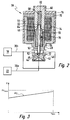
- a variable energization of the magnet winding 74 makes it possible to adapt the opening pressure of the pressure valve 38 to the speed of the internal combustion engine 10. For reasons of emissions and fuel consumption, it is desirable that the fuel pressure applied to the fuel injection devices 28 be lower at low engine speeds 10 than at high speeds. This is normally achieved by energizing the magnetic winding 74 accordingly. If the power supply to the magnet winding 74 is interrupted, for example due to a dropped connector, the opening of the pressure valve 38 can be realized by designing the geometry of the valve seat 46 accordingly, as shown in FIG. 3. The opening pressure PO of the pressure valve 38 increases with the speed n. In any case, it is ensured that the opening pressure PO of the pressure valve 38 is lower than the maximum permissible functional pressure PV max of the fuel injection devices 28.
Abstract
Description
Die Erfindung betrifft zunächst ein Kraftstoffsystem für eine Brennkraftmaschine, mit einem Kraftstoffbehälter, mit mindestens einer Kraftstoffpumpe, mit einer Kraftstoff-Sammelleitung, die von der Kraftstoffpumpe gespeist wird, mit einer Ventileinrichtung, mit der der Druck in der Kraftstoff-Sammelleitung gesteuert werden kann, und mit mindestens einer Kraftstoff-Einspritzvorrichtung, über die der Kraftstoff in einen Brennraum der Brennkraftmaschine gelangen kann.The invention first relates to a fuel system for an internal combustion engine, with a fuel tank, with at least one fuel pump, with a fuel manifold, which is fed by the fuel pump, with a valve device with which the pressure in the Fuel rail can be controlled and with at least one fuel injector through which the fuel into a combustion chamber of the internal combustion engine can reach.
Ein solches Kraftstoffsystem ist aus der DE 195 39 883 A1 bekannt. Bei dieser fördern zwei in Reihe geschaltete Pumpen den Kraftstoff aus einem Kraftstoffbehälter in eine Kraftstoff-Sammelleitung, welche gemeinhin auch als "Rail" bezeichnet wird. In der Kraftstoff-Sammelleitung wird der Kraftstoff unter relativ hohem Druck gespeichert. An die Kraftstoff-Sammelleitung sind Einspritzventile angeschlossen, die den Kraftstoff direkt in entsprechende Brennräume einspritzen.Such a fuel system is known from DE 195 39 883 A1 known. In this promote two connected in series Pump the fuel from a fuel tank into one Fuel manifold, which is commonly referred to as a "rail" referred to as. In the fuel rail, the Fuel stored under relatively high pressure. To the Fuel manifolds are injectors connected that directly into the fuel Inject combustion chambers.
Der Druck in der Kraftstoff-Sammelleitung wird durch ein Druckventil gesteuert. Je nach Ansteuerung des Druckventils wird Kraftstoff aus der Kraftstoff-Sammelleitung über eine Rückleitung in den Kraftstoffbehälter zurückgeleitet. Bei dem bekannten Kraftstoffsystem wird nach dem Abstellen der Druck in der Kraftstoff-Sammelleitung abgebaut. Aufgrund von Wärmeleitung vom Motorblock her kann es allerdings dann in dem in der Kraftstoff-Sammelleitung vorhandenen Kraftstoff zur Bildung von Dampfblasen kommen, welche das Wiederanlassen der Brennkraftmaschine erschweren. Um diesen Nachteil zu beseitigen, wird bei dem bekannten Kraftstoffsystem beim Anlassen der Brennkraftmaschine der Druck des von der ersten der beiden Kraftstoffpumpen geförderten Kraftstoffes erhöht, um gegebenenfalls vorhandene Dampfblasen möglichst schnell aus dem Kraftstoffsystem zu eliminieren. Dies benötigt jedoch eine gewisse Zeit.The pressure in the fuel rail is indicated by a Pressure valve controlled. Depending on the control of the pressure valve fuel from the fuel rail via a Return line returned to the fuel tank. at the known fuel system is switched off after the Pressure in the fuel rail reduced. by virtue of from heat conduction from the engine block, however, it can in the one in the fuel rail Fuel to form vapor bubbles which are the Difficult to restart the engine. To this Eliminating the disadvantage is in the known Fuel system when starting the internal combustion engine Pressure of the first of the two fuel pumps delivered fuel increased to, if necessary existing vapor bubbles as quickly as possible Eliminate fuel system. However, this requires one certain time.
Die vorliegende Erfindung hat die Aufgabe, ein Kraftstoffsystem der eingangs genannten Art so weiterzubilden, dass eine mit dem Kraftstoffsystem betriebene Brennkraftmaschine möglichst schnell auch im heißen Zustand gestartet werden kann.The present invention has the task of a Fuel system of the type mentioned above train that one with the fuel system operated internal combustion engine as quickly as possible also in hot state can be started.
Diese Aufgabe wird bei einem Kraftstoffsystem der eingangs genannten Art dadurch gelöst, dass die Ventileinrichtung so ausgebildet ist, dass sie mindestens beim normalen Betriebsdruck in der Kraftstoff-Sammelleitung im nicht betätigten Zustand geschlossen ist.This task is the beginning of a fuel system mentioned type in that the valve device so is trained that at least in normal Operating pressure in the fuel rail in the not actuated state is closed.
Das erfindungsgemäße Verfahren hat den Vorteil, dass sich Dampfblasen gar nicht erst bilden können, da der Druck in der Kraftstoff-Sammelleitung auf einem hohen Niveau auch bei abgestellter Brennkraftmaschine gehalten wird. Somit sind keine Maßnahmen erforderlich, um vor dem Wiederanlassen einer heißen Brennkraftmaschine eventuelle Dampfblasen aus dem Kraftstoffsystem zu entfernen. Das Anlassen einer Brennkraftmaschine, welche mit dem erfindungsgemäßen Kraftstoffsystem ausgerüstet ist, erfolgt daher sehr schnell.The method according to the invention has the advantage that Vapor bubbles cannot form at all because the pressure in the fuel rail at a high level too is held when the internal combustion engine is switched off. Consequently no action is required to take before Possible restarting a hot internal combustion engine Remove vapor bubbles from the fuel system. The Starting an internal combustion engine, which with the The fuel system according to the invention is equipped therefore very quickly.
Das Beibehalten des relativ hohen Drucks in der Kraftstoff-Sammelleitung ist bei dem erfindungsgemäßen Kraftstoffsystem sehr einfach möglich: Die Ventileinrichtung ist so aufgebaut, dass sie in ihrem nicht betätigten Ruhezustand geschlossen ist, also keine Verbindung von der Kraftstoff-Sammelleitung zurück beispielsweise zum Kraftstoffbehälter existiert. Ein solcher nicht betätigter Zustand liegt im Allgemeinen ohnehin bei abgestellter Brennkraftmaschine vor.Maintaining the relatively high pressure in the fuel rail is in the invention Very simple fuel system possible: The Valve device is designed so that it is not in your actuated hibernation is closed, so none Connection back from the fuel rail for example to the fuel tank exists. On such unactuated state is generally anyway with the internal combustion engine turned off.
Vorteilhafte Weiterbildungen der Erfindung sind in Unteransprüchen angegeben.Advantageous developments of the invention are in Subclaims specified.
In einer ersten Weiterbildung wird vorgeschlagen, dass die Ventileinrichtung elektrisch betätigt wird und im stromlosen Zustand mindestens bei normalem Druck in der Kraftstoff-Sammelleitung geschlossen ist. Elektrisch betätigte Ventileinrichtungen sind sehr einfach und preiswert herzustellen. Ein stromloser Zustand ist bei abgestellter Brennkraftmaschine darüber hinaus leicht realisierbar.In a first further training it is proposed that the Valve device is operated electrically and in de-energized state at least at normal pressure in the Fuel rail is closed. electrical actuated valve devices are very simple and inexpensive to manufacture. A de-energized state is in parked internal combustion engine also easy realizable.
Ferner ist es möglich, dass die Ventileinrichtung eine Vorspanneinrichtung umfasst, welche ein Ventilelement in Schließrichtung beaufschlagt. Eine solche Vorspanneinrichtung kann beispielsweise eine Feder umfassen. Die Betätigung des Ventilelements erfolgt also gegen die Kraft der Vorspanneinrichtung. Eine solche Ventileinrichtung baut einfach und arbeitet zuverlässig.It is also possible for the valve device to have a Preloading device which comprises a valve element in Closing direction applied. Such A biasing device can be, for example, a spring include. The valve element is thus actuated against the force of the pretensioner. Such Valve device is simple to build and works reliably.
Dabei kann die Vorspanneinrichtung so gewählt werden, dass die Ventileinrichtung im nicht betätigten Zustand öffnet, wenn der Druck in der Kraftstoff-Sammelleitung einen bestimmten Wert überschreitet. Durch diese Maßnahme wird sichergestellt, dass der Druck in der Kraftstoff-Sammelleitung bei abgestellter Brennkraftmaschine einen maximalen Wert nicht überschreiten kann. Hierdurch wird die Funktionssicherheit der Kraftstoff-Sammelleitung und angeschlossener Komponenten garantiert, da eine Erwärmung des in der Kraftstoff-Sammelleitung eingeschlossenen Kraftstoffs beispielsweise aufgrund von Wärmeleitung von der Brennkraftmaschine her und die damit verbundene Ausdehnung des eingeschlossenen Kraftstoffes nicht zu einer Beschädigung der Krafttoff-Sammelleitung oder eingeschlossener Komponenten führen kann.The pretensioning device can be selected so that the valve device opens when not actuated, when the pressure in the fuel rail is one exceeds a certain value. This measure will ensures that the pressure in the fuel rail with the internal combustion engine turned off cannot exceed the maximum value. This will make the Functional reliability of the fuel rail and connected components guaranteed because of heating of the trapped in the fuel rail Fuel, for example, due to the heat conduction of the internal combustion engine and the associated Expansion of the enclosed fuel not to one Damage to the Krafttoff manifold or included components.
Dabei ist es besonders vorteilhaft, wenn der Öffnungsdruck der Ventileinrichtung im nicht betätigten Zustand niedriger ist als der maximal zulässige Funktionsdruck der Kraftstoff-Einspritzvorrichtung. Diese Weiterbildung des erfindungsgemäßen Kraftstoffsystems trägt der Tatsache Rechnung, dass die üblichen Kraftstoff-Einspritzvorrichtungen ab einem bestimmten Druck in der Kraftstoff-Sammelleitung nicht mehr sicher betätigt werden können. Außerdem besteht die Gefahr, dass bei Überschreiten des maximal zulässigen Funktionsdruckes die Kraftstoff-Einspritzvorrichtung nicht mehr sicher schließt und somit Kraftstoff bei stehender Brennkraftmaschine in den Brennraum der Brennkraftmaschine gelangt. Durch die erfindungsgemäße Weiterbildung wird all dies verhindert.It is particularly advantageous if the opening pressure the valve device in the non-actuated state lower is the maximum permissible functional pressure Fuel injector. This training of fuel system according to the invention bears the fact Bill that the usual fuel injectors from a certain pressure in the Fuel manifold can no longer be operated safely can. There is also a risk that if exceeded the maximum permissible functional pressure the fuel injector no longer closes securely and therefore Fuel with the internal combustion engine stopped Combustion chamber of the internal combustion engine arrives. Through the Further development according to the invention prevents all of this.
Denkbar ist auch, dass der Öffnungsdruck der Ventileinrichtung bei hoher Drehzahl der Brennkraftmaschine höher ist als bei geringer Drehzahl der Brennkraftmaschine. Aufgrund dieser Maßnahme wird wiederum der Tatsache Rechnung getragen, dass es für einen verbrauchs- und emissionsoptimalen Betrieb der Brennkraftmaschine günstig ist, wenn der Druck des Kraftstoffes an der Kraftstoff-Einspritzvorrichtung bei geringer Drehzahl der Brennkraftmaschine eher niedrig ist und bei hoher Drehzahl der Brennkraftmaschine eher hoch ist. Der Öffnungsdruck der Ventileinrichtung sorgt so für einen dem jeweiligen Betriebszustand der Brennkraftmaschine entsprechenden Druck in der Kraftstoff-Sammelleitung.It is also conceivable that the opening pressure of the Valve device at high engine speed is higher than at low engine speed. Because of this measure, the fact becomes Taken into account that it is for a consumption and Low-emission operation of the internal combustion engine cheap is when the pressure of the fuel at the fuel injector at low speed the Internal combustion engine is rather low and at high speed the internal combustion engine is rather high. The opening pressure of the Valve device ensures that each one Operating state of the internal combustion engine corresponding pressure in the fuel rail.
Die Erfindung betrifft auch eine Brennkraftmaschine, insbesondere für Kraftfahrzeuge, welche ein Kraftstoffsystem umfasst mit einem Kraftstoffbehälter, mit mindestens einer Kraftstoffpumpe, mit einer Kraftstoff-Sammelleitung, die von der Kraftstoffpumpe gespeist wird, mit einer Ventileinrichtung, mit der der Druck in der Kraftstoff-Sammelleitung gesteuert werden kann, und mit mindestens einer Kraftstoff-Einspritzvorrichtung, über die der Kraftstoff in einen Brennraum der Brennkraftmaschine gelangen kann.The invention also relates to an internal combustion engine, especially for motor vehicles, which a Fuel system includes with a fuel tank, with at least one fuel pump, with a fuel manifold, which is fed by the fuel pump, with a valve device with which the pressure in the Fuel rail can be controlled and with at least one fuel injector through which the fuel into a combustion chamber of the internal combustion engine can reach.
Um bei einer solchen Brennkraftmaschine den Heißstart, also das Wiederanlassen der heißen Brennkraftmaschine, zu beschleunigen, wird vorgeschlagen, dass die Ventileinrichtung des Kraftstoffsystems so ausgebildet ist, dass sie mindestens bei normalem Druck in der Kraftstoff-Sammelleitung im nicht bestätigten Zustand geschlossen ist. Im Hinblick auf die Vorteile einer solchen Brennkraftmaschine wird auf die obigen Ausführungen verwiesen.To get the hot start in such an internal combustion engine, that is restarting the hot engine, too accelerate, it is suggested that the Valve device of the fuel system is designed that they are at least at normal pressure in the fuel rail is closed in the unconfirmed state. With regard to the advantages of such Internal combustion engine is based on the above directed.
Die Erfindung betrifft ferner ein Verfahren zum Betreiben einer Brennkraftmaschine insbesondere für Kraftfahrzeuge, bei dem der Kraftstoff aus einem Kraftstoffbehälter über mindestens eine Kraftstoffpumpe in eine Kraftstoff-Sammelleitung und von dort über eine Kraftstoff-Einspritzvorrichtung in einen Brennraum der Brennkraftmaschine gefördert wird und bei dem der Druck in der Kraftstoff-Sammelleitung über eine Ventileinrichtung gesteuert wird.The invention further relates to a method for operating an internal combustion engine, in particular for motor vehicles, where the fuel comes from a fuel tank at least one fuel pump in a fuel rail and from there via a fuel injector into a combustion chamber of the Internal combustion engine is promoted and in which the pressure in the fuel rail via a valve device is controlled.
Um bei einem solchen Verfahren sicherzustellen, dass die Brennkraftmaschine auch im heißen Zustand möglichst schnell angelassen werden kann, wird vorgeschlagen, dass die Ventileinrichtung mindestens bei normalem Druck in der Kraftstoff-Sammelleitung im nicht betätigten Zustand geschlossen ist. Auch hier wird im Hinblick auf die Vorteile auf die obigen Ausführungen verwiesen.In order to ensure that the Internal combustion engine as quickly as possible, even when hot can be started, it is suggested that the Valve device at least at normal pressure in the Fuel manifold when not operated closed is. Again, with regard to the Advantages referred to the above explanations.
Nachfolgend wird ein bevorzugtes Ausführungsbeispiel der Erfindung unter Bezugnahme auf die beiliegende Zeichnung im Detail erläutert. In der Zeichnung zeigen:
- Fig. 1:
- ein Blockschaltbild einer Brennkraftmaschine mit einem Kraftstoffsystem mit einer Ventileinrichtung;
- Fig. 2:
- einen teilweisen Schnitt durch die Ventileinrichtung von Fig. 1; und
- Fig. 3:
- ein Diagramm, in dem der Öffnungsdruck der Ventileinrichtung von Fig. 2 über der Drehzahl der Brennkraftmaschine aufgetragen ist.
- Fig. 1:
- a block diagram of an internal combustion engine with a fuel system with a valve device;
- Fig. 2:
- a partial section through the valve device of Fig. 1; and
- Fig. 3:
- a diagram in which the opening pressure of the valve device of Fig. 2 is plotted against the speed of the internal combustion engine.
In Fig. 1 trägt eine Brennkraftmaschine insgesamt das
Bezugszeichen 10. Sie ist im vorliegenden
Ausführungsbeispiel nur symbolhaft durch eine
strichpunktierte Linie angedeutet. Die Brennkraftmaschine
10 umfasst wiederum ein Kraftstoffsystem 12. In Fig. 1, an internal combustion engine carries this
Zu diesem gehört ein Kraftstoffbehälter 14, aus dem eine
elektrische Kraftstoffpumpe 16 Kraftstoff in eine
Kraftstoffverbindung 18 fördert. Über einen Filter 20
gelangt der Kraftstoff zu einer Hochdruck-Kraftstoffpumpe
22. Diese wird auf hier nicht näher dargestellte Art und
Weise direkt von einer Kurbelwelle der Brennkraftmaschine
10 angetrieben. Der Druck in der Kraftstoffverbindung 18
wird durch einen Niederdruckregler 24 eingestellt.This includes a
Die Hochdruck-Kraftstoffpumpe 22 komprimiert den von der
elektrischen Kraftstoffpumpe 16 vorverdichteten Kraftstoff
weiter und fördert ihn in eine Kraftstoff-Sammelleitung 26.
Diese wird gemeinhin auch als "Rail" bezeichnet. In ihr ist
der Kraftstoff während des Betriebs der Brennkraftmaschine
10 unter sehr hohem Druck, bis ungefähr 120 bar,
gespeichert. An die Kraftstoff-Sammelleitung 26 sind
mehrere Kraftstoff-Einspritzvorrichtungen 28 angeschlossen.
Bei diesen handelt es sich vorliegend um Injektoren, welche
den Kraftstoff direkt in entsprechende Brennräume 30
einspritzen. Bei der dargestellten Brennkraftmaschine 10
handelt es sich also um eine solche mit Kraftstoff-Direkteinspritzung.
Beim Kraftstoff kann es sich um Benzin
ebenso wie um Diesel handeln.The high
Der Druck in der Kraftstoff-Sammelleitung 26 wird von einem
Drucksensor 32 erfasst. Dieser liefert Signale an ein
Steuer- und Regelgerät 34. Die Kraftstoff-Sammelleitung 26
ist über eine Kraftstoffverbindung 36 mit der
Kraftstoffverbindung 18 verbunden. In der
Kraftstoffverbindung 36 ist ein Druckventil 38 angeordnet,
dessen genaue Ausgestaltung weiter unten erläutert wird.
Das Druckventil 38 wird vom Steuer- und Regelgerät 34
angesteuert.The pressure in the
Das Druckventil 38 ist im Einzelnen wie folgt aufgebaut
(vgl. Fig. 2): The
Fig. 2 zeigt einen zylindrischen Ventilkörper 40, der in
Einbaulage in eine zylindrische Ausnehmung eines in Fig. 2
nicht dargestellten Aufnahmeteils eingesetzt und an diesem
befestigt ist. An diesem Aufnahmeteil sind auch die
Anschlüsse für die Kraftstoffverbindung 36 vorhanden. Der
zwischen dem Druckventil 38 und der Hochdruck-Kraftstoffpumpe
22 liegende Bereich der
Kraftstoffverbindung trägt dabei das Bezugszeichen 36a,
wohingegen der zur Kraftstoffverbindung 18 hin zeigende
Bereich das Bezugszeichen 36b trägt.Fig. 2 shows a
Der Ventilkörper 40 ist zweiteilig aufgebaut. Im in Fig. 2
unteren Teil 42 ist eine zum Ventilkörper 40 koaxiale
Durchgangsbohrung 44 vorhanden, die sich in Fig. 2 nach
oben hin konisch erweitert. Die konische Erweiterung (ohne
Bezugszeichen) bildet einen Ventilsitz für eine Ventilkugel
46. Im in Fig. 2 oberen Teil 48 des Ventilkörpers 40 ist
eine ebenfalls zum Ventilkörper 40 koaxiale
Durchgangsbohrung 50 vorhanden, von der zwei radial
verlaufende Bohrungen 52 abzweigen. Die Durchgangsbohrung
44 im unteren Teil 42 des Ventilkörpers 40 ist mit dem
Einlass des Druckventils 38 und somit in Einbaulage mit der
Leitung 36a verbunden, wohingegen die radialen Bohrungen 52
zu einem Auslass des Druckventils 38 und somit in
Einbaulage zur Leitung 36b führen.The
In der zentrischen Durchgangsbohrung 50 ist ein
Ventilstößel 54 angeordnet, an dessen in Fig. 2 oberem
Endabschnitt ein Magnetanker 56 befestigt ist. Der
Ventilstößel 54 ist im Bereich der Durchgangsbohrung 50 in
einer Gleitbuchse (nicht dargestellt) geführt. Im oberen
Bereich des oberen Teils 48 des Ventilkörpers 40 ist auf
der äußeren Mantelfläche des oberen Teils 48 eine Hülse 58
befestigt, die mit ihrem in Fig. 3 oberen Bereich wiederum
mit einem Gehäusekörper 60 verbunden ist. In diesem ist ein
in Fig. 2 nach unten offenes Sackloch 62 vorhanden. In the central through
Am in Fig. 2 unteren Ende des Sacklochs 62 ist in dieses
ein Führungsring 64 eingesetzt. In diesem ist das obere
Ende 66 des Ventilstößels 54 gleitend geführt. Das obere
Ende 66 des Ventilstößels 54 wird von einer Druckfeder 68
beaufschlagt, die sich an der Basis des Sacklochs 62 im
Gehäusekörper 60 abstützt. Über die Druckfeder 68 und den
Ventilstößel 54 wird letztlich die Ventilkugel 46 gegen den
Ventilsitz in der Durchgangsbohrung 44 im unteren Teil 42
des Ventilkörpers 40 gedrückt.At the bottom in Fig. 2 the
Am Gehäusekörper 60 ist außen ein Haltering 70 befestigt.
Der Haltering 70 ragt radial vom Gehäusekörper 60 ab und
ist insgesamt koaxial zu diesem. An dem radial äußeren
Randbereich des Halterings 70 sind zwei Bügelelemente 72
befestigt, die eine Magnetwicklung 74 umgreifen. Der obere
Bereich des Gehäusekörpers 60, der Haltering 70 und die
Bügelelemente 72 sind mit Kunststoff 76 umspritzt.A retaining
Wenn die Brennkraftmaschine 10 eingeschaltet ist, wird der
Druck in der Kraftstoff-Sammelleitung 26 vom Drucksensor 32
erfasst und über das Steuer- und Regelgerät 34 das
Druckventil 38 so angesteuert, dass in der Kraftstoff-Sammelleitung
26 ein gewünschter Druck herrscht. Dabei
führt eine Bestromung der Magnetwicklung 74 zu einer auf
den Magnetanker 56 in Richtung des Pfeiles 78 wirkenden
Kraft. Diese wird der Schließkraft der Druckfeder 68
überlagert. Somit wird die Ventilkugel 46 bei einer
Bestromung der Magnetwicklung 74 mit geringerer Kraft gegen
den Ventilsitz gedrückt, wodurch der Öffnungsdruck des
Druckventils 38 variiert werden kann.When the
Fließt kein Strom durch die Magnetwicklung 74, wird die
Ventilkugel 46 mit der vollen Kraft der Druckfeder 68 gegen
den Ventilsitz gedrückt. In diesem Fall ist also das
Druckventil 38 geschlossen. Die Druckfeder 68 ist
allerdings so bemessen, dass die Ventilkugel 46 gegen die
Kraft der Druckfeder 68 vom Ventilsitz abhebt, wenn der
Druck in der Kraftstoff-Sammelleitung 26 einen maximal
zulässigen Wert überschreitet. Auf diese Weise wird
sichergestellt, dass dann, wenn die Magnetwicklung 74 nicht
mehr bestromt werden kann, weil beispielsweise die
Stromversorgung durch einen Defekt unterbrochen ist, der
Druck in der Kraftstoff-Sammelleitung 26 einen maximal
zulässigen Wert nicht überschreitet.If no current flows through the magnetic winding 74, the
Somit wird die Funktionssicherheit der Kraftstoff-Einspritzvorrichtungen
28, welche nur bis zu einem
bestimmten maximalen Druck sicher arbeiten können,
gewährleistet. Ferner wird sichergestellt, dass es bei
abgestellter Brennkraftmaschine in dem in der Kraftstoff-Sammelleitung
26 eingeschlossenen Kraftstoffvolumen
aufgrund von Wärmeleitung innerhalb der Kraftstoff-Sammelleitung
26 nicht zu einem unzulässigen Druckanstieg
kommen kann, welcher beispielsweise zu einer ungewollten
Leckage der Kraftstoff-Einspritzvorrichtungen 28 in die
Brennräume 30 hinein führen könnte.This ensures the functional reliability of the
Bei abgestellter Brennkraftmaschine 10 ist die
Magnetwicklung 74 stromlos. Wie bereits ausgeführt wurde,
wird in diesem Fall die Ventilkugel 46 mit der maximalen
Kraft der Druckfeder 68 gegen den Ventilsitz gedrückt. Das
Druckventil 38 ist somit geschlossen und das in der
Kraftstoff-Sammelleitung 26 vorhandene Kraftstoffvolumen
nach außen hin abgeschlossen. Der in der Kraftstoff-Sammelleitung
26 vorhandene Druck wird somit bei
abgestellter Brennkraftmaschine 10 nicht abgelassen,
sondern beibehalten.When the
Durch eine variable Bestromung der Magnetwicklung 74 ist es
möglich, den Öffnungsdruck des Druckventils 38 an die
Drehzahl der Brennkraftmaschine 10 anzupassen. Aus
Emissions- und Verbrauchsgründen ist es gewünscht, dass der
an den Kraftstoff-Einspritzvorrichtungen 28 anliegende
Kraftstoffdruck bei niedrigen Drehzahlen der
Brennkraftmaschine 10 niedriger ist als bei hohen
Drehzahlen. Dies wird normalerweise durch eine
entsprechende Bestromung der Magnetwicklung 74 erreicht.
Ist die Stromversorgung zu der Magnetwicklung 74
beispielsweise aufgrund eines abgefallenen Steckers
unterbrochen, kann durch eine entsprechende Gestaltung der
Geometrie des Ventilsitzes der Ventilkugel 46 dennoch eine
solche Öffnungscharakteristik des Druckventils 38
realisiert werden, wie sie in Fig. 3 dargestellt ist. Dabei
steigt der Öffnungsdruck PO des Druckventils 38 mit der
Drehzahl n. In jedem Falle ist dabei sichergestellt, dass
der Öffnungsdruck PO des Druckventils 38 kleiner ist als
der maximal zulässige Funktionsdruck PVmax der Kraftstoff-Einspritzvorrichtungen
28.A variable energization of the magnet winding 74 makes it possible to adapt the opening pressure of the
Claims (8)
Applications Claiming Priority (2)
| Application Number | Priority Date | Filing Date | Title |
|---|---|---|---|
| DE10125982 | 2001-05-29 | ||
| DE2001125982 DE10125982A1 (en) | 2001-05-29 | 2001-05-29 | Fuel system for an internal combustion engine, internal combustion engine, and method for operating an internal combustion engine |
Publications (3)
| Publication Number | Publication Date |
|---|---|
| EP1262659A2 true EP1262659A2 (en) | 2002-12-04 |
| EP1262659A3 EP1262659A3 (en) | 2004-12-22 |
| EP1262659B1 EP1262659B1 (en) | 2010-08-04 |
Family
ID=7686419
Family Applications (1)
| Application Number | Title | Priority Date | Filing Date |
|---|---|---|---|
| EP20020011016 Expired - Lifetime EP1262659B1 (en) | 2001-05-29 | 2002-05-17 | Fuel system for an internal combustion engine |
Country Status (3)
| Country | Link |
|---|---|
| EP (1) | EP1262659B1 (en) |
| JP (1) | JP3836399B2 (en) |
| DE (2) | DE10125982A1 (en) |
Cited By (3)
| Publication number | Priority date | Publication date | Assignee | Title |
|---|---|---|---|---|
| EP1491761A1 (en) * | 2003-06-27 | 2004-12-29 | Denso Corporation | Common rail type fuel injection system |
| EP1643111A1 (en) * | 2004-09-29 | 2006-04-05 | Denso Corporation | Common rail fuel injection system |
| WO2006100141A1 (en) * | 2005-03-21 | 2006-09-28 | Robert Bosch Gmbh | Fuel injection device for an internal combusting engine |
Families Citing this family (4)
| Publication number | Priority date | Publication date | Assignee | Title |
|---|---|---|---|---|
| DE10342550A1 (en) * | 2003-09-15 | 2005-04-07 | Robert Bosch Gmbh | Pressure control valve for storage fuel injection system |
| DE102005001577B4 (en) * | 2005-01-13 | 2017-04-06 | Robert Bosch Gmbh | Method and device for controlling an internal combustion engine |
| DE102007053248B4 (en) | 2007-11-08 | 2009-07-09 | Continental Automotive Gmbh | Fuel system for controlling an internal combustion engine and method for controlling such a fuel system |
| JP4922906B2 (en) | 2007-12-10 | 2012-04-25 | 日立オートモティブシステムズ株式会社 | High pressure fuel supply device and control device for internal combustion engine |
Citations (5)
| Publication number | Priority date | Publication date | Assignee | Title |
|---|---|---|---|---|
| US5558068A (en) | 1994-05-31 | 1996-09-24 | Zexel Corporation | Solenoid valve unit for fuel injection apparatus |
| DE19539883A1 (en) | 1995-05-26 | 1996-11-28 | Bosch Gmbh Robert | Fuel supply system for IC engine |
| US6024064A (en) | 1996-08-09 | 2000-02-15 | Denso Corporation | High pressure fuel injection system for internal combustion engine |
| DE19936287A1 (en) | 1999-08-02 | 2001-02-22 | Bosch Gmbh Robert | I.c. engine variable pressure fuel feed module control system has return feed that can be closed by a switchable actuator |
| EP1092863A2 (en) | 1999-10-15 | 2001-04-18 | Robert Bosch Gmbh | Pressure regulating valve for an accumulator-type fuel injection system for internal combustion engines |
Family Cites Families (2)
| Publication number | Priority date | Publication date | Assignee | Title |
|---|---|---|---|---|
| DE19742180C2 (en) * | 1997-09-24 | 1999-07-08 | Siemens Ag | Injection system for an internal combustion engine and method for regulating an injection system |
| DE19927804A1 (en) * | 1999-06-18 | 2000-12-28 | Bosch Gmbh Robert | Fuel supply system for internal combustion engine has relief device that is connected to pressure line and contains mechanically or hydraulically switchable artificial load |
-
2001
- 2001-05-29 DE DE2001125982 patent/DE10125982A1/en not_active Ceased
-
2002
- 2002-05-17 DE DE50214563T patent/DE50214563D1/en not_active Expired - Lifetime
- 2002-05-17 EP EP20020011016 patent/EP1262659B1/en not_active Expired - Lifetime
- 2002-05-28 JP JP2002154234A patent/JP3836399B2/en not_active Expired - Fee Related
Patent Citations (5)
| Publication number | Priority date | Publication date | Assignee | Title |
|---|---|---|---|---|
| US5558068A (en) | 1994-05-31 | 1996-09-24 | Zexel Corporation | Solenoid valve unit for fuel injection apparatus |
| DE19539883A1 (en) | 1995-05-26 | 1996-11-28 | Bosch Gmbh Robert | Fuel supply system for IC engine |
| US6024064A (en) | 1996-08-09 | 2000-02-15 | Denso Corporation | High pressure fuel injection system for internal combustion engine |
| DE19936287A1 (en) | 1999-08-02 | 2001-02-22 | Bosch Gmbh Robert | I.c. engine variable pressure fuel feed module control system has return feed that can be closed by a switchable actuator |
| EP1092863A2 (en) | 1999-10-15 | 2001-04-18 | Robert Bosch Gmbh | Pressure regulating valve for an accumulator-type fuel injection system for internal combustion engines |
Cited By (6)
| Publication number | Priority date | Publication date | Assignee | Title |
|---|---|---|---|---|
| EP1491761A1 (en) * | 2003-06-27 | 2004-12-29 | Denso Corporation | Common rail type fuel injection system |
| US6895936B2 (en) | 2003-06-27 | 2005-05-24 | Denso Corporation | Common rail type fuel injection system |
| EP1643111A1 (en) * | 2004-09-29 | 2006-04-05 | Denso Corporation | Common rail fuel injection system |
| US7204233B2 (en) | 2004-09-29 | 2007-04-17 | Denso Corporation | Common rail fuel injection system |
| WO2006100141A1 (en) * | 2005-03-21 | 2006-09-28 | Robert Bosch Gmbh | Fuel injection device for an internal combusting engine |
| US7574297B2 (en) | 2005-03-21 | 2009-08-11 | Robert Bosch Gmbh | Fuel injection device for an internal combustion engine |
Also Published As
| Publication number | Publication date |
|---|---|
| EP1262659B1 (en) | 2010-08-04 |
| DE10125982A1 (en) | 2002-12-12 |
| JP2003028027A (en) | 2003-01-29 |
| DE50214563D1 (en) | 2010-09-16 |
| JP3836399B2 (en) | 2006-10-25 |
| EP1262659A3 (en) | 2004-12-22 |
Similar Documents
| Publication | Publication Date | Title |
|---|---|---|
| DE19640826B4 (en) | Storage fuel injection device and pressure control device therefor | |
| DE10064055B4 (en) | Control device for high pressure fuel pump and for direct injection engine | |
| DE19742180C2 (en) | Injection system for an internal combustion engine and method for regulating an injection system | |
| DE10144895B4 (en) | Fuel supply device with variable delivery | |
| WO1996019659A1 (en) | Process for reducing the fuel pressure in a fuel injection system | |
| EP2207955A1 (en) | Fuel overflow valve for a fuel injection system, and fuel injection system having a fuel overflow valve | |
| DE19630938C5 (en) | Fuel supply with a flow control valve and flow control valve | |
| EP1348072B1 (en) | Method, computer program and control and/or regulation device for operating an internal combustion engine, and corresponding internal combustion engine | |
| DE102005028931B4 (en) | Fuel supply system for an internal combustion engine | |
| DE19545162B4 (en) | Fuel injection device with spring-biased control valve | |
| DE10320592A1 (en) | Feed pump, in particular high-pressure fuel pump for an internal combustion engine | |
| WO2001052916A2 (en) | Injection device and method for injecting a fluid | |
| DE102012107764A1 (en) | Common Rail System | |
| EP1327766B1 (en) | Method, computer programme and control and/or regulation device for operating an internal combustion engine, and internal combustion engine | |
| EP1262659A2 (en) | Fuel system for an internal combustion engine | |
| EP1799999B1 (en) | Fuel system for an internal combustion engine | |
| EP1262658B1 (en) | Fuel system for supplying fuel for an internal combustion engine | |
| DE102005000639A1 (en) | Pressure modulated common rail injector and injection system | |
| DE102005061362B3 (en) | Pressure control valve for injection system of multi-cylinder internal combustion engine, has closing body provided in non-controlled condition of actuator in closing position, where force acting on body is changed by controlling actuator | |
| DE102010042251A1 (en) | Fuel injector for use as common-rail injector in internal combustion engine, has injector housing, which encloses high pressure chamber that stays in connection with high pressure source | |
| WO2005001280A1 (en) | Fuel-injection system with reduced pressure pulsations in the return rail | |
| EP2204570B1 (en) | Fuel injector | |
| DE10261414A1 (en) | Fuel injection system | |
| DE10124510B4 (en) | A method for driving a solenoid valve controlled fuel pump of an internal combustion engine | |
| DE102005045064A1 (en) | Injector for high-pressure injection |
Legal Events
| Date | Code | Title | Description |
|---|---|---|---|
| PUAI | Public reference made under article 153(3) epc to a published international application that has entered the european phase |
Free format text: ORIGINAL CODE: 0009012 |
|
| AK | Designated contracting states |
Kind code of ref document: A2 Designated state(s): AT BE CH CY DE DK ES FI FR GB GR IE IT LI LU MC NL PT SE TR |
|
| AX | Request for extension of the european patent |
Free format text: AL;LT;LV;MK;RO;SI |
|
| PUAL | Search report despatched |
Free format text: ORIGINAL CODE: 0009013 |
|
| AK | Designated contracting states |
Kind code of ref document: A3 Designated state(s): AT BE CH CY DE DK ES FI FR GB GR IE IT LI LU MC NL PT SE TR |
|
| AX | Request for extension of the european patent |
Extension state: AL LT LV MK RO SI |
|
| 17P | Request for examination filed |
Effective date: 20050622 |
|
| AKX | Designation fees paid |
Designated state(s): DE FR GB IT |
|
| 17Q | First examination report despatched |
Effective date: 20070830 |
|
| GRAP | Despatch of communication of intention to grant a patent |
Free format text: ORIGINAL CODE: EPIDOSNIGR1 |
|
| GRAS | Grant fee paid |
Free format text: ORIGINAL CODE: EPIDOSNIGR3 |
|
| GRAA | (expected) grant |
Free format text: ORIGINAL CODE: 0009210 |
|
| AK | Designated contracting states |
Kind code of ref document: B1 Designated state(s): DE FR GB IT |
|
| REG | Reference to a national code |
Ref country code: GB Ref legal event code: FG4D Free format text: NOT ENGLISH |
|
| REF | Corresponds to: |
Ref document number: 50214563 Country of ref document: DE Date of ref document: 20100916 Kind code of ref document: P |
|
| PLBE | No opposition filed within time limit |
Free format text: ORIGINAL CODE: 0009261 |
|
| STAA | Information on the status of an ep patent application or granted ep patent |
Free format text: STATUS: NO OPPOSITION FILED WITHIN TIME LIMIT |
|
| 26N | No opposition filed |
Effective date: 20110506 |
|
| REG | Reference to a national code |
Ref country code: DE Ref legal event code: R097 Ref document number: 50214563 Country of ref document: DE Effective date: 20110506 |
|
| PGFP | Annual fee paid to national office [announced via postgrant information from national office to epo] |
Ref country code: GB Payment date: 20140520 Year of fee payment: 13 |
|
| PGFP | Annual fee paid to national office [announced via postgrant information from national office to epo] |
Ref country code: IT Payment date: 20140520 Year of fee payment: 13 Ref country code: FR Payment date: 20140516 Year of fee payment: 13 |
|
| PGFP | Annual fee paid to national office [announced via postgrant information from national office to epo] |
Ref country code: DE Payment date: 20140724 Year of fee payment: 13 |
|
| REG | Reference to a national code |
Ref country code: DE Ref legal event code: R119 Ref document number: 50214563 Country of ref document: DE |
|
| GBPC | Gb: european patent ceased through non-payment of renewal fee |
Effective date: 20150517 |
|
| PG25 | Lapsed in a contracting state [announced via postgrant information from national office to epo] |
Ref country code: IT Free format text: LAPSE BECAUSE OF NON-PAYMENT OF DUE FEES Effective date: 20150517 |
|
| REG | Reference to a national code |
Ref country code: FR Ref legal event code: ST Effective date: 20160129 |
|
| PG25 | Lapsed in a contracting state [announced via postgrant information from national office to epo] |
Ref country code: GB Free format text: LAPSE BECAUSE OF NON-PAYMENT OF DUE FEES Effective date: 20150517 Ref country code: DE Free format text: LAPSE BECAUSE OF NON-PAYMENT OF DUE FEES Effective date: 20151201 |
|
| PG25 | Lapsed in a contracting state [announced via postgrant information from national office to epo] |
Ref country code: FR Free format text: LAPSE BECAUSE OF NON-PAYMENT OF DUE FEES Effective date: 20150601 |