EP1261069A1 - Dispositif de soulagement de contraintes de traction - Google Patents
Dispositif de soulagement de contraintes de traction Download PDFInfo
- Publication number
- EP1261069A1 EP1261069A1 EP02011205A EP02011205A EP1261069A1 EP 1261069 A1 EP1261069 A1 EP 1261069A1 EP 02011205 A EP02011205 A EP 02011205A EP 02011205 A EP02011205 A EP 02011205A EP 1261069 A1 EP1261069 A1 EP 1261069A1
- Authority
- EP
- European Patent Office
- Prior art keywords
- strain relief
- flat conductor
- relief device
- conductor
- flexible flat
- Prior art date
- Legal status (The legal status is an assumption and is not a legal conclusion. Google has not performed a legal analysis and makes no representation as to the accuracy of the status listed.)
- Withdrawn
Links
- 239000004020 conductor Substances 0.000 claims abstract description 125
- 238000009826 distribution Methods 0.000 claims description 3
- 239000011888 foil Substances 0.000 abstract description 5
- RYGMFSIKBFXOCR-UHFFFAOYSA-N Copper Chemical compound [Cu] RYGMFSIKBFXOCR-UHFFFAOYSA-N 0.000 description 13
- 229910052802 copper Inorganic materials 0.000 description 13
- 239000010949 copper Substances 0.000 description 13
- 230000000694 effects Effects 0.000 description 8
- 239000004033 plastic Substances 0.000 description 6
- 238000001746 injection moulding Methods 0.000 description 2
- 230000002427 irreversible effect Effects 0.000 description 2
- 239000004642 Polyimide Substances 0.000 description 1
- 239000000853 adhesive Substances 0.000 description 1
- 230000001070 adhesive effect Effects 0.000 description 1
- 230000015572 biosynthetic process Effects 0.000 description 1
- 238000007796 conventional method Methods 0.000 description 1
- 230000008878 coupling Effects 0.000 description 1
- 238000010168 coupling process Methods 0.000 description 1
- 238000005859 coupling reaction Methods 0.000 description 1
- 238000002788 crimping Methods 0.000 description 1
- 238000013461 design Methods 0.000 description 1
- 238000011161 development Methods 0.000 description 1
- 230000018109 developmental process Effects 0.000 description 1
- 238000010586 diagram Methods 0.000 description 1
- 238000002347 injection Methods 0.000 description 1
- 239000007924 injection Substances 0.000 description 1
- 238000005304 joining Methods 0.000 description 1
- 239000002650 laminated plastic Substances 0.000 description 1
- 238000004519 manufacturing process Methods 0.000 description 1
- 239000002184 metal Substances 0.000 description 1
- 229910052751 metal Inorganic materials 0.000 description 1
- 238000000034 method Methods 0.000 description 1
- 239000002985 plastic film Substances 0.000 description 1
- 229920006255 plastic film Polymers 0.000 description 1
- 229920003055 poly(ester-imide) Polymers 0.000 description 1
- 229920001721 polyimide Polymers 0.000 description 1
- 238000005476 soldering Methods 0.000 description 1
- 238000012549 training Methods 0.000 description 1
- 230000007704 transition Effects 0.000 description 1
Images


Classifications
-
- H—ELECTRICITY
- H01—ELECTRIC ELEMENTS
- H01R—ELECTRICALLY-CONDUCTIVE CONNECTIONS; STRUCTURAL ASSOCIATIONS OF A PLURALITY OF MUTUALLY-INSULATED ELECTRICAL CONNECTING ELEMENTS; COUPLING DEVICES; CURRENT COLLECTORS
- H01R13/00—Details of coupling devices of the kinds covered by groups H01R12/70 or H01R24/00 - H01R33/00
- H01R13/58—Means for relieving strain on wire connection, e.g. cord grip, for avoiding loosening of connections between wires and terminals within a coupling device terminating a cable
- H01R13/582—Means for relieving strain on wire connection, e.g. cord grip, for avoiding loosening of connections between wires and terminals within a coupling device terminating a cable the cable being clamped between assembled parts of the housing
- H01R13/5825—Means for relieving strain on wire connection, e.g. cord grip, for avoiding loosening of connections between wires and terminals within a coupling device terminating a cable the cable being clamped between assembled parts of the housing the means comprising additional parts captured between housing parts and cable
Definitions
- the present invention relates to a strain relief device for flexible Flat conductor.
- strain relief devices in connectors provided that serve one with contact elements in the connector connected conductor to the housing of the connector attach so that there is a pull on the conductor from the housing of the connector and thereby a mechanical load the contact elements with possible loss of contact is avoided.
- strain relief for connectors takes place for flexible flat conductors in that there are holes in the flexible flat conductors be punched through the corresponding tenon one with the flexible Connect flat conductor connected connector, so that on the flexible flat conductors exerted tensile forces over the edges of the punched holes be transferred to the pin in the connector housing.
- a strain relief device is for strain relief a given flexible flat conductor provided therein, the has a carrier film and therein a given distribution of conductor tracks.
- the flexible flat conductor can in particular be FPC and / or FFC flat conductors, which among other things Decide that the thickness of the conductor tracks is essential for FPC flat conductors is lower than with FFC flat conductors.
- the strain relief device has a first holding element and second holding element, which for fastening a flat conductor between an open position for inserting the flat conductor and a holding position are movable and can be locked against each other in the holding position, a section of the flexible flat conductor between the two holding elements can be included.
- the holding elements can be in the open position already connected or as two separate, there are elements to be merged.
- Locking appropriate devices for example snap elements, be provided, but not necessarily on the holding elements themselves must be attached.
- a projection and are on the first holding element a corresponding depression is formed on the second holding element, that when enclosing the flexible flat conductor between the first and the second holding element and when the same moves into the holding position and mutual locking an area of the carrier film that does not Has conductor tracks or only edge areas of conductor tracks, for strain relief pressable from the projection into the recess and at the other Edge can be clamped.
- the holding elements are at or after the connection with the flexible flat conductor to exercise the necessary Clamping force locked against each other or connected to each other, for what Devices corresponding to the holding elements for locking or Connection can be provided. Because jamming in non-conductive Areas or only marginal areas of conductor tracks As a rule, the lead does not extend across the entire width of the flexible Extend flat conductor.
- the projection on the first holding element and the corresponding one Depth on the second holding element depending on the Thickness of the carrier film of the flexible flat conductor must be dimensioned such that a corresponding clamping effect occurs at the edge.
- a corresponding clamping effect occurs at the edge.
- the invention is therefore suitable Strain relief devices especially for flexible flat conductors, the carrier foils of the same thickness but different conductor tracks Have thickness, especially for FPC and FFC flat conductors.
- the friction between can make an additional contribution to strain relief the projection and the carrier film lying against it arise.
- strain relief devices according to the invention are also made of plastic, e.g. by injection molding, very simple and inexpensive produced.
- the projection and the recess are formed so that the Carrier film of the flexible flat conductor when it is clamped by the Edge of the recess is scored.
- the notch is created here by plastic deformation of the carrier foil of the flat conductor, which is usually made of plastic or plastic laminates containing e.g. polyester or polyimides.
- the edge of the depression is preferred for a particularly good clamping effect edge-shaped, the angle, that is enclosed by the surfaces forming the edge, about 90 ° is. Due to the edge-shaped design of the edge, the pinching takes place over a comparatively small area, which means that not only the particularly good clamping effect is effected, but also the training a notch-like deformation in the carrier film is favored. In addition, there is a particularly effective form fit between the edge-shaped edge and the notch-like deformation the carrier film.
- the projection and the recess should preferably be designed in this way be that when the flexible flat conductor is pinched, its carrier film only is scored and / or stretched, the stretch being a act at least partially irreversible deformation of the carrier film can.
- the projection and the recess should preferably not be so be designed such that when the flat conductor is pinched, holes or cracks arise in the carrier film, which e.g. if the gap between Projection and edge of the recess or a tapered tip Lead could occur. This will result in tensile loads less easily damage in the carrier film.
- the projection is preferably dome-shaped, so that damage the carrier foil of the flexible flat conductor is largely excluded is.
- the carrier film can be one inserted flexible flat conductor also over a large area on the projection concern, which makes an additional contribution to strain relief achieved by the friction between the projection and the adjacent carrier film becomes.
- the projection can preferably be in the form of a truncated cone be, with particular preference the truncated cone on its narrow, free end has strongly rounded edges.
- the truncated cone becomes a particularly good clamping effect achieved at the edge of the recess, even if the thickness of the carrier film is around their mean fluctuates more.
- each case at least three projections and three corresponding depressions are provided.
- the projections there it is not necessary for all the projections to be formed on the first holding element, rather, individual projections can also be on the second holding element and the corresponding depressions are formed in the first holding element his.
- the strain relief by the invention Strain relief device absorb higher tensile forces because the forces be distributed over three marginal areas.
- the protrusions also absorb torques, so that not too wide Flat conductors also secure against twisting the flat conductor in the Strain relief device is achieved.
- one is expected to be essentially transverse to the direction Zuges preferably at least two projections and corresponding Provided recesses in the holding elements, again here not all protrusions in the first holding element and all depressions in the second holding element must be arranged.
- the protrusions and recesses will rotate a flexible one Flat conductor in the strain relief device even when the width of the Avoided flat conductor.
- the distance is preferred between the first and the second holding element in the area of Inclusion of the flexible flat conductor except on the projection larger than the thickness of the flexible flat conductor, i.e. including the carrier film of the conductor tracks.
- Such a strain relief device can therefore also the same for other flexible flat conductors with a carrier film Thickness, but different conductor thickness can be used.
- a device for fastening the strain relief device provided in particular on a body.
- it can be an adhesive strip or parts of a Velcro fastener.
- fastening openings can also be made, for example, for rivet, Screw or snap fasteners may be provided.
- snap elements on the strain relief device come.
- detachable connections, for example screw, Velcro and some snap fastenings allow easy later disassembly of the flat conductor together with the strain relief.
- Another object of the invention is a strain relief device with a flexible flat conductor held with it, in particular one FPC and / or FFC flat conductor, the strain relief device according to one of the above-mentioned embodiments or a combination of which can be formed.
- Another object of the invention is a connector with an inventive Strain relief device, in particular according to the preferred Embodiments.
- a connector according to the invention which is a plug or a coupling can act is for attachment to a given flexible flat conductor provided.
- connection of contact elements provided in the connector with conductor tracks of the flexible flat conductor can be carried out by conventional methods such as. Crimping process, pressure contacting or soldering respectively.
- the strain relief device can in particular be connected to its housing, so that strain relief device and housing made of plastic, e.g. by injection molding, are very easy and inexpensive to manufacture.
- the connector has two that can be joined together and interconnectable housing parts, between which a flat conductor can be included.
- One of the housing parts then has one of the holding elements, the locking of the holding elements against each other together with the connection of the housing parts he follows.
- Appropriate locking devices on the housing parts are in this context as part of the strain relief device to watch.
- Fig. 1 shows schematically a connector according to a preferred Embodiment of the invention with a first housing part 10 and a second housing part 12.
- the first housing part 10 and the second housing part 12 are assembled and close an FPC flat conductor 14 between them.
- the housing parts are in the area of the flat conductor as holding elements 11 and 13 (schematically in the drawing by dashed lines Lines indicated) trained.
- the FPC flat conductor 14 comprises a carrier film 16 with two enclosed therein Copper traces 18a and 18b.
- the carrier film 16 is here only shown schematically. It is made of at least in a manner known per se two plastic films laminated on top of each other the copper conductor tracks 18a and 18b are known to enclose. As can be seen in FIG. 1, the FPC flat conductor 14 therefore has in the areas which have the copper conductor tracks 18a and 18b, a larger one Thickness than in the areas without traces. It arises in the area of the edge of the copper conductor tracks 18a and 18b is a continuous one Transition from the large thickness in the area of the copper conductor to the reduced thickness in the areas without conductor track.
- the holding element integrated into the first housing part 10 on its underside 11 has a recess 20, the width of which is just the width of the FPC flat conductor 14 and which are in the direction of the flat conductor, as seen in Fig. 2 extends.
- a recess 20 In the middle of the recess 20 are formed three projections 22a, 22b and 22c in the direction of Conductor 18a and 18b of the FPC flat conductor 14 between the copper conductor tracks 18a and 18b are arranged.
- the holding element 13 integrated in the second housing part 12 also has a recess 24, the width and length of the Recess 20 in the first housing part 10 corresponds. In the middle this recess 24 three recesses are formed, which are arranged are that the projections 22a, 22b and 22c when assembled of the first and the second housing part and thus the movement of the Holding elements 11 and 13 engage in their holding position in these depressions can.
- Fig. 1 is only the corresponding in the projection 22a Well 26 visible.
- the edges of the depression are edge-shaped, the two surfaces forming the edges forming an angle of Include 90 °.
- the recess is still so deep that at assembled first housing part 10 and second housing part 12, i.e. when the holding elements 11 and 13 are in their holding position, the Projections 22a, 22b and 22c with the carrier film arranged underneath 16 do not touch the bottom of the recess.
- the protrusions 22a, 22b and 22c and the corresponding depressions are shaped so that the FPC flat conductor 14 between the projection and the edges is pinched.
- the edge 28 notches the carrier film 16, whereby it becomes one additional positive locking between the edge and the carrier film 16 comes, which allows that of the holding elements 11 and 13 and thus higher tensile forces can be absorbed by the connector.
- projections 22a, 22b and 22c have one circular cross-section and are dome-shaped in the direction of second housing part arched. On the one hand, this ensures that when clamping the FPC flat conductor 14, the carrier film 16 does not perforate or is torn.
- the carrier film 16 lies flat on the projections 22a, 22b and 22c, so that by the friction between the corresponding areas of the protrusions 22a, 22b and 22c and the carrier film 16 creates an additional strain-relieving effect.
- the FPC flat conductor 14 is only in one area, that has no copper traces from the protrusions 22a, 22b and 22c are pressed into the corresponding depressions and at the edges thereof trapped.
- the other areas of the FPC flat conductor 14, in particular the areas with the copper conductor tracks 18a and 18b are also located loose in the space formed by the recesses 20 and 24. It other flexible flat conductors, e.g.
- FFC flat conductor with the same thickness of the carrier foil but greater thickness of the copper conductor tracks can be used with the same connector because of the Recess 20 and 24 formed space in the area of the holding elements 11 and 13 of the strain relief device also enough space for the areas an FFC flat conductor with thicker copper conductor tracks and for others the clamping effect and thus strain relief only in areas the carrier film is achieved without conductor tracks.
- the housing parts 10 and 12 with the integrated holding elements 11 and 13 can be inexpensively injection molded from plastic become. They do not have to, as in this embodiment, as Full body, but can still contain cavities, as far as sufficient stability is guaranteed.
- the FPC flat conductor 14 is first inserted into the recess 24 of the second lower housing part 12 inserted. Then the first housing part positioned above the second housing part, the two housing parts 10 and 12 are compressed and by one in the figures device not shown connected together.
- the carrier film 16 By squeezing the carrier film 16 in the region of the projections 22a, 22b and 22c on the one hand somewhat stretched, which is shown in the schematic diagrams 1 and 2 is not shown, and on the other hand to the Edges of the depressions to form a notch, a carrier film 16 pinched.
- the forces necessary for clamping are thereby by the device for connection and not shown in the figures Locking of the two housing parts added. Because of the partial irreversible expansion leads to the formation of cup-shaped bulges in the carrier film in the area of the projection.
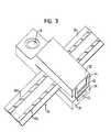
- Fig. 3 shows a strain relief device according to a second preferred Embodiment with a first holding element 30 and a second Holding element 32 in an open position with an inserted FPC flat conductor 34 with conductor tracks 38a and 38b.
- the strain relief device is made in one piece from a sufficiently rigid Plastic formed, the holding members 30 and 32 on one first narrow side to the side of the FPC flat conductor in an open position with each other are connected.
- the holding elements are in the FPC flat conductor facing areas as well as the holding elements 11 and 13 in the first embodiment.
- a resilient bracket 46 is provided on the end face 44, which over the Web 42 snaps when the second holding element 32 against the first holding element 34 is pressed.
- strain relief device 48 There is a through hole for fastening the strain relief device 48 provided that a fastening, for example on a body part made possible by means of screws or rivets.
Landscapes
- Coupling Device And Connection With Printed Circuit (AREA)
Applications Claiming Priority (2)
| Application Number | Priority Date | Filing Date | Title |
|---|---|---|---|
| DE10125656 | 2001-05-25 | ||
| DE10125656A DE10125656A1 (de) | 2001-05-25 | 2001-05-25 | Zugentlastungsvorrichtung |
Publications (1)
| Publication Number | Publication Date |
|---|---|
| EP1261069A1 true EP1261069A1 (fr) | 2002-11-27 |
Family
ID=7686210
Family Applications (1)
| Application Number | Title | Priority Date | Filing Date |
|---|---|---|---|
| EP02011205A Withdrawn EP1261069A1 (fr) | 2001-05-25 | 2002-05-21 | Dispositif de soulagement de contraintes de traction |
Country Status (2)
| Country | Link |
|---|---|
| EP (1) | EP1261069A1 (fr) |
| DE (1) | DE10125656A1 (fr) |
Families Citing this family (1)
| Publication number | Priority date | Publication date | Assignee | Title |
|---|---|---|---|---|
| DE102016107080A1 (de) * | 2016-04-18 | 2017-10-19 | Lisa Dräxlmaier GmbH | Elektrische leitungsanordnung für ein fahrzeug sowie halteteil, kontaktteilaufnahme und montageverfahren |
Citations (7)
| Publication number | Priority date | Publication date | Assignee | Title |
|---|---|---|---|---|
| US3617615A (en) * | 1970-01-19 | 1971-11-02 | Jerry L Balzer | Protector for electrical terminals |
| DE2161872A1 (de) * | 1971-01-11 | 1972-07-20 | Thomas & Betts Corp | Elektrischer Verbinder für flache Kabel |
| US4415216A (en) * | 1981-03-03 | 1983-11-15 | Thomas & Betts Corporation | Connector for mass-ground termination of multiconductor cable |
| GB2198597A (en) * | 1986-12-10 | 1988-06-15 | Amp Inc | An electrical connector assembly and a housing therefor |
| US4859205A (en) * | 1988-05-13 | 1989-08-22 | Amp Incorporated | Strain relief for flat cable termination |
| US5133674A (en) * | 1991-09-26 | 1992-07-28 | Minnesota Mining And Manufacturing Company | Flat ribbon cable strain relief fitting |
| JPH076801A (ja) * | 1993-06-15 | 1995-01-10 | Yazaki Corp | 圧接コネクタの電線保持機構 |
Family Cites Families (4)
| Publication number | Priority date | Publication date | Assignee | Title |
|---|---|---|---|---|
| JPH0755026Y2 (ja) * | 1988-02-16 | 1995-12-18 | 北川工業株式会社 | 固定具 |
| US4975076A (en) * | 1990-03-01 | 1990-12-04 | Molex Incorporated | Contact wiping electrical connector |
| DE20009788U1 (de) * | 2000-05-31 | 2000-09-07 | STOCKO Contact GmbH & Co. KG, 42327 Wuppertal | Steckverbinder zum Anschließen elektrischer Leitungen an eine Leipterplatte |
| DE20018134U1 (de) * | 2000-07-19 | 2001-01-04 | Taller Gmbh, 76337 Waldbronn | Haltevorrichtung für Leiterfolienbefestigung II |
-
2001
- 2001-05-25 DE DE10125656A patent/DE10125656A1/de not_active Withdrawn
-
2002
- 2002-05-21 EP EP02011205A patent/EP1261069A1/fr not_active Withdrawn
Patent Citations (7)
| Publication number | Priority date | Publication date | Assignee | Title |
|---|---|---|---|---|
| US3617615A (en) * | 1970-01-19 | 1971-11-02 | Jerry L Balzer | Protector for electrical terminals |
| DE2161872A1 (de) * | 1971-01-11 | 1972-07-20 | Thomas & Betts Corp | Elektrischer Verbinder für flache Kabel |
| US4415216A (en) * | 1981-03-03 | 1983-11-15 | Thomas & Betts Corporation | Connector for mass-ground termination of multiconductor cable |
| GB2198597A (en) * | 1986-12-10 | 1988-06-15 | Amp Inc | An electrical connector assembly and a housing therefor |
| US4859205A (en) * | 1988-05-13 | 1989-08-22 | Amp Incorporated | Strain relief for flat cable termination |
| US5133674A (en) * | 1991-09-26 | 1992-07-28 | Minnesota Mining And Manufacturing Company | Flat ribbon cable strain relief fitting |
| JPH076801A (ja) * | 1993-06-15 | 1995-01-10 | Yazaki Corp | 圧接コネクタの電線保持機構 |
Non-Patent Citations (1)
| Title |
|---|
| PATENT ABSTRACTS OF JAPAN vol. 1995, no. 04 31 May 1995 (1995-05-31) * |
Also Published As
| Publication number | Publication date |
|---|---|
| DE10125656A1 (de) | 2002-11-28 |
Similar Documents
| Publication | Publication Date | Title |
|---|---|---|
| DE2953181C2 (fr) | ||
| DE3709903C2 (de) | Elektrischer verbinder | |
| DE3127704C2 (de) | Verbinder zum Anschließen eines Vielleiter-Flachkabels | |
| DE69423360T2 (de) | Verbindungsvorrichtung zur elektrischen verbindung zwischen leiterplattenähnlichen elementen | |
| DE602005000612T2 (de) | Verbinder und Montageverfahren | |
| DE4419055A1 (de) | Chip-Schmelzsicherung | |
| DE10313866A1 (de) | Schnappkonstruktion | |
| DE2054201B2 (de) | Zur Verwendung in einem elektrischen Steckverbinder bestimmtes elektrisches Kontaktelement | |
| EP4151864B1 (fr) | Pince de bordure modulaire | |
| DE69010077T2 (de) | Zusammenbau flexibler Schaltungsverbindungen. | |
| DE3033886A1 (de) | Bindungsverschluss | |
| DE2707166A1 (de) | Elektrisches anschlusselement | |
| DE3828277C2 (de) | An einer Tragschiene anbringbare Schalteinheit mit zwei elektromagnetischen Kontakteinrichtungen | |
| EP2034562B1 (fr) | Connecteur à fiches doté d'un corps d'isolation en une pièce | |
| EP1675231A2 (fr) | Dispositif porte-câble | |
| DE3806049C2 (fr) | ||
| EP1261069A1 (fr) | Dispositif de soulagement de contraintes de traction | |
| AT403500B (de) | Beschlagteileverbindung | |
| DE3049066A1 (de) | Kabelband aus flexiblem, hartelastischem kunststoff | |
| DE4420072A1 (de) | Vorrichtung zum Anschließen elektrischer Leiter an einen Schaltapparat | |
| EP4424118A1 (fr) | Unité carte de circuit imprimé et élément de connexion de carte de circuit imprimé | |
| DE10016942C2 (de) | Verbinder zum Verbinden einer ersten flexiblen Leiterplatte mit einer zweiten Leiterplatte und Anordnung umfassend diese | |
| DE112021001450T5 (de) | Kopplungsaufbau | |
| DE10243407A1 (de) | Befestigungsvorrichtung für einen Stecker | |
| DE10023168C2 (de) | Kabel-oder Folienverbinder |
Legal Events
| Date | Code | Title | Description |
|---|---|---|---|
| PUAI | Public reference made under article 153(3) epc to a published international application that has entered the european phase |
Free format text: ORIGINAL CODE: 0009012 |
|
| AK | Designated contracting states |
Kind code of ref document: A1 Designated state(s): AT BE CH CY DE DK ES FI FR GB GR IE IT LI LU MC NL PT SE TR |
|
| AX | Request for extension of the european patent |
Free format text: AL;LT;LV;MK;RO;SI |
|
| AKX | Designation fees paid | ||
| 17P | Request for examination filed |
Effective date: 20030102 |
|
| RBV | Designated contracting states (corrected) |
Designated state(s): DE FR IT |
|
| REG | Reference to a national code |
Ref country code: DE Ref legal event code: 8566 |
|
| STAA | Information on the status of an ep patent application or granted ep patent |
Free format text: STATUS: THE APPLICATION IS DEEMED TO BE WITHDRAWN |
|
| 18D | Application deemed to be withdrawn |
Effective date: 20081202 |