EP1257489B2 - Selbstausrichtende transportvorrichtung für bögen mit verschiedenen breiten - Google Patents
Selbstausrichtende transportvorrichtung für bögen mit verschiedenen breiten Download PDFInfo
- Publication number
- EP1257489B2 EP1257489B2 EP01906899.8A EP01906899A EP1257489B2 EP 1257489 B2 EP1257489 B2 EP 1257489B2 EP 01906899 A EP01906899 A EP 01906899A EP 1257489 B2 EP1257489 B2 EP 1257489B2
- Authority
- EP
- European Patent Office
- Prior art keywords
- media
- rotors
- passageway
- rotor
- intermittent
- Prior art date
- Legal status (The legal status is an assumption and is not a legal conclusion. Google has not performed a legal analysis and makes no representation as to the accuracy of the status listed.)
- Expired - Lifetime
Links
- 230000007723 transport mechanism Effects 0.000 title claims description 7
- 238000000034 method Methods 0.000 claims description 4
- 230000000694 effects Effects 0.000 description 5
- 230000006399 behavior Effects 0.000 description 3
- 230000009471 action Effects 0.000 description 2
- 238000010586 diagram Methods 0.000 description 2
- 238000003780 insertion Methods 0.000 description 2
- 230000037431 insertion Effects 0.000 description 2
- 230000007246 mechanism Effects 0.000 description 2
- 230000004048 modification Effects 0.000 description 2
- 238000012986 modification Methods 0.000 description 2
- 230000002730 additional effect Effects 0.000 description 1
- 230000003542 behavioural effect Effects 0.000 description 1
- 230000009286 beneficial effect Effects 0.000 description 1
- 230000008901 benefit Effects 0.000 description 1
- 230000008859 change Effects 0.000 description 1
- 230000002301 combined effect Effects 0.000 description 1
- 230000005489 elastic deformation Effects 0.000 description 1
- 230000006872 improvement Effects 0.000 description 1
- 230000004044 response Effects 0.000 description 1
- 239000006163 transport media Substances 0.000 description 1
Images




Classifications
-
- B—PERFORMING OPERATIONS; TRANSPORTING
- B65—CONVEYING; PACKING; STORING; HANDLING THIN OR FILAMENTARY MATERIAL
- B65H—HANDLING THIN OR FILAMENTARY MATERIAL, e.g. SHEETS, WEBS, CABLES
- B65H5/00—Feeding articles separated from piles; Feeding articles to machines
- B65H5/06—Feeding articles separated from piles; Feeding articles to machines by rollers or balls, e.g. between rollers
- B65H5/062—Feeding articles separated from piles; Feeding articles to machines by rollers or balls, e.g. between rollers between rollers or balls
-
- B—PERFORMING OPERATIONS; TRANSPORTING
- B65—CONVEYING; PACKING; STORING; HANDLING THIN OR FILAMENTARY MATERIAL
- B65H—HANDLING THIN OR FILAMENTARY MATERIAL, e.g. SHEETS, WEBS, CABLES
- B65H27/00—Special constructions, e.g. surface features, of feed or guide rollers for webs
-
- B—PERFORMING OPERATIONS; TRANSPORTING
- B65—CONVEYING; PACKING; STORING; HANDLING THIN OR FILAMENTARY MATERIAL
- B65H—HANDLING THIN OR FILAMENTARY MATERIAL, e.g. SHEETS, WEBS, CABLES
- B65H2301/00—Handling processes for sheets or webs
- B65H2301/30—Orientation, displacement, position of the handled material
- B65H2301/33—Modifying, selecting, changing orientation
- B65H2301/331—Skewing, correcting skew, i.e. changing slightly orientation of material
-
- B—PERFORMING OPERATIONS; TRANSPORTING
- B65—CONVEYING; PACKING; STORING; HANDLING THIN OR FILAMENTARY MATERIAL
- B65H—HANDLING THIN OR FILAMENTARY MATERIAL, e.g. SHEETS, WEBS, CABLES
- B65H2404/00—Parts for transporting or guiding the handled material
- B65H2404/10—Rollers
- B65H2404/11—Details of cross-section or profile
- B65H2404/111—Details of cross-section or profile shape
- B65H2404/1116—Polygonal cross-section
-
- B—PERFORMING OPERATIONS; TRANSPORTING
- B65—CONVEYING; PACKING; STORING; HANDLING THIN OR FILAMENTARY MATERIAL
- B65H—HANDLING THIN OR FILAMENTARY MATERIAL, e.g. SHEETS, WEBS, CABLES
- B65H2404/00—Parts for transporting or guiding the handled material
- B65H2404/10—Rollers
- B65H2404/13—Details of longitudinal profile
- B65H2404/133—Limited number of active elements on common axis
-
- B—PERFORMING OPERATIONS; TRANSPORTING
- B65—CONVEYING; PACKING; STORING; HANDLING THIN OR FILAMENTARY MATERIAL
- B65H—HANDLING THIN OR FILAMENTARY MATERIAL, e.g. SHEETS, WEBS, CABLES
- B65H2404/00—Parts for transporting or guiding the handled material
- B65H2404/10—Rollers
- B65H2404/14—Roller pairs
- B65H2404/141—Roller pairs with particular shape of cross profile
- B65H2404/1412—Polygonal / cylindrical
-
- B—PERFORMING OPERATIONS; TRANSPORTING
- B65—CONVEYING; PACKING; STORING; HANDLING THIN OR FILAMENTARY MATERIAL
- B65H—HANDLING THIN OR FILAMENTARY MATERIAL, e.g. SHEETS, WEBS, CABLES
- B65H2701/00—Handled material; Storage means
- B65H2701/10—Handled articles or webs
- B65H2701/19—Specific article or web
- B65H2701/1912—Banknotes, bills and cheques or the like
Definitions
- banknote handling apparatus it is desirable to accommodate media of differing widths and differing flexibility. This allows a common apparatus to be deployed in different countries with minimal modification. Further, many countries have banknotes that vary in width between denominations or different versions of a given denomination. Equipment that can handle the widest possible range of denominations (and therefore widths) offers enhanced convenience for customers and increased revenue for operators.
- GB-A-2 317 881 discloses an apparatus for aligning banknotes which includes at least one guide member which is brought into contact with a note to align the note relative to at least two LED/photodiode arrangements.
- EP-A-0 848 357 also discloses an apparatus for aligning banknotes which includes a plurality of eccentric rollers mounted at a predetermined angle to a given reference surface. The banknote is aligned by the action of the rollers bringing the note into contact with the reference surface.
- a compact, simple (few moving parts) and low cost document handling device that accommodates a wide range of customer behaviors.
- the system could be adapted to many discrete media handling applications such as coupon, ticket, photograph, check, security document, banknote, card, token, mail, and general paper transport devices.
- an implementation of the transport mechanism 50 includes two substantially parallel plates (1) and (3) together with side walls (not shown) that constitute a passageway (12) through which the media (2) (shown in Figs. 3A to 4C ) is drawn into the mechanism.
- Two specially shaped rotors (4) and (8) are mounted respectively on rotating members (16) and (17).
- the rotors (4) and (8) have circular surfaces (5) and (7). respectively, which contact the media when it is inserted into the passageway (12) as the members (16) and (17) rotate.
- These members (16) and (17), together with additional members such as (18) and (19) are configured to rotate at such a speed that the outer surface velocity of the rotors (4) and (8) and discs (10) and (11) are approximately the same.
- Members (16) and (17) rotate in such a way that the phase angle between the surfaces (5) and (7) of the rotors (4) and (8) is fixed at approximately 90 degrees.
- Secondary idler members (6) (9) (13) and (15) are free to rotate when in contact with the media (2) that is being transported.
- the idler members (6) and (9) may be nip rollers.
- the spherical members (13) also permit some freedom for the media (2) to slide laterally while being driven forwards (in the direction of arrow B) at the same time.
- the five rollers (15) provide a relatively firm clamping action to the media. No further lateral movement or rotation occurs after this point.
- clamp wheels (10) are shown on shaft member (18), more or less discs (10) could be used. Similarly, more or less clamp wheels (11) could be used on shaft member (19) than the five shown in Fig. 1 .
- Fig. 2B is a simplified block diagram illustrating an overall transport system (100).
- the transport mechanism (50) is connected to a drive apparatus (60) which is connected to a controller (20).
- the drive apparatus may include an electric motor such as a stepper motor, or other known drive device capable of turning the rotating members (16, 17. 18, 19) at a uniform speed, or at different speeds, and may further be capable of turning the rotating members such that they are rotating in or out of phase with each other.
- the drive apparatus may also be capable of functioning to provide an intermittent drive to turn one or more of the rotating members.
- the controller (70) may include a microprocessor or other control circuitry for controlling the operation of the drive apparatus and transport mechanism.
- Various gearing arrangements and/or mechanical connection means between the drive apparatus and the transport mechanism may be used to accomplish such operation, and will not be discussed in detail herein.
- a special advantage of preferred embodiments of this invention is that intermittent tugs on the banknote by the surfaces (5) of the rotor (4) provide a strong behavioral signal to the customer that he may release the banknote. However, no harm will be done if a customer is slow to release the banknote, or even if the banknote is withdrawn entirely at this stage.) If the inserted banknote has some degree of skew and offset relative to the passageway (1) of the acceptor it may eventually strike one or other sidewall. At this point under the influence of the rotor (4) drive force and the drag against the passageway (1) the media will begin to rotate about the center of rotor (4) as shown by arrow (21) in Figure 3B .
- the response is a beneficial improvement in the alignment and centering of the media in the passageway.
- a plurality of rotors may be employed. Each rotor surface could be shaped and driven such that at any point in time only one rotor surface is in contact with the media (2). However, other implementations are contemplated that may utilize two or more rotor surfaces (fully or partially) to be in contact with the media surface at the same time.
- a simple variation could include the case of a singular rotor (4), which provides a less positive forward motion in exchange for greater simplicity
- a plurality of rotors such as (4) and (8) may be mounted on a common shaft such as (16). Again, each rotor may be formed and/or phased with other rotors so that at any given moment the media (2) is in contact with the surface of approximately one rotor, or fully in contact with the surface of at least one rotor and partially in contact with the surface of at least one other rotor.
- the profile of the rotors (4).(8) may take a variety of different forms and achieve similar results.
- the geometry illustrated with two circular arc contacts provides constant transport speed. However, other arrangements such as those having an ellipsoid surface, or having an uneven or intermittent surface, may be satisfactory in some circumstances.
- rotors may be convenient to use rotors with only one or more than two, driving segments.
- the rotors could be of semicircular cross section and 180 degrees out of phase or cruciform in shape with a 45-degree phase angle. Other variations are also possible.
- the intermittent drive applied to the media may also be achieved by using approximately circular rotors (4),(8) and providing a means to vary their position or clamping pressure and/or contact pressure.
- the foregoing apparatus may be combined with some known methods that align the media as required.
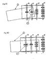
- Figures 5A and 5B show an alternate implementation 30 of the basic mechanism that is of use if bi-directional transport of the media (2) is required. Such operation may be required, for example, if it is occasionally necessary to reject a damaged or counterfeit banknote from a banknote acceptor via the same passageway that is used for insertion.
- the rotors (4).(8) are split into two parallel rotors of similar profile.
- a drive arrangement (not shown) causes the two halves of the rotors to be aligned as shown in Figure 5A during banknote insertion where they effectively act as one part to transport media in the direction of arrow B of Figures 1 and 2 .
- both surfaces (5) and (7) are used to drive the media.
- half of the rotor rotates 90 degrees with respect to its neighbor as shown in Figure 5B .
- the effect is to simulate a one-piece circular rotor having a continuous surface formed by the surfaces (5) and (7) for contact with the media.
- Such a rotor in tandem with its peers provides a direct transport along the passageway (12) in a reverse direction (opposite arrow B of Figures 1 and 2 ).
- the media (2) is restrained from rotation in this circumstance and possibly causing a jam.
- Many possible variants of rotor geometry may be combined with this implementation to achieve the same end effect.
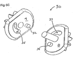
- Figure 5C is an exploded view of the combination rotor (30) of Figures 5A and 5B .
- the rotor (4) includes a guide (32) that moves in a circular slot (33) when the combination rotor is to drive media in an opposite direction.
- the rotor (8) includes a guide (34) for movement in circular slot (35) when the combination rotor (30) changes configurations as shown in Figures 5A and 5B .
Landscapes
- Engineering & Computer Science (AREA)
- Mechanical Engineering (AREA)
- Delivering By Means Of Belts And Rollers (AREA)
- Registering Or Overturning Sheets (AREA)
- Registering, Tensioning, Guiding Webs, And Rollers Therefor (AREA)
- Pile Receivers (AREA)
Claims (2)
- Vorrichtung, umfassend:einen Transportmechanismus mit zwei im Wesentlichen parallelen Platten (1, 3) mit Seitenwänden, die einen Durchgang (12) bilden, durch den ein Medium (2) eingezogen wird; undzwei Rotoren (4, 8) mit kreisbogenförmigen Flächen (5, 7), die geformt sind, ein Medium (2) auf eine intermittierende Weise anzutreiben,wobei die Rotoren (4, 8) jeweils an rotierenden Elementen (16, 17) angebracht sind, die senkrecht zu den Seitenwänden und in einer Antriebsrichtung (B) des Mediums beabstandet angeordnet sind, wobei die Elemente (16, 17) ausgestaltet sind, derart zu rotieren, dass der Phasenwinkel zwischen den kreisbogenförmigen Flächen (5, 7) der Rotoren (4, 8) bei 90 Grad festgelegt ist, sodass der intermittierende Antrieb durch intermittierenden Kontakt der Flächen mit dem Medium erzielt wird,wobei die Rotoren (4, 5) zusammen mit den Seitenwänden einen selbstausfluchtenden Transportmechanismus (50) bilden,wobei, wenn ein eingebrachtes Medium einen gewissen Grad von Schrägstellung und Versatz in Relation zu dem Durchgang (12) aufweist, intermittierendes Antreiben des Mediums durch die Rotoren (4, 5) und Ziehen des Mediums gegen den Durchgang dem eingebrachten Medium (2) erlauben, sich sowohl lateral als auch winklig selbst zu dem Durchgang (12) auszufluchten.
- Verfahren zum Ausfluchten eines Mediums beim Antreiben des Mediums entlang eines Durchgangs (12) mit Seitenwänden, wobei das Verfahren umfasstintermittierendes Antreiben des Mediums als Ergebnis eines intermittierenden Kontakts zwischen dem Medium und der Flächen (5, 7) von zwei Rotoren (4, 8), wobei die Rotoren (4, 8) jeweils an rotierenden Elementen (16, 17) angebracht sind, die senkrecht zu den Seitenwänden und in einer Antriebsrichtung (B) des Mediums beabstandet angeordnet sind, wobei sich die Elemente (16, 17) derart drehen, dass der Phasenwinkel zwischen den Flächen (5, 7) der Rotoren (4, 8) bei 90 Grad festgelegt ist,wobei, wenn ein eingebrachtes Medium einen gewissen Grad von Schrägstellung und Versatz in Relation zu dem Durchgang aufweist, intermittierendes Antreiben des Mediums durch die zwei Rotoren (4, 8) und Ziehen des Mediums gegen den Durchgang (12) dem eingebrachten Medium (2) ermöglichen, sich sowohl lateral als auch winklig selbst zu dem Durchgang (12) auszufluchten.
Applications Claiming Priority (5)
| Application Number | Priority Date | Filing Date | Title |
|---|---|---|---|
| US18130700P | 2000-02-09 | 2000-02-09 | |
| US181307P | 2000-02-09 | ||
| US769173 | 2001-01-25 | ||
| US09/769,173 US6712356B2 (en) | 2000-02-09 | 2001-01-25 | Self aligning transport mechanism for media of variable media widths |
| PCT/US2001/003384 WO2001058790A1 (en) | 2000-02-09 | 2001-02-02 | Self aligning transport mechanism for media of variable media widths |
Publications (3)
| Publication Number | Publication Date |
|---|---|
| EP1257489A1 EP1257489A1 (de) | 2002-11-20 |
| EP1257489B1 EP1257489B1 (de) | 2011-11-02 |
| EP1257489B2 true EP1257489B2 (de) | 2019-02-27 |
Family
ID=26877062
Family Applications (1)
| Application Number | Title | Priority Date | Filing Date |
|---|---|---|---|
| EP01906899.8A Expired - Lifetime EP1257489B2 (de) | 2000-02-09 | 2001-02-02 | Selbstausrichtende transportvorrichtung für bögen mit verschiedenen breiten |
Country Status (8)
| Country | Link |
|---|---|
| US (1) | US6712356B2 (de) |
| EP (1) | EP1257489B2 (de) |
| JP (1) | JP5215516B2 (de) |
| CN (1) | CN1280169C (de) |
| AU (2) | AU2001234752B2 (de) |
| CA (1) | CA2402783C (de) |
| ES (1) | ES2373940T3 (de) |
| WO (1) | WO2001058790A1 (de) |
Families Citing this family (12)
| Publication number | Priority date | Publication date | Assignee | Title |
|---|---|---|---|---|
| JP4456749B2 (ja) * | 2000-11-02 | 2010-04-28 | 富士通株式会社 | 柔軟媒体物搬送シミュレーション装置 |
| EP1433728A1 (de) * | 2002-12-23 | 2004-06-30 | Mars Incorporated | Fördervorrichtung für Banknoten |
| JP4366096B2 (ja) * | 2003-02-24 | 2009-11-18 | キヤノン株式会社 | 情報処理装置及びそのシミュレーション方法並びに記憶媒体 |
| US6971647B2 (en) * | 2003-07-22 | 2005-12-06 | Hewlett-Packard Development Company, L.P. | Media registration mechanism for image forming device |
| JP4230874B2 (ja) * | 2003-10-01 | 2009-02-25 | 株式会社小森コーポレーション | 排紙装置及びその方法 |
| US7648138B2 (en) * | 2004-09-14 | 2010-01-19 | Hitachi-Omron Terminal Solutions, Corp. | Sheet handling apparatus |
| JP2011255976A (ja) * | 2010-06-04 | 2011-12-22 | Japan Cash Machine Co Ltd | 紙葉類搬送装置 |
| JP5614359B2 (ja) * | 2011-03-31 | 2014-10-29 | 沖電気工業株式会社 | 繰り出しローラ |
| CN102968823B (zh) * | 2012-11-01 | 2015-11-18 | 高新现代智能系统股份有限公司 | 一种票卡码齐机构及方法 |
| US10504315B2 (en) * | 2013-08-05 | 2019-12-10 | Ncr Corporation | Clamping of media items |
| EP3374300B1 (de) | 2015-11-11 | 2022-05-04 | Crane Payment Innovations, Inc. | Begradigungsmechanismus mit verdrehsicherung |
| JP6405425B1 (ja) | 2017-08-08 | 2018-10-17 | 日本金銭機械株式会社 | 摩擦搬送装置、及び紙葉搬送装置 |
Family Cites Families (24)
| Publication number | Priority date | Publication date | Assignee | Title |
|---|---|---|---|---|
| US3603446A (en) | 1969-03-27 | 1971-09-07 | Black Clawson Co | Sheet-straightening mechanism |
| GB1447888A (en) | 1973-11-21 | 1976-09-02 | Xerox Corp | Sheet feeding apparatus |
| FR2360133A1 (fr) | 1976-07-30 | 1978-02-24 | Titn | Procede et appareil de balayage d'un support avec compensation des defauts de positionnement et des variations de dimensions |
| US4438917A (en) | 1981-10-16 | 1984-03-27 | International Business Machines Corporation | Dual motor aligner |
| JPS6090232U (ja) | 1983-11-22 | 1985-06-20 | ローレルバンクマシン株式会社 | 紙幣取込装置 |
| GB8515272D0 (en) | 1985-06-17 | 1985-07-17 | De La Rue Syst | Monitoring sheet length |
| US4971304A (en) | 1986-12-10 | 1990-11-20 | Xerox Corporation | Apparatus and method for combined deskewing and side registering |
| US4918463A (en) | 1987-03-02 | 1990-04-17 | Eastman Kodak Company | Compact printer having an integral cut-sheet feeder |
| US4833591A (en) | 1987-12-30 | 1989-05-23 | Pitney Bowes Inc. | Method for aligning a moving substrate and a read or write head |
| US4855607A (en) | 1987-12-30 | 1989-08-08 | Pitney Bowes, Inc. | Apparatus for aligning a moving substrate and a read or write head |
| JPH0745495Y2 (ja) | 1988-02-24 | 1995-10-18 | 旭光学工業株式会社 | 連続記録紙を用いるプリンタの搬送異常検知機構 |
| JPH0210338U (de) * | 1988-07-05 | 1990-01-23 | ||
| JP2724860B2 (ja) * | 1989-01-11 | 1998-03-09 | 株式会社日立製作所 | 紙葉類の方向変換装置 |
| JP2566651B2 (ja) * | 1989-05-10 | 1996-12-25 | キヤノン株式会社 | 画像形成装置 |
| JPH03172269A (ja) * | 1989-11-30 | 1991-07-25 | Canon Inc | シート搬送装置 |
| ES2088400T3 (es) | 1989-12-07 | 1996-08-16 | Mars Inc | Dispositivo para la orientacion de hojas. |
| US5094442A (en) | 1990-07-30 | 1992-03-10 | Xerox Corporation | Translating electronic registration system |
| US5090683A (en) | 1990-07-31 | 1992-02-25 | Xerox Corporation | Electronic sheet rotator with deskew, using single variable speed roller |
| US5078384A (en) | 1990-11-05 | 1992-01-07 | Xerox Corporation | Combined differential deskewing and non-differential registration of sheet material using plural motors |
| JPH07137890A (ja) * | 1993-06-30 | 1995-05-30 | Fuji Xerox Co Ltd | 手差し給紙装置における用紙の方向変換装置 |
| JP3822652B2 (ja) | 1994-04-26 | 2006-09-20 | ブラザー工業株式会社 | 用紙搬送装置 |
| GB2317881B (en) | 1994-09-23 | 1998-06-17 | Mars Inc | Method and apparatus for aligning a bank note |
| JP3361979B2 (ja) | 1996-12-09 | 2003-01-07 | ローレルバンクマシン株式会社 | 紙幣処理機の紙幣整列装置 |
| EP1149362A1 (de) | 1999-02-02 | 2001-10-31 | Cashcode Company Inc. | Banknotenzentrierungsanordnung für einen prüfer |
-
2001
- 2001-01-25 US US09/769,173 patent/US6712356B2/en not_active Expired - Lifetime
- 2001-02-02 EP EP01906899.8A patent/EP1257489B2/de not_active Expired - Lifetime
- 2001-02-02 AU AU2001234752A patent/AU2001234752B2/en not_active Ceased
- 2001-02-02 CA CA2402783A patent/CA2402783C/en not_active Expired - Fee Related
- 2001-02-02 ES ES01906899T patent/ES2373940T3/es not_active Expired - Lifetime
- 2001-02-02 JP JP2001558352A patent/JP5215516B2/ja not_active Expired - Fee Related
- 2001-02-02 WO PCT/US2001/003384 patent/WO2001058790A1/en not_active Ceased
- 2001-02-02 AU AU3475201A patent/AU3475201A/xx active Pending
- 2001-02-02 CN CNB018046371A patent/CN1280169C/zh not_active Expired - Fee Related
Also Published As
| Publication number | Publication date |
|---|---|
| EP1257489B1 (de) | 2011-11-02 |
| ES2373940T3 (es) | 2012-02-10 |
| US6712356B2 (en) | 2004-03-30 |
| WO2001058790A9 (en) | 2002-10-31 |
| CA2402783A1 (en) | 2001-08-16 |
| US20010045697A1 (en) | 2001-11-29 |
| CA2402783C (en) | 2010-01-26 |
| AU3475201A (en) | 2001-08-20 |
| CN1280169C (zh) | 2006-10-18 |
| EP1257489A1 (de) | 2002-11-20 |
| CN1406195A (zh) | 2003-03-26 |
| JP5215516B2 (ja) | 2013-06-19 |
| JP2003522698A (ja) | 2003-07-29 |
| WO2001058790A1 (en) | 2001-08-16 |
| AU2001234752B2 (en) | 2005-08-04 |
Similar Documents
| Publication | Publication Date | Title |
|---|---|---|
| EP1257489B1 (de) | Selbstausrichtende transportvorrichtung für bögen mit verschiedenen breiten | |
| US7950518B2 (en) | Apparatus for aligning vouchers | |
| AU2001234752A1 (en) | Self aligning transport mechanism for media of variable media widths | |
| KR101681503B1 (ko) | 지폐 자동정렬장치 및 사행조정유닛 | |
| US11655116B2 (en) | Apparatus for aligning notes of value | |
| TW445216B (en) | Passbook handling device | |
| ZA200205793B (en) | Self aligning transport mechanism for media of variable Imedia widths. | |
| JP5608814B2 (ja) | 紙葉類識別装置 | |
| JP2004054809A (ja) | 紙葉類情報取得装置 | |
| CN114174204A (zh) | 用于运输有价票券的装置 | |
| JP2015099425A (ja) | 紙幣処理装置 | |
| JP2017159999A (ja) | 紙葉類取扱装置及び紙葉類取扱方法 | |
| KR102177762B1 (ko) | 금융 자동화 기기의 매체 이송장치 | |
| JP4376121B2 (ja) | 媒体搬送装置 | |
| JP3676118B2 (ja) | カード搬送機構 | |
| CN110021107B (zh) | 用于处理有面值的纸币的装置 | |
| JPH0333715Y2 (de) | ||
| JP3693277B2 (ja) | 媒体幅寄せ装置 | |
| JPH0720121Y2 (ja) | 紙葉類搬送装置 | |
| JPH1025040A (ja) | 媒体幅寄せ制御システム | |
| KR20210080015A (ko) | 금융자동화기기 및 금융자동화기기의 매체 반송경로 절환장치 | |
| JP2000163519A (ja) | 記録媒体の搬送装置 | |
| JPS5919988Y2 (ja) | カ−ドリ−ダ−のリジエクト装置 | |
| JPS63194968A (ja) | 印字装置 | |
| JP2003162747A (ja) | 紙葉類情報取得装置 |
Legal Events
| Date | Code | Title | Description |
|---|---|---|---|
| PUAI | Public reference made under article 153(3) epc to a published international application that has entered the european phase |
Free format text: ORIGINAL CODE: 0009012 |
|
| 17P | Request for examination filed |
Effective date: 20020903 |
|
| AK | Designated contracting states |
Kind code of ref document: A1 Designated state(s): AT BE CH CY DE DK ES FI FR GB GR IE IT LI LU MC NL PT SE TR |
|
| AX | Request for extension of the european patent |
Free format text: AL;LT;LV;MK;RO;SI |
|
| 17Q | First examination report despatched |
Effective date: 20030331 |
|
| RBV | Designated contracting states (corrected) |
Designated state(s): DE ES FR GB IT |
|
| RAP1 | Party data changed (applicant data changed or rights of an application transferred) |
Owner name: MEI, INC. |
|
| 17Q | First examination report despatched |
Effective date: 20030331 |
|
| 111Z | Information provided on other rights and legal means of execution |
Free format text: DEESFRGBIT Effective date: 20061103 |
|
| 111Z | Information provided on other rights and legal means of execution |
Free format text: DE ES FR GB IT Effective date: 20070802 |
|
| GRAP | Despatch of communication of intention to grant a patent |
Free format text: ORIGINAL CODE: EPIDOSNIGR1 |
|
| GRAS | Grant fee paid |
Free format text: ORIGINAL CODE: EPIDOSNIGR3 |
|
| GRAA | (expected) grant |
Free format text: ORIGINAL CODE: 0009210 |
|
| AK | Designated contracting states |
Kind code of ref document: B1 Designated state(s): DE ES FR GB IT |
|
| REG | Reference to a national code |
Ref country code: GB Ref legal event code: FG4D |
|
| REG | Reference to a national code |
Ref country code: DE Ref legal event code: R096 Ref document number: 60145599 Country of ref document: DE Effective date: 20120112 |
|
| REG | Reference to a national code |
Ref country code: ES Ref legal event code: FG2A Ref document number: 2373940 Country of ref document: ES Kind code of ref document: T3 Effective date: 20120210 |
|
| PLBI | Opposition filed |
Free format text: ORIGINAL CODE: 0009260 |
|
| PLAX | Notice of opposition and request to file observation + time limit sent |
Free format text: ORIGINAL CODE: EPIDOSNOBS2 |
|
| 26 | Opposition filed |
Opponent name: EDER, CHRISTIAN Effective date: 20120801 |
|
| REG | Reference to a national code |
Ref country code: DE Ref legal event code: R026 Ref document number: 60145599 Country of ref document: DE Effective date: 20120801 |
|
| PLBB | Reply of patent proprietor to notice(s) of opposition received |
Free format text: ORIGINAL CODE: EPIDOSNOBS3 |
|
| PLAB | Opposition data, opponent's data or that of the opponent's representative modified |
Free format text: ORIGINAL CODE: 0009299OPPO |
|
| R26 | Opposition filed (corrected) |
Opponent name: EDER, CHRISTIAN Effective date: 20120801 |
|
| RDAF | Communication despatched that patent is revoked |
Free format text: ORIGINAL CODE: EPIDOSNREV1 |
|
| PGFP | Annual fee paid to national office [announced via postgrant information from national office to epo] |
Ref country code: FR Payment date: 20140211 Year of fee payment: 14 |
|
| APBM | Appeal reference recorded |
Free format text: ORIGINAL CODE: EPIDOSNREFNO |
|
| APBP | Date of receipt of notice of appeal recorded |
Free format text: ORIGINAL CODE: EPIDOSNNOA2O |
|
| APAH | Appeal reference modified |
Free format text: ORIGINAL CODE: EPIDOSCREFNO |
|
| RAP2 | Party data changed (patent owner data changed or rights of a patent transferred) |
Owner name: MEI, INC. |
|
| APBQ | Date of receipt of statement of grounds of appeal recorded |
Free format text: ORIGINAL CODE: EPIDOSNNOA3O |
|
| PGFP | Annual fee paid to national office [announced via postgrant information from national office to epo] |
Ref country code: IT Payment date: 20150216 Year of fee payment: 15 Ref country code: ES Payment date: 20150113 Year of fee payment: 15 |
|
| REG | Reference to a national code |
Ref country code: FR Ref legal event code: ST Effective date: 20151030 |
|
| REG | Reference to a national code |
Ref country code: DE Ref legal event code: R082 Ref document number: 60145599 Country of ref document: DE Representative=s name: PETERREINS SCHLEY PATENT- UND RECHTSANWAELTE P, DE Ref country code: DE Ref legal event code: R082 Ref document number: 60145599 Country of ref document: DE Representative=s name: PETERREINS SCHLEY PATENT- UND RECHTSANWAELTE, DE |
|
| PG25 | Lapsed in a contracting state [announced via postgrant information from national office to epo] |
Ref country code: FR Free format text: LAPSE BECAUSE OF NON-PAYMENT OF DUE FEES Effective date: 20150302 |
|
| PG25 | Lapsed in a contracting state [announced via postgrant information from national office to epo] |
Ref country code: IT Free format text: LAPSE BECAUSE OF NON-PAYMENT OF DUE FEES Effective date: 20160202 |
|
| PG25 | Lapsed in a contracting state [announced via postgrant information from national office to epo] |
Ref country code: ES Free format text: LAPSE BECAUSE OF NON-PAYMENT OF DUE FEES Effective date: 20160203 |
|
| PLAB | Opposition data, opponent's data or that of the opponent's representative modified |
Free format text: ORIGINAL CODE: 0009299OPPO |
|
| R26 | Opposition filed (corrected) |
Opponent name: EDER, CHRISTIAN Effective date: 20120801 |
|
| APBU | Appeal procedure closed |
Free format text: ORIGINAL CODE: EPIDOSNNOA9O |
|
| PGFP | Annual fee paid to national office [announced via postgrant information from national office to epo] |
Ref country code: GB Payment date: 20180131 Year of fee payment: 18 |
|
| PUAH | Patent maintained in amended form |
Free format text: ORIGINAL CODE: 0009272 |
|
| STAA | Information on the status of an ep patent application or granted ep patent |
Free format text: STATUS: PATENT MAINTAINED AS AMENDED |
|
| RAP2 | Party data changed (patent owner data changed or rights of a patent transferred) |
Owner name: CRANE PAYMENT INNOVATIONS, INC. |
|
| 27A | Patent maintained in amended form |
Effective date: 20190227 |
|
| AK | Designated contracting states |
Kind code of ref document: B2 Designated state(s): DE ES FR GB IT |
|
| REG | Reference to a national code |
Ref country code: DE Ref legal event code: R102 Ref document number: 60145599 Country of ref document: DE |
|
| PGFP | Annual fee paid to national office [announced via postgrant information from national office to epo] |
Ref country code: DE Payment date: 20190122 Year of fee payment: 19 |
|
| GBPC | Gb: european patent ceased through non-payment of renewal fee |
Effective date: 20190202 |
|
| PG25 | Lapsed in a contracting state [announced via postgrant information from national office to epo] |
Ref country code: GB Free format text: LAPSE BECAUSE OF NON-PAYMENT OF DUE FEES Effective date: 20190202 |
|
| REG | Reference to a national code |
Ref country code: DE Ref legal event code: R119 Ref document number: 60145599 Country of ref document: DE |
|
| PG25 | Lapsed in a contracting state [announced via postgrant information from national office to epo] |
Ref country code: DE Free format text: LAPSE BECAUSE OF NON-PAYMENT OF DUE FEES Effective date: 20200901 |