EP1250525B1 - Procede et dispositif pour commander un moteur a combustion interne - Google Patents
Procede et dispositif pour commander un moteur a combustion interne Download PDFInfo
- Publication number
- EP1250525B1 EP1250525B1 EP00983352A EP00983352A EP1250525B1 EP 1250525 B1 EP1250525 B1 EP 1250525B1 EP 00983352 A EP00983352 A EP 00983352A EP 00983352 A EP00983352 A EP 00983352A EP 1250525 B1 EP1250525 B1 EP 1250525B1
- Authority
- EP
- European Patent Office
- Prior art keywords
- fuel quantity
- fuel
- internal combustion
- combustion engine
- metered
- Prior art date
- Legal status (The legal status is an assumption and is not a legal conclusion. Google has not performed a legal analysis and makes no representation as to the accuracy of the status listed.)
- Expired - Lifetime
Links
Images
Classifications
-
- F—MECHANICAL ENGINEERING; LIGHTING; HEATING; WEAPONS; BLASTING
- F02—COMBUSTION ENGINES; HOT-GAS OR COMBUSTION-PRODUCT ENGINE PLANTS
- F02D—CONTROLLING COMBUSTION ENGINES
- F02D41/00—Electrical control of supply of combustible mixture or its constituents
- F02D41/30—Controlling fuel injection
- F02D41/38—Controlling fuel injection of the high pressure type
- F02D41/40—Controlling fuel injection of the high pressure type with means for controlling injection timing or duration
- F02D41/402—Multiple injections
- F02D41/405—Multiple injections with post injections
-
- F—MECHANICAL ENGINEERING; LIGHTING; HEATING; WEAPONS; BLASTING
- F02—COMBUSTION ENGINES; HOT-GAS OR COMBUSTION-PRODUCT ENGINE PLANTS
- F02D—CONTROLLING COMBUSTION ENGINES
- F02D41/00—Electrical control of supply of combustible mixture or its constituents
- F02D41/02—Circuit arrangements for generating control signals
- F02D41/14—Introducing closed-loop corrections
- F02D41/1497—With detection of the mechanical response of the engine
-
- F—MECHANICAL ENGINEERING; LIGHTING; HEATING; WEAPONS; BLASTING
- F02—COMBUSTION ENGINES; HOT-GAS OR COMBUSTION-PRODUCT ENGINE PLANTS
- F02D—CONTROLLING COMBUSTION ENGINES
- F02D2250/00—Engine control related to specific problems or objectives
- F02D2250/18—Control of the engine output torque
-
- F—MECHANICAL ENGINEERING; LIGHTING; HEATING; WEAPONS; BLASTING
- F02—COMBUSTION ENGINES; HOT-GAS OR COMBUSTION-PRODUCT ENGINE PLANTS
- F02D—CONTROLLING COMBUSTION ENGINES
- F02D2250/00—Engine control related to specific problems or objectives
- F02D2250/38—Control for minimising smoke emissions, e.g. by applying smoke limitations on the fuel injection amount
-
- Y—GENERAL TAGGING OF NEW TECHNOLOGICAL DEVELOPMENTS; GENERAL TAGGING OF CROSS-SECTIONAL TECHNOLOGIES SPANNING OVER SEVERAL SECTIONS OF THE IPC; TECHNICAL SUBJECTS COVERED BY FORMER USPC CROSS-REFERENCE ART COLLECTIONS [XRACs] AND DIGESTS
- Y02—TECHNOLOGIES OR APPLICATIONS FOR MITIGATION OR ADAPTATION AGAINST CLIMATE CHANGE
- Y02T—CLIMATE CHANGE MITIGATION TECHNOLOGIES RELATED TO TRANSPORTATION
- Y02T10/00—Road transport of goods or passengers
- Y02T10/10—Internal combustion engine [ICE] based vehicles
- Y02T10/40—Engine management systems
Definitions
- the invention relates to a method and a device for controlling a Internal combustion engine, in particular a gasoline engine with direct fuel injection, according to the preambles of the independent claims.
- Modern engines are e.g. with a view to reducing the Fuel consumption and the emitted pollutants and in terms of a trouble-free operation ever higher demands made.
- the requirements should be in all load conditions of the internal combustion engine and also when changing be met between different load conditions.
- the different Loading conditions essentially result from the current driving situation Consideration of the driver of the internal combustion engine having Vehicle expressed driver's request for reduction or increase of the Internal combustion engine provided torque.
- the torque setpoint is, in vehicles with gasoline engine, in a Target position for the throttle implemented, resulting in vehicles with electronic Motor power control (EGas) electronically via electromotive Throttle valve adjustment takes place.
- EMGas Electronic Motor power control
- Throttle valve adjustment takes place.
- Ignition angle or injection angle for generating the desired torque required amount of fuel to be metered to the engine, e.g. by Calculation determined.
- the desired torque generates corresponding torque.
- the fuel metering is preferably carried out by fuel injection, in particular by direct injection into one Combustion chamber of the internal combustion engine.
- the air sucked in by the internal combustion engine is used or an air mass or air mass signal representing this intake air as Reference variable for determining the quantity of fuel to be metered.
- One Air flow meter gives information about the intake air volume to the controller.
- Other sensors or sensors determine all other, for fuel allocation necessary data and report this to the controller, in particular data on the Engine speed and the load state of the internal combustion engine. From these Input variables are the optimal parameters, in particular for the injected Fuel quantity or the injection time, if necessary, the set firing angle and / or the determined to be metered air filling.
- the assignment of the control variables to the Input variables are carried out in modern controllers via corresponding maps of the Control.
- Air ratio ⁇ characterizes that the ratio between the supplied air quantity and indicates the theoretical air requirement for perfect combustion.
- ⁇ 1 an ideal value (homogeneous mixture)
- values ⁇ ⁇ 1 correspond to a lack of air or a rich mixture and are used e.g. set at engine start and at full load
- values ⁇ > 1 correspond to an excess of air or a lean mixture, as it is e.g. in the partial load range to achieve a particularly economical operation is sought.
- the invention is based on the object, the disadvantages of the prior art avoid.
- the invention proposes a method with the features of Claim 1 and an apparatus having the features of claim 7 before.
- preferred Further developments are specified in the dependent claims. The wording of all Claims are incorporated herein by reference.
- this Efficiency not only of the metered amount of fuel, but in particular also from the time of fuel metering during a working stroke and depends on the actual mixture composition.
- the efficiency changes depending on the operating point.
- defining factors can also Normal values or optimum values are assumed.
- the assignment between Input variable (desired torque) and output variable (normal fuel quantity or corresponding signal) of this determination can in a basic map for the Reference mode can be performed.
- determining the current or relative efficiency ⁇ in particular the actual values of injection or ignition angle detected by corresponding sensors, of exhaust gas recirculation and / or by throttling and / or charging adjusted, sucked fresh air mass are taken into account.
- the relative Efficiency will often differ from normal efficiency, but it can also be this same if the current operating state that operating state corresponds, which serves as a basis for calculating the normal efficiency.
- a correction of the Value for the normal fuel quantity to the actual metered Determine fuel quantity.
- the actual amount of fuel to be metered will be in the rule of the amount of normal fuel present as an arithmetic variable differ. However, it can also be equal to the normal fuel amount, if the relative efficiency to the underlying, accepting normal efficiency equivalent.
- the modeling according to the invention of the relative efficiency ⁇ and its Consideration in the fuel metering has the consequence in particular that Switching between different modes of torque continuity is maintained and torque jumps are prevented.
- the invention allows So a continuous or stepless, essentially jerk-free representation or Provision of the desired torque even with firing process side Conditional switching of the operating mode (air-fuel ratio, injection or Ignition angle) of the internal combustion engine.
- At the same time or substantially simultaneously with the determination of the actually metered Amount of fuel can be a control of the setpoints for injection or ignition angle, Exhaust gas recirculation and / or by throttling and / or charging to be adjusted sucked fresh air mass and possibly other sizes depending from the desired operating mode of the internal combustion engine according to predetermined Maps done.
- the air mass can remain relatively static.
- control measures for adjusting the driving behavior to the Driving dynamics may be provided, for example, a jerk damping and / or a To carry out load shock absorption.
- a control position desired torque before determining the Amount of fuel to be metered based on adjustment parameters Driving behavior is corrected, whereby the input variable for the described efficiency-optimized fuel quantity calculation can be changed can.
- Traction control a Traction control
- MSR motor drag torque control
- Traction systems can be effected in a suitable manner before the consideration of the fuel quantity to be metered become.
- intervention of a traction control the one Torque corresponding input for the efficiency-optimized Fuel level measurement corrected to differ from the expressed Driver's request to generate the torque in such a way that slip is taken into account.
- a for a maximum of smoke-free combustion maximum allowable admissible Maximum fuel quantity is determined and that a limit of the actual amount of fuel to be metered is performed on this maximum amount of fuel.
- This measure suitable for smoke limitation can have dynamic effects take into account, for example, arise in that in a driving situation short-term insufficient air for the generation of the desired torque required combustion is available. This can pollutant emissions the engine are minimized even in extreme situations.
- the actual amount of fuel injected may be smaller than the determined on the basis of the efficiency model, corresponding to the driver's request Fuel quantity.
- the invention in particular allows the described disadvantages in operation avoid gasoline engines with direct injection.
- the invention can also be applied to other types of fuel metering, especially in port injection, with Advantage be used.
- inventive method in which the efficiency of injections as Boundary specification is possible.
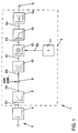
- Fig. 1 is a section of an electronic control unit 1 for Control of a trained as a gasoline engine with direct fuel injection Internal combustion engine shown.
- the control unit has a not shown Input circuit, at least one microcomputer for processing digital signals and an output circuit (not shown), these elements being connected via a suitable output circuit Communication link connected to each other for mutual data exchange are.
- To the input circuit are not shown, leading to measuring devices Input lines to various measuring devices connected to the Control unit all parameters required for an optimal combustion process in Form suitable signals for evaluation.
- To the input circuit are in particular a measuring device for detecting the engine speed, a Measuring device for detecting the fresh air supplied to the internal combustion engine and a measuring device for detecting the position of the throttle valve Internal combustion engine connected.
- the input circuit can receive signals for further operating variables of the Internal combustion engine and / or the vehicle to be supplied, which is used to control the Internal combustion engine to be evaluated.
- Such operating variables are, for example Intake air temperature, ambient pressure, intake manifold pressure, exhaust gas composition or Like.
- a schematically illustrated connected measuring device 2 for detecting the Position of the accelerator pedal is used to supply the control unit with a signal that the Driver request, so the desire of the driver to reduce or increase the represents instantaneous torque of the internal combustion engine.
- the control unit outputs signals for controlling the Performance of the internal combustion engine.
- the amount of fuel metering represented by an intake time Zündzeittician or ignition angle and, via a setting of a throttle valve Internal combustion engine, which controls the filling of the internal combustion engine.
- Fuel quantity determination device 3 is used, which integrates into the control unit 1 is.
- the operation of the Kraftstoffmengenemnittlungs worn is for the sake of Clarity presented in the form of a flow chart.
- the realization of the Control method according to the invention takes place in the preferred embodiment as Program of a microcomputer of the control unit.
- the elements shown in Fig. 1 therefore represent programs, program parts or program steps such Realization as well as the corresponding paths of the signal line.
- a target value for a torque of the internal combustion engine is given.
- a desired torque or Torque setpoint corresponding signal is in the illustrated embodiment provided first characteristic field 4, which is also referred to as driving characteristics map and that from the signal for accelerator pedal position and the signal for the engine speed the Determining the desired torque or desired torque corresponding to these values and emits a corresponding signal D1
- a Juckeldämpfung Provided on the vehicle facilities for dynamic driving behavior control are present, for example, a Juckeldämpfung, a transmission control and / or Other measures in the powertrain, their influences on the Desired torque in a second map 5 from corresponding measured values or Control variables determined and to generate a relation to the signal D1 if necessary modified signal D2 be modified at the output of the second map 5.
- Desired torque signal D2 due to these interventions at a suitable point 6 of Signal processing are modified to a desired torque signal D3, the taken into account external torque intervention.
- the signal D3 corresponding to the optionally modified desired torque serves as a Input signal of a first device 10 of the fuel quantity determination device 3.
- the first device 10 determines from the torque requirement representing Input signal D3 based on an assumed and by corresponding Programming given normal efficiency of a fuel metering a value for a normal fuel quantity, assuming the normal efficiency a desired torque entered would generate torque.
- a representing this normal fuel quantity first signal K1 is output.
- the basis of calculation can also be modes with ⁇ ⁇ 1 or ⁇ > 1 are used.
- a second device 11 based on at least one of the current operating conditions of the internal combustion engine representing operating signal as a reference for the fuel quantity determination calculated a so-called "relative efficiency" ⁇ and a relative Efficiency ⁇ representative second signal K2 outputs.
- the relative efficiency is doing in a suitable efficiency model in the control unit existing measurement and control variables determined.
- the by Throttling and / or charging set intake fresh air mass correspond and are determined by the current throttle position.
- the current relative efficiency is appropriate constantly, for example at a distance of every few milliseconds, determined.
- a detected air mass signal (or Air quantity signal) in the control of the internal combustion engine as a reference variable for the Calculation of the amount of fuel, the ignition timing, etc. is at Process according to the invention such that the efficiency of a Injection at given operating conditions as limit specification and leading variable used and used to determine the actual metered amount of fuel becomes.
- a device 13 for smoke limitation with a provided corresponding map determines based on the over one suitable measuring device detected, actually available for combustion a maximum amount of air for a substantially smoke-free combustion permissible maximum quantity of fuel to be metered. This will be accompanied by the signal K3, based on efficiency calculations, efficiency-optimized fuel quantity compared. In cases where the efficiency-optimized metered amount of fuel (signal K3) is greater than that Maximum amount of fuel, is the maximum amount of fuel corresponding signal S4 read out or issued, otherwise it remains at the signal S3. Thereby can dynamic effects, such as those caused by short-term lack of air can be taken into account.
- the output signal representing a certain amount of fuel to be injected The fuel quantity determination device finally serves as an input signal of a another map 14, depending on the desired amount of fuel the this corresponding injection time Ti calculated.
Landscapes
- Engineering & Computer Science (AREA)
- Chemical & Material Sciences (AREA)
- Combustion & Propulsion (AREA)
- Mechanical Engineering (AREA)
- General Engineering & Computer Science (AREA)
- Electrical Control Of Air Or Fuel Supplied To Internal-Combustion Engine (AREA)
- Combined Controls Of Internal Combustion Engines (AREA)
- Control Of Vehicle Engines Or Engines For Specific Uses (AREA)
Abstract
Claims (7)
- Procédé pour commander un moteur à combustion interne, notamment un moteur à allumage par étincelle avec injection directe de carburant, comprenant les étapes suivantes :caractérisé en ce que la détection de la quantité de carburant à distribuer comprend les étapes suivantes :détection d'un couple souhaité sur là base de la position d'au moins un élément de commande actionné par un conducteur ;détection d'une quantité de carburant nécessaire pour produire le couple souhaité, à distribuer au moteur à combustion interne ;production d'un couple du moteur à combustion interne correspondant au couple souhaité par distribution de la quantité de carburant détectée au moteur à combustion interne,détection d'une quantité de carburant normale sur la base d'un rendement normal prédéfini ;détection d'un rendement relatif sur la base des conditions de fonctionnement actuelles du moteur à combustion interne ;correction de la quantité de carburant normale par rapport au rendement relatif pour détecter la quantité de carburant à distribuer effectivement.
- Procédé selon la revendication 1, caractérisé en ce que pendant un temps de travail du moteur à combustion interne, on effectue en plus d'une distribution principale de carburant, au moins une distribution secondaire de carburant, en ce que la détection du rendement relatif pour chacune des distributions est effectuée séparément et en ce que la quantité de carburant secondaire à distribuer, correspondant à l'au moins une distribution secondaire, est prise en compte lors de la détection de la quantité de carburant à distribuer effectivement, à partir de la quantité de carburant principale détectée, notamment par soustraction de la quantité de carburant secondaire de la quantité de carburant principale.
- Procédé selon la revendication 1 ou 2, caractérisé en ce qu'avant une détection de la quantité de carburant à distribuer, basée sur le rendement, le couple souhaité est corrigé sur la base de paramètres destinés à influencer le comportement de conduite.
- Procédé selon l'une quelconque des revendications précédentes, caractérisé en ce qu'avant une détection de la quantité de carburant à distribuer, basée sur le rendement, le couple souhaité est corrigé sur la base d'au moins un paramètre d'intervention externe sur le couple, un paramètre d'intervention sur le couple étant en particulier fourni par une régulation du glissement d'entraínement et/ou par une régulation du couple d'entraínement du moteur.
- Procédé selon l'une quelconque des revendications précédentes, caractérisé en ce que sur la base de la quantité d'air disponible pour la combustion, on détecte une quantité de carburant maximale admissible à distribuer pour une combustion essentiellement sans fumée, et en ce que l'on effectue une limitation de la quantité de carburant à distribuer effectivement à la quantité de carburant maximale.
- Procédé selon l'une quelconque des revendications précédentes, caractérisé en ce que la distribution de la quantité de carburant à distribuer effectivement s'effectue par injection directe de la quantité de carburant dans une chambre de combustion du moteur à combustion interne, et/ou en ce que le moteur à combustion interne est un moteur à allumage par étincelle.
- Dispositif de commande d'un moteur à combustion interne, notamment d'un moteur à allumage par étincelle avec injection directe de carburant, comprenant une unité de commande électronique qui présente au moins un dispositif de détection de la quantité de carburant pour détecter une quantité de carburant nécessaire pour produire un couple souhaité, à distribuer effectivement au moteur à combustion interne, le couple souhaité étant détecté au moins sur la base de la position d'au moins un élément de commande actionnable par un conducteur, caractérisé en ce que le dispositif de détection de la quantité de carburant (3) présente un premier dispositif (10) pour détecter une quantité de carburant normale sur la base d'un rendement normal prédéfini et pour délivrer au moins un premier signal (K1) représentant la quantité de carburant normale ; un deuxième dispositif (11) pour détecter un rendement relatif sur la base d'au moins un signal de fonctionnement représentant les conditions de fonctionnement actuelles du moteur à combustion interne et pour délivrer un deuxième signal (K2) représentant le rendement relatif ; et un dispositif de correction (12) pour corriger le premier signal (K1) sur la base du deuxième signal (K2) et pour produire un signal de quantité de carburant (K3) représentant la quantité de carburant à distribuer effectivement.
Applications Claiming Priority (3)
| Application Number | Priority Date | Filing Date | Title |
|---|---|---|---|
| DE10000918 | 2000-01-12 | ||
| DE10000918A DE10000918A1 (de) | 2000-01-12 | 2000-01-12 | Verfahren und Vorrichtung zur Steuerung einer Brennkraftmaschine |
| PCT/EP2000/013007 WO2001051794A1 (fr) | 2000-01-12 | 2000-12-20 | Procede et dispositif pour commander un moteur a combustion interne |
Publications (2)
| Publication Number | Publication Date |
|---|---|
| EP1250525A1 EP1250525A1 (fr) | 2002-10-23 |
| EP1250525B1 true EP1250525B1 (fr) | 2005-07-06 |
Family
ID=7627246
Family Applications (1)
| Application Number | Title | Priority Date | Filing Date |
|---|---|---|---|
| EP00983352A Expired - Lifetime EP1250525B1 (fr) | 2000-01-12 | 2000-12-20 | Procede et dispositif pour commander un moteur a combustion interne |
Country Status (7)
| Country | Link |
|---|---|
| US (1) | US6578546B2 (fr) |
| EP (1) | EP1250525B1 (fr) |
| JP (1) | JP2003519751A (fr) |
| CN (1) | CN1243909C (fr) |
| AU (1) | AU2001220120A1 (fr) |
| DE (2) | DE10000918A1 (fr) |
| WO (1) | WO2001051794A1 (fr) |
Cited By (1)
| Publication number | Priority date | Publication date | Assignee | Title |
|---|---|---|---|---|
| DE102018220485A1 (de) * | 2018-11-28 | 2020-05-28 | Psa Automobiles Sa | Verfahren zur Regelung eines Verbrennungsmotors, mit dem ein Kraftstoffverbrauch und eine Schadstoffemission an Einflussgrößen angepasst werden |
Families Citing this family (19)
| Publication number | Priority date | Publication date | Assignee | Title |
|---|---|---|---|---|
| DE10234706B4 (de) | 2002-07-30 | 2006-06-08 | Siemens Ag | Verfahren zur Bestimmung der Kraftstoffmenge für eine Brennkraftmaschine |
| DE10258874A1 (de) * | 2002-12-17 | 2004-07-22 | Daimlerchrysler Ag | Verfahren zur Steuerung einer Brennkraftmaschine |
| DE102004001913B4 (de) * | 2004-01-14 | 2005-12-29 | Mtu Friedrichshafen Gmbh | Verfahren zur momentenorientierten Steuerung einer Brennkraftmaschine |
| DE102004011599B4 (de) * | 2004-03-10 | 2006-03-02 | Mtu Friedrichshafen Gmbh | Verfahren zur momentenorientierten Steuerung einer Brennkraftmaschine |
| AU2004201718B1 (en) * | 2004-04-27 | 2005-02-24 | Larry Lin Feng Weng | Engine optimisation method and apparatus |
| DE102004022554B3 (de) * | 2004-05-07 | 2005-11-03 | Siemens Ag | Verfahren und Vorrichtung zum Ermitteln eines Fahrerwunschdrehmoments bei einer Brennkraftmaschine |
| DE102004041660B3 (de) * | 2004-08-27 | 2006-05-04 | Siemens Ag | Verfahren und Vorrichtung zur Ermittlung eines Ausgabedrehmoments |
| DE102005002111A1 (de) * | 2005-01-17 | 2006-07-27 | Robert Bosch Gmbh | Verfahren und Vorrichtung zur Steuerung einer Brennkraftmaschine |
| US7063076B1 (en) * | 2005-05-16 | 2006-06-20 | Detroit Diesel Corporation | Method of smoke limiting engine |
| DE102006061561A1 (de) * | 2006-12-27 | 2008-07-03 | Robert Bosch Gmbh | Verfahren zum Betreiben einer Brennkraftmaschine |
| JP4396748B2 (ja) * | 2007-08-21 | 2010-01-13 | トヨタ自動車株式会社 | 内燃機関の制御装置 |
| DE102008008207A1 (de) * | 2008-02-07 | 2009-08-13 | Robert Bosch Gmbh | Verfahren zum ausfallsicheren Betreiben eines Hybridfahrzeugs zum kontrollierten Hervorrufen von einer einen Notlauf des Fahrzeugs ermöglichenden Ersatzmaßnahme und Vorrichtung zum Durchführen dieses Verfahrens |
| JP4767282B2 (ja) * | 2008-05-30 | 2011-09-07 | 本田技研工業株式会社 | 内燃機関の制御装置 |
| FR2940357B1 (fr) * | 2008-12-18 | 2014-11-07 | Valeo Sys Controle Moteur Sas | Moteur thermique a combustion interne,systeme de regulation, procede de dimensionnement pour le moteur et vehicule automobile avec le moteur |
| DE102011003491A1 (de) * | 2011-02-02 | 2012-08-02 | Robert Bosch Gmbh | Vefahren und Vorrichtung zur Modellierung eies Momentwirkungsgrades eines Verbrennungsmotors für eine Kraftstoffmehrfacheinspritzung in einem Verbrennungstakt |
| AT514725B1 (de) * | 2014-11-28 | 2016-06-15 | Avl List Gmbh | Verfahren und eine Vorrichtung zur Ermittlung des Vortriebsmoments |
| JP6686684B2 (ja) * | 2016-05-11 | 2020-04-22 | いすゞ自動車株式会社 | 排ガス浄化システム |
| AT523775B1 (de) * | 2020-04-22 | 2022-11-15 | Avl List Gmbh | Verfahren und Regelungsanordnung zur Regelung eines gasbetriebenen Verbrennungsmotors |
| CN112922736B (zh) * | 2021-02-10 | 2022-09-23 | 东风汽车集团股份有限公司 | 基于发动机排气系统加热需求的点火效率控制方法 |
Family Cites Families (17)
| Publication number | Priority date | Publication date | Assignee | Title |
|---|---|---|---|---|
| US4349000A (en) * | 1980-02-11 | 1982-09-14 | Brunswick Corporation | Control means for fuel injection in an internal combustion engine |
| SE445572B (sv) * | 1981-06-29 | 1986-06-30 | Volvo Ab | Hjulspinnreglersystem for motorfordon |
| JPS59194046A (ja) * | 1983-04-19 | 1984-11-02 | Toyota Motor Corp | 電子制御式内燃機関の燃料噴射制御方法 |
| JPS63239338A (ja) * | 1987-03-27 | 1988-10-05 | Toyota Motor Corp | デイ−ゼルエンジンの燃料噴射量制御方法 |
| JP2589214B2 (ja) * | 1990-11-27 | 1997-03-12 | 株式会社ユニシアジェックス | 過給機付内燃機関の燃料供給制御装置 |
| DE4302483C2 (de) * | 1993-01-29 | 2002-07-11 | Bosch Gmbh Robert | Verfahren und Vorrichtung zur Steuerung einer Brennkraftmaschine |
| US5445128A (en) | 1993-08-27 | 1995-08-29 | Detroit Diesel Corporation | Method for engine control |
| US5522365A (en) * | 1995-04-28 | 1996-06-04 | Saturn Corporation | Internal combustion engine control |
| JP3152106B2 (ja) * | 1995-05-16 | 2001-04-03 | 三菱自動車工業株式会社 | 筒内噴射型火花点火式内燃エンジンの制御装置 |
| US5918582A (en) * | 1995-07-13 | 1999-07-06 | Nissan Motor | Integrated internal combustion engine control system with high-precision emission controls |
| JP3605221B2 (ja) * | 1996-03-19 | 2004-12-22 | 株式会社日立製作所 | 内燃機関の制御装置 |
| JPH1061477A (ja) * | 1996-08-26 | 1998-03-03 | Mitsubishi Motors Corp | 筒内噴射型火花点火式内燃エンジンの制御装置 |
| DE19730906A1 (de) * | 1997-07-18 | 1999-01-28 | Daimler Benz Ag | Verfahren zur Einstellung der Drosselklappe und/oder Einspritzmenge einer Brennkraftmaschine eines Kraftfahrzeuges an die Vorgabe des Fahrzeugführers |
| JPH11173200A (ja) * | 1997-12-08 | 1999-06-29 | Toyota Motor Corp | 内燃機関の燃料噴射制御装置 |
| JP3513013B2 (ja) * | 1998-05-19 | 2004-03-31 | 三菱電機株式会社 | 内燃機関の燃料噴射制御装置 |
| DE19851990A1 (de) | 1998-11-03 | 2000-06-21 | Bosch Gmbh Robert | Verfahren zur Bestimmung von Stellgrößen bei der Steuerung von Benzindirekteinspritzmotoren |
| JP2000310135A (ja) * | 1999-04-28 | 2000-11-07 | Honda Motor Co Ltd | 内燃機関の空燃比制御装置 |
-
2000
- 2000-01-12 DE DE10000918A patent/DE10000918A1/de not_active Withdrawn
- 2000-12-20 CN CNB008183767A patent/CN1243909C/zh not_active Expired - Fee Related
- 2000-12-20 DE DE50010683T patent/DE50010683D1/de not_active Expired - Lifetime
- 2000-12-20 WO PCT/EP2000/013007 patent/WO2001051794A1/fr active IP Right Grant
- 2000-12-20 EP EP00983352A patent/EP1250525B1/fr not_active Expired - Lifetime
- 2000-12-20 JP JP2001551973A patent/JP2003519751A/ja active Pending
- 2000-12-20 AU AU2001220120A patent/AU2001220120A1/en not_active Abandoned
-
2002
- 2002-07-12 US US10/193,861 patent/US6578546B2/en not_active Expired - Fee Related
Cited By (2)
| Publication number | Priority date | Publication date | Assignee | Title |
|---|---|---|---|---|
| DE102018220485A1 (de) * | 2018-11-28 | 2020-05-28 | Psa Automobiles Sa | Verfahren zur Regelung eines Verbrennungsmotors, mit dem ein Kraftstoffverbrauch und eine Schadstoffemission an Einflussgrößen angepasst werden |
| DE102018220485B4 (de) * | 2018-11-28 | 2021-03-11 | Psa Automobiles Sa | Verfahren zur Regelung eines Verbrennungsmotors, mit dem ein Kraftstoffverbrauch und eine Schadstoffemission an Einflussgrößen angepasst werden |
Also Published As
| Publication number | Publication date |
|---|---|
| AU2001220120A1 (en) | 2001-07-24 |
| WO2001051794A1 (fr) | 2001-07-19 |
| DE10000918A1 (de) | 2001-07-19 |
| CN1423728A (zh) | 2003-06-11 |
| EP1250525A1 (fr) | 2002-10-23 |
| JP2003519751A (ja) | 2003-06-24 |
| DE50010683D1 (de) | 2005-08-11 |
| CN1243909C (zh) | 2006-03-01 |
| US6578546B2 (en) | 2003-06-17 |
| US20020179041A1 (en) | 2002-12-05 |
Similar Documents
| Publication | Publication Date | Title |
|---|---|---|
| EP1250525B1 (fr) | Procede et dispositif pour commander un moteur a combustion interne | |
| DE602004003390T2 (de) | Verfahren zur echtzeitbestimmung einer kraftstoffeinspritzungsströmungscharakteristik | |
| EP0416270B1 (fr) | Procédé et dispositif pour commander et régler un moteur à auto-allumage | |
| DE19750636B4 (de) | Kraftstoffsteuerungssystem für einen Verbrennungsmotor | |
| DE3872421T2 (de) | Steuersystem fuer kategorisierte motorzustaende. | |
| DE4324312C2 (de) | Verfahren zum Betreiben einer Brennkraftmaschine in einem Magergemisch-Verbrennungsbereich | |
| DE19741180B4 (de) | Motorsteuerungssystem und -Verfahren | |
| DE102008002121B4 (de) | Verfahren und Steuergerät zur Kalibrierung eines Einspritzventils einer Brennkraftmaschine, Computerprogramm und Computergrogrammprodukt | |
| DE3918772C2 (fr) | ||
| DE69827722T2 (de) | Vorrichtung zur Steuerung der Kraftstoffeinspritzung einer direkteinspritzenden Otto-Brennkraftmaschine und Verfahren dafür. | |
| EP0760056B1 (fr) | Procede et dispositif de commande d'un moteur a combustion interne | |
| DE4239711A1 (de) | Verfahren und Vorrichtung zur Steuerung eines Fahrzeugs | |
| DE69822702T2 (de) | Steuerungssystem für Brennkraftmaschine | |
| DE102006020675A1 (de) | Verfahren zur Lambda- und Momentenregelung einer Verbrennungskraftmaschine sowie Programmalgorithmus | |
| DE60011382T2 (de) | Brennkraftmaschine mit Bremsanlage | |
| DE4414727B4 (de) | Steuerverfahren und Steuereinheit für Mehrzylinder-Brennkraftmaschinen | |
| DE69835549T2 (de) | Drehmomentsteuerung einer Brennkraftmaschine | |
| DE102008000547A1 (de) | Drehmomentensteuersystem | |
| DE69806899T2 (de) | Steuervorrichtung für eine brennkraftmaschine mit gesteuerter zündung und direkter einspritzung | |
| DE19612453A1 (de) | Verfahren zum Bestimmen der in das Saugrohr oder in den Zylinder einer Brennkraftmaschine einzubringenden Kraftstoffmasse | |
| DE3248745C2 (fr) | ||
| EP1317610B1 (fr) | Procede de determination de la teneur en carburant du gaz de regeneration dans un moteur thermique comprenant une injection directe d'essence a fonctionnement par phases | |
| DE19851457B4 (de) | Verfahren und Vorrichtung zur Steuerung des Drehmoments einer Antriebseinheit | |
| DE68902373T2 (de) | Vorrichtung zur regelung des brennstoff-luft-verhaeltnisses fuer brennkraftmaschinen. | |
| DE3919108A1 (de) | Verfahren zur steuerung eines betriebsparameters eines kraftfahrzeugs bei dynamischen betriebszustaenden |
Legal Events
| Date | Code | Title | Description |
|---|---|---|---|
| PUAI | Public reference made under article 153(3) epc to a published international application that has entered the european phase |
Free format text: ORIGINAL CODE: 0009012 |
|
| 17P | Request for examination filed |
Effective date: 20020812 |
|
| AK | Designated contracting states |
Kind code of ref document: A1 Designated state(s): AT BE CH CY DE DK ES FI FR GB GR IE IT LI LU MC NL PT SE TR |
|
| AX | Request for extension of the european patent |
Free format text: AL;LT;LV;MK;RO;SI |
|
| RBV | Designated contracting states (corrected) |
Designated state(s): DE FR GB IT |
|
| GRAP | Despatch of communication of intention to grant a patent |
Free format text: ORIGINAL CODE: EPIDOSNIGR1 |
|
| GRAS | Grant fee paid |
Free format text: ORIGINAL CODE: EPIDOSNIGR3 |
|
| GRAA | (expected) grant |
Free format text: ORIGINAL CODE: 0009210 |
|
| AK | Designated contracting states |
Kind code of ref document: B1 Designated state(s): DE FR GB IT |
|
| PG25 | Lapsed in a contracting state [announced via postgrant information from national office to epo] |
Ref country code: IT Free format text: LAPSE BECAUSE OF FAILURE TO SUBMIT A TRANSLATION OF THE DESCRIPTION OR TO PAY THE FEE WITHIN THE PRESCRIBED TIME-LIMIT;WARNING: LAPSES OF ITALIAN PATENTS WITH EFFECTIVE DATE BEFORE 2007 MAY HAVE OCCURRED AT ANY TIME BEFORE 2007. THE CORRECT EFFECTIVE DATE MAY BE DIFFERENT FROM THE ONE RECORDED. Effective date: 20050706 Ref country code: GB Free format text: LAPSE BECAUSE OF FAILURE TO SUBMIT A TRANSLATION OF THE DESCRIPTION OR TO PAY THE FEE WITHIN THE PRESCRIBED TIME-LIMIT Effective date: 20050706 |
|
| REG | Reference to a national code |
Ref country code: GB Ref legal event code: FG4D Free format text: NOT ENGLISH |
|
| REF | Corresponds to: |
Ref document number: 50010683 Country of ref document: DE Date of ref document: 20050811 Kind code of ref document: P |
|
| GBV | Gb: ep patent (uk) treated as always having been void in accordance with gb section 77(7)/1977 [no translation filed] |
Effective date: 20050706 |
|
| PLBE | No opposition filed within time limit |
Free format text: ORIGINAL CODE: 0009261 |
|
| STAA | Information on the status of an ep patent application or granted ep patent |
Free format text: STATUS: NO OPPOSITION FILED WITHIN TIME LIMIT |
|
| 26N | No opposition filed |
Effective date: 20060407 |
|
| EN | Fr: translation not filed | ||
| PG25 | Lapsed in a contracting state [announced via postgrant information from national office to epo] |
Ref country code: FR Free format text: LAPSE BECAUSE OF FAILURE TO SUBMIT A TRANSLATION OF THE DESCRIPTION OR TO PAY THE FEE WITHIN THE PRESCRIBED TIME-LIMIT Effective date: 20060901 |
|
| PG25 | Lapsed in a contracting state [announced via postgrant information from national office to epo] |
Ref country code: FR Free format text: LAPSE BECAUSE OF FAILURE TO SUBMIT A TRANSLATION OF THE DESCRIPTION OR TO PAY THE FEE WITHIN THE PRESCRIBED TIME-LIMIT Effective date: 20050706 |
|
| PGFP | Annual fee paid to national office [announced via postgrant information from national office to epo] |
Ref country code: DE Payment date: 20151231 Year of fee payment: 16 |
|
| REG | Reference to a national code |
Ref country code: DE Ref legal event code: R119 Ref document number: 50010683 Country of ref document: DE |
|
| PG25 | Lapsed in a contracting state [announced via postgrant information from national office to epo] |
Ref country code: DE Free format text: LAPSE BECAUSE OF NON-PAYMENT OF DUE FEES Effective date: 20170701 |