EP1250524B1 - PROCEDE DE DESULFURATION D'UN CATALYSEUR ACCUMULATEUR DE NOx MONTE DANS LE CANAL POUR GAZ D'ECHAPPEMENT D'UN MOTEUR A COMBUSTION INTERNE - Google Patents
PROCEDE DE DESULFURATION D'UN CATALYSEUR ACCUMULATEUR DE NOx MONTE DANS LE CANAL POUR GAZ D'ECHAPPEMENT D'UN MOTEUR A COMBUSTION INTERNE Download PDFInfo
- Publication number
- EP1250524B1 EP1250524B1 EP00989947A EP00989947A EP1250524B1 EP 1250524 B1 EP1250524 B1 EP 1250524B1 EP 00989947 A EP00989947 A EP 00989947A EP 00989947 A EP00989947 A EP 00989947A EP 1250524 B1 EP1250524 B1 EP 1250524B1
- Authority
- EP
- European Patent Office
- Prior art keywords
- lambda
- catalytic converter
- storage catalytic
- interval
- predeterminable
- Prior art date
- Legal status (The legal status is an assumption and is not a legal conclusion. Google has not performed a legal analysis and makes no representation as to the accuracy of the status listed.)
- Expired - Lifetime
Links
Images


Classifications
-
- F—MECHANICAL ENGINEERING; LIGHTING; HEATING; WEAPONS; BLASTING
- F01—MACHINES OR ENGINES IN GENERAL; ENGINE PLANTS IN GENERAL; STEAM ENGINES
- F01N—GAS-FLOW SILENCERS OR EXHAUST APPARATUS FOR MACHINES OR ENGINES IN GENERAL; GAS-FLOW SILENCERS OR EXHAUST APPARATUS FOR INTERNAL COMBUSTION ENGINES
- F01N3/00—Exhaust or silencing apparatus having means for purifying, rendering innocuous, or otherwise treating exhaust
- F01N3/08—Exhaust or silencing apparatus having means for purifying, rendering innocuous, or otherwise treating exhaust for rendering innocuous
- F01N3/0807—Exhaust or silencing apparatus having means for purifying, rendering innocuous, or otherwise treating exhaust for rendering innocuous by using absorbents or adsorbents
- F01N3/0828—Exhaust or silencing apparatus having means for purifying, rendering innocuous, or otherwise treating exhaust for rendering innocuous by using absorbents or adsorbents characterised by the absorbed or adsorbed substances
- F01N3/0842—Nitrogen oxides
-
- B—PERFORMING OPERATIONS; TRANSPORTING
- B01—PHYSICAL OR CHEMICAL PROCESSES OR APPARATUS IN GENERAL
- B01D—SEPARATION
- B01D53/00—Separation of gases or vapours; Recovering vapours of volatile solvents from gases; Chemical or biological purification of waste gases, e.g. engine exhaust gases, smoke, fumes, flue gases, aerosols
- B01D53/34—Chemical or biological purification of waste gases
- B01D53/92—Chemical or biological purification of waste gases of engine exhaust gases
- B01D53/94—Chemical or biological purification of waste gases of engine exhaust gases by catalytic processes
- B01D53/9495—Controlling the catalytic process
-
- F—MECHANICAL ENGINEERING; LIGHTING; HEATING; WEAPONS; BLASTING
- F01—MACHINES OR ENGINES IN GENERAL; ENGINE PLANTS IN GENERAL; STEAM ENGINES
- F01N—GAS-FLOW SILENCERS OR EXHAUST APPARATUS FOR MACHINES OR ENGINES IN GENERAL; GAS-FLOW SILENCERS OR EXHAUST APPARATUS FOR INTERNAL COMBUSTION ENGINES
- F01N3/00—Exhaust or silencing apparatus having means for purifying, rendering innocuous, or otherwise treating exhaust
- F01N3/08—Exhaust or silencing apparatus having means for purifying, rendering innocuous, or otherwise treating exhaust for rendering innocuous
- F01N3/0807—Exhaust or silencing apparatus having means for purifying, rendering innocuous, or otherwise treating exhaust for rendering innocuous by using absorbents or adsorbents
- F01N3/0814—Exhaust or silencing apparatus having means for purifying, rendering innocuous, or otherwise treating exhaust for rendering innocuous by using absorbents or adsorbents combined with catalytic converters, e.g. NOx absorption/storage reduction catalysts
-
- F—MECHANICAL ENGINEERING; LIGHTING; HEATING; WEAPONS; BLASTING
- F02—COMBUSTION ENGINES; HOT-GAS OR COMBUSTION-PRODUCT ENGINE PLANTS
- F02D—CONTROLLING COMBUSTION ENGINES
- F02D41/00—Electrical control of supply of combustible mixture or its constituents
- F02D41/02—Circuit arrangements for generating control signals
- F02D41/021—Introducing corrections for particular conditions exterior to the engine
- F02D41/0235—Introducing corrections for particular conditions exterior to the engine in relation with the state of the exhaust gas treating apparatus
- F02D41/027—Introducing corrections for particular conditions exterior to the engine in relation with the state of the exhaust gas treating apparatus to purge or regenerate the exhaust gas treating apparatus
- F02D41/0275—Introducing corrections for particular conditions exterior to the engine in relation with the state of the exhaust gas treating apparatus to purge or regenerate the exhaust gas treating apparatus the exhaust gas treating apparatus being a NOx trap or adsorbent
- F02D41/028—Desulfurisation of NOx traps or adsorbent
-
- F—MECHANICAL ENGINEERING; LIGHTING; HEATING; WEAPONS; BLASTING
- F02—COMBUSTION ENGINES; HOT-GAS OR COMBUSTION-PRODUCT ENGINE PLANTS
- F02D—CONTROLLING COMBUSTION ENGINES
- F02D41/00—Electrical control of supply of combustible mixture or its constituents
- F02D41/02—Circuit arrangements for generating control signals
- F02D41/14—Introducing closed-loop corrections
- F02D41/1438—Introducing closed-loop corrections using means for determining characteristics of the combustion gases; Sensors therefor
- F02D41/1439—Introducing closed-loop corrections using means for determining characteristics of the combustion gases; Sensors therefor characterised by the position of the sensor
- F02D41/1441—Plural sensors
-
- F—MECHANICAL ENGINEERING; LIGHTING; HEATING; WEAPONS; BLASTING
- F01—MACHINES OR ENGINES IN GENERAL; ENGINE PLANTS IN GENERAL; STEAM ENGINES
- F01N—GAS-FLOW SILENCERS OR EXHAUST APPARATUS FOR MACHINES OR ENGINES IN GENERAL; GAS-FLOW SILENCERS OR EXHAUST APPARATUS FOR INTERNAL COMBUSTION ENGINES
- F01N2570/00—Exhaust treating apparatus eliminating, absorbing or adsorbing specific elements or compounds
- F01N2570/04—Sulfur or sulfur oxides
-
- F—MECHANICAL ENGINEERING; LIGHTING; HEATING; WEAPONS; BLASTING
- F01—MACHINES OR ENGINES IN GENERAL; ENGINE PLANTS IN GENERAL; STEAM ENGINES
- F01N—GAS-FLOW SILENCERS OR EXHAUST APPARATUS FOR MACHINES OR ENGINES IN GENERAL; GAS-FLOW SILENCERS OR EXHAUST APPARATUS FOR INTERNAL COMBUSTION ENGINES
- F01N2900/00—Details of electrical control or of the monitoring of the exhaust gas treating apparatus
- F01N2900/04—Methods of control or diagnosing
- F01N2900/0422—Methods of control or diagnosing measuring the elapsed time
-
- F—MECHANICAL ENGINEERING; LIGHTING; HEATING; WEAPONS; BLASTING
- F02—COMBUSTION ENGINES; HOT-GAS OR COMBUSTION-PRODUCT ENGINE PLANTS
- F02D—CONTROLLING COMBUSTION ENGINES
- F02D2200/00—Input parameters for engine control
- F02D2200/02—Input parameters for engine control the parameters being related to the engine
- F02D2200/08—Exhaust gas treatment apparatus parameters
- F02D2200/0811—NOx storage efficiency
-
- F—MECHANICAL ENGINEERING; LIGHTING; HEATING; WEAPONS; BLASTING
- F02—COMBUSTION ENGINES; HOT-GAS OR COMBUSTION-PRODUCT ENGINE PLANTS
- F02D—CONTROLLING COMBUSTION ENGINES
- F02D41/00—Electrical control of supply of combustible mixture or its constituents
- F02D41/0025—Controlling engines characterised by use of non-liquid fuels, pluralities of fuels, or non-fuel substances added to the combustible mixtures
- F02D41/0047—Controlling exhaust gas recirculation [EGR]
- F02D41/005—Controlling exhaust gas recirculation [EGR] according to engine operating conditions
- F02D41/0055—Special engine operating conditions, e.g. for regeneration of exhaust gas treatment apparatus
-
- F—MECHANICAL ENGINEERING; LIGHTING; HEATING; WEAPONS; BLASTING
- F02—COMBUSTION ENGINES; HOT-GAS OR COMBUSTION-PRODUCT ENGINE PLANTS
- F02D—CONTROLLING COMBUSTION ENGINES
- F02D41/00—Electrical control of supply of combustible mixture or its constituents
- F02D41/02—Circuit arrangements for generating control signals
- F02D41/14—Introducing closed-loop corrections
- F02D41/1401—Introducing closed-loop corrections characterised by the control or regulation method
- F02D41/1408—Dithering techniques
-
- F—MECHANICAL ENGINEERING; LIGHTING; HEATING; WEAPONS; BLASTING
- F02—COMBUSTION ENGINES; HOT-GAS OR COMBUSTION-PRODUCT ENGINE PLANTS
- F02M—SUPPLYING COMBUSTION ENGINES IN GENERAL WITH COMBUSTIBLE MIXTURES OR CONSTITUENTS THEREOF
- F02M26/00—Engine-pertinent apparatus for adding exhaust gases to combustion-air, main fuel or fuel-air mixture, e.g. by exhaust gas recirculation [EGR] systems
- F02M26/13—Arrangement or layout of EGR passages, e.g. in relation to specific engine parts or for incorporation of accessories
- F02M26/14—Arrangement or layout of EGR passages, e.g. in relation to specific engine parts or for incorporation of accessories in relation to the exhaust system
- F02M26/15—Arrangement or layout of EGR passages, e.g. in relation to specific engine parts or for incorporation of accessories in relation to the exhaust system in relation to engine exhaust purifying apparatus
Definitions
- the invention relates to a method for desulfurizing an arranged in an exhaust passage of an internal combustion engine NO X storage catalytic converter.
- the internal combustion engine is preferably operated in a lean mode, in which the lambda value is greater than 1, that is, an excess of oxygen with respect to the amount of fuel in the air-fuel mixture is present.
- environmentally harmful exhaust gas constituents such as carbon monoxide CO and incompletely combusted hydrocarbons HC accumulate in a relatively small proportion and can be completely converted into less environmentally relevant compounds thanks to the oxygen excess.
- the relatively lean mode in heavily nitrogen oxides produced NOx can not be fully reduced and stored in the NO x storage catalyst as nitrates.
- a regeneration of the NO x absorber is performed at regular intervals in which the internal combustion engine is operated in a rich mode with ⁇ ⁇ 1, and the reducing agents CO, HC and H 2 are formed to a sufficient extent, so that the stored nitrogen oxides are quantitatively converted to nitrogen can.
- the release of the nitrogen oxides from the NO x storage catalyst is supported in the rich mode by increased temperatures at the catalyst.
- desulfurization is preferably not carried out in constant rich operation of the internal combustion engine at a rich lambda value, but with an alternating loading of the NO x storage catalytic converter with rich and lean exhaust gas. In this way, the release of toxic and unpleasant-smelling hydrogen sulfide H 2 S, the formation of which is kinetically inhibited from the desired formation of sulfur dioxide SO 2 , can be almost completely suppressed.
- a detection of a desulfurization need is detected by means of a decreasing NO x storage activity or a NO x breakthrough in the lean exhaust gas, for example by means of NO x sensors.
- a fall in the NO x storage activity is detected by the measured NO X throughput information with a measured or modeled NO X -Durchsatz malfunctionizing a regenerated NO x storage catalyst is compared.
- the success of a desulfurization process can only be detected from NO x levels in front of and behind the catalyst by detecting only a recovery of NO x activity.
- a remaining amount of residual sulfur is concluded by comparing the measured NO x throughput with the state of a regenerated NO x storage catalytic converter.
- a disadvantage of this method is that no monitoring during the desulfurization itself is possible, but their success can be assessed only after completion of desulfurization. Since for this purpose the NO x storage catalytic converter must first be cooled to the working temperature of approximately 200 ° C.
- the invention is based on the object, a method for desulfurizing an arranged in an exhaust passage of an internal combustion engine NO X storage catalytic converter to provide the generic type that allows the analogous monitoring of the progress of the desulfurization during the desulfurization process.
- the formation of H 2 S is to be suppressed and, on the other hand, the desulfurization time must be coordinated with the actual load state of the NO X storage catalytic converter so that the fuel consumption is kept low and excessive thermal damage to the NO X storage catalytic converter can be avoided.
- this object is achieved by a method for desulfurization with the features mentioned in the independent claims 1 and 9. It has been found that due to the decreasing amount of stored sulfate in the course of the desulfurization increasingly smaller amounts of reducing agent are consumed during the rich operating phases. In connection with this, ever shorter intervals are observed in which a significant reduction in sulfate takes place.
- the threshold value is chosen to be less than 1 and greater than a predetermined lambda value before the NO x storage catalytic converter.
- n-i a preceding (n-i) -th interval
- i denotes an integer positive number.
- the desulphurization is ended. It is particularly preferred in this case to calculate a difference of the n-th interval and an immediately preceding (n-1) th interval.
- An advantageous embodiment of the method provides that the size of an interval corresponds to its time length. An nth interval can thus be detected by a time measurement of its beginning and end.
- a determined during the period of an interval through the NO x storage exhaust gas mass determines the size of the interval. This can be determined for example by means of a known air mass meter. An even higher accuracy can be achieved according to a further preferred embodiment by the size of an interval is detected by means of a during the period of the NO x catalyst enforced reducing agent mass.
- the enforced reducing agent mass can be calculated in a known manner from the measured exhaust gas mass and the present before the NO x storage lambda lambda value.
- the progress of the desulfurization process can also be monitored based on a time curve of a lambda probe voltage downstream of the NO x storage catalytic converter, which is determined after a predefinable interval after the beginning of an n th rich operating phase, since conventional jump response lambda sensors are used and constant rich operating phases, the lambda probe voltage measured downstream of the NO x storage catalyst assumes steadily higher values as desulfurization progresses. This, in turn, is due to the decreasing amount of stored sulfate, which causes an earlier and earlier decay of the lambda value downstream of the NO x storage catalyst during a rich operating phase.
- the course of the desulfurization is assessed by measuring the lambda probe voltage behind the NO x storage catalytic converter after a predefinable period of time after the start of each rich operating phase and monitoring its course over the duration of the desulfurization.
- the lambda probe voltage is measured after a prescribable enforced reducing agent mass or exhaust gas mass after the beginning of each rich phase of operation and tracks its course.
- the predefinable interval irrespective of whether it corresponds to a time span, an exhaust gas mass or a reducing agent mass, corresponds to the length of the rich operating phases.
- the maximum lambda probe voltage is determined downstream of the NO x storage catalytic converter at the end of each rich operating phase.
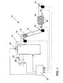
- the catalyst system 10 comprises a NO x storage catalytic converter 16, a precatalyst 18 and various temperature sensors 22. Furthermore, gas sensors 19, 20, 21 are arranged at different positions of the exhaust gas duct 12. These gas sensors serve to detect at least one gas component of an exhaust gas of the internal combustion engine 14 and provide a signal to the engine control unit 24 in accordance with the content of the measured gas component.
- gas sensors 19, 20, 21 are known and may be, for example, lambda probes or NO x sensors.
- All signals provided by the temperature sensors 22 and the gas sensors 19, 20, 21 are forwarded to an engine control unit 24.
- a working mode of the internal combustion engine 14 be controlled by the engine control unit 24. If, for example, a working mode with ⁇ ⁇ 1, ie a rich atmosphere, is required, an oxygen concentration in a suction pipe 26 upstream of the internal combustion engine 14 is lowered, for example by the engine control unit 24 reducing a volume flow of intake air by means of a throttle valve 28 and / or oxygen-poor exhaust gas via an exhaust gas return valve 30 in the suction pipe 26 leads back. In this way, the proportions of reducing gas components CO, HC, H 2 in the exhaust gas increase relative to a proportion of oxygen.
- a desulphurization may for example be determined 16 based on a NO x storage activity of the NOx storage catalytic converter.
- An NO x breakdown characteristic can be detected by means of a gas sensor 21 which detects a NO x concentration behind the NO x storage catalyst 16.
- a sulfur loading of the NO x storage 16 become. If there is a so-called sulfur poisoning of the NO x storage catalytic converter 16, this is initially brought to a temperature which corresponds to or exceeds a minimum desulfurization temperature.
- the current temperature at the NO x storage catalytic converter 16 can be detected, for example, via the temperature sensors 22.
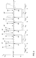
- FIG. 2 shows by way of example a simplified profile of a lambda value in front of and behind the NO x storage catalytic converter 16 during a desulphurisation procedure.
- the solid line represents the predeterminable course of the lambda value in front of the NO x storage catalytic converter 16, which can be detected by means of the gas sensor 20.
- the dashed line represents the course of the lambda value measured with the gas sensor 21 behind the NO x storage catalytic converter 16.
- the internal combustion engine 14 is controlled by means of the engine control unit 24 such that before the NO x storage 16 a predetermined lambda value V m , which is greater than 1, over the duration of a first lean phase T m, 1 sets. Due to a dead volume of the NO x storage catalytic converter 16 and an oxygen storage in these, an increase in the lambda value behind the NO x storage catalytic converter 16 is observed with a time delay. In a range 40 then increases the lambda value behind the NO X storage catalytic converter 16, wherein the slope of the increase is greater, the higher the lambda input V m .
- a change of the operating mode of the internal combustion engine 14 is again initiated, whereby the second lean operating phase T m, 2 begins.
- a reaction of the lambda value after the NO x storage catalytic converter 16 to the changed operating conditions is in turn delayed due to the volume, so that shortly after the start of the second lean phase T m, 2 a minimum is passed which is below the threshold value S f .
- the duration of the phase 46 'in which the reducing agents are completely reacted is reduced in comparison to the phase 46.
- the onset of a lambda drop in the phase 48 'in the direction of the lambda preset V f is observed earlier at the beginning of the rich phase than in the first rich phase T f, 1 .
- This trend continues in the following fat phases.
- an area 46 "observed in the third fat phase T f, 3 is shortened even further compared to the area 46 ', and a drop in the lambda value below 1 in the area 48" is observed even earlier.
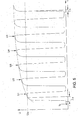
- FIG. 3 shows the course of the time intervals I n determined in the described manner as a function of the number n of rich operating intervals. While the time intervals I n are still very long at the beginning of the desulphurisation procedure, they initially decrease rapidly in the following course to approach a limit later.
- a practically no longer changing interval I n indicates that the desulfurization has been substantially complete.
- a progress check of the desulfurization procedure takes place, for example by calculating the difference of a time interval I n and of a preceding time interval I n-1 .
- the difference of a time interval I n and an immediately preceding time interval I n-1 is determined.
- the interval differences between the first and the second rich operating phase .DELTA.I 2.1 and the fourth and fifth rich operating phase .DELTA.I 5.4 are shown by way of example.
- the size of the interval differences ⁇ I n, n-1 decreases rapidly in the course of the desulfurization procedure.
- a demolition criterion for the desulfurization is given by the fact that a currently determined interval difference ⁇ I n, n-1 falls below a predefinable difference limit ⁇ I G.
- ⁇ I G a multiple undershooting of the predefinable difference limiting value ⁇ I G , for example a drop below twice, as the termination criterion for the desulphurization.
- the determination of a time interval I n can take place, for example, by directly detecting the times of its beginning and its end. This is done, for example, by the probe 20 forwarding the current lambda values to the engine control unit 24 before the NO x storage catalytic converter 16.
- the point in time at which the threshold value S f falls below the lambda value before the NO x storage catalytic converter 16 is recognized by the engine control unit 24 and registered as the start of an interval I n .
- the point in time at which the lambda value measured by the gas probe 21 also reaches the threshold value S f behind the NO x storage catalytic converter 16 is recognized by the engine control unit 24 as the end point of an interval In.
- the engine control unit 24 then calculates the length of the interval In, the difference of the current interval I n and a previous interval I n, ni . If the engine control unit 24 determines that a predetermined abort criterion has been met, for example by falling below a differential limit ⁇ I G , the engine control unit 24 ends the desulfurization procedure by setting the operating conditions of the internal combustion engine 14 in accordance with a by the adjusting means of the throttle valve 28 and the Abgas Wegflußventils 30 Normal operation regulates.
- the length of a time interval I n can also be detected by determining a reducing agent mass m Red, n or an exhaust gas mass m Gas, n , which is lower than the time before the lambda value is sampled before the NO x storage catalytic converter 16 Threshold S f to to descend the lambda value behind the NO x storage catalytic converter 16 below the threshold value S f flows through the exhaust system.
- the calculation of the reducing agent mass m Red, n can be carried out in a manner known per se and not described here in detail from a measured exhaust gas mass flow and a lambda value.
- the monitoring of the desulfurization based on enforced gas masses instead of time intervals has the advantage of increased insensitivity to fluctuating operating conditions.
- the present invention it is provided to initiate a change of operation from a rich operating mode T f, n to a lean operating mode T m, n by the lambda value behind the NO x storage catalytic converter 16 falling below the threshold value S f (points E n in Figure 2).
- the lambda curves in front of and behind the NO x storage catalytic converter 16 according to such dynamically controlled desulfurization are shown in FIG.
- the lengths of the time intervals I n and the lengths of the corresponding fat phases T f, n correspond exactly to one another. Accordingly, the lengths of the fat phases T f, n progressively decrease in the course of the desulfurization process.
- the advantage of this embodiment of the method is a successful suppression of pollutant breakdown, which is accompanied by a drop in the lambda value behind the NO x storage catalyst 16 under 1.
- the execution features described above are not only valid for timed intervals, but also for intervals that are determined on the basis of exhaust or reducing agent mass.
- the progress of the desulfurization process can also be tracked on the basis of the time profile of a lambda probe voltage U n downstream of the NO x storage catalytic converter 16 during the rich operating phases T f, n . Due to the decreasing amount of stored sulfate in the NO x storage catalytic converter 16, with constant lengths of the grease intervals T f, n , an increasingly greater decrease in the lambda value behind the NO x storage catalytic converter 16 is observed below 1 (see FIG. According to the method, the lambda probe voltage U n is detected after a constant presettable interval after the beginning of an n-th rich operating phase T f, n .
- the beginning of the rich operating phase T f, n can again be determined by a drop in the lambda value in front of the NO x storage catalytic converter 16 below the lambda threshold value S f , which has the abovementioned definition.
- the predefinable interval may be a period of time or else the NO X storage catalytic converter 16 enforced, specifiable exhaust mass m gas or reducing agent mass m Red .
- the predefinable interval is selected according to a length of a rich operating phase T f, n .
- the lambda probe voltage U n is therefore detected at the end of a rich operating phase T f, n .
- the course of the lambda probe voltage behind the NO x storage catalytic converter 16 during the desulfurization is shown in FIG. It can be seen here that the length of a time interval I n during a rich operating phase T f, n progressively decreases until the lambda probe voltage U Sf corresponding to the lambda threshold value S f is reached, as the desulfurization time increases. Associated with this is an ever increasing increase in the lambda probe voltage during the rich phases T f, n .
- a suitable termination criterion for the desulfurization can, for example, in turn be provided in that the difference .DELTA.U n, ni a lambda probe voltage U n and a preceding lambda probe voltage U ni a predeterminable difference limit value .DELTA.U G below.
- this embodiment of the present invention is accompanied by an increasing breakthrough of pollutants such as carbon monoxide and unburned hydrocarbons. It is advantageous, however, that in the individual fat phases T f, n a quantitative flushing of the NO x storage catalytic converter 16, which also includes lower catalyst layers, is achieved with the rich exhaust gas atmosphere.
- the desulfurization time can be considerably shortened in this way.
- the monitoring of the desulfurization method according to the invention has been explained on the basis of a profile of the lambda value upstream of the NO x storage catalytic converter 16 in accordance with a predetermined rectangular profile.
- the method according to the invention can be used with equal success if other courses of the lambda value upstream of the NO x storage catalytic converter 16 during desulfurization are taken as the basis, for example in the form of a triangular profile or even more complicated patterns.
- the inventive method provides a sensitive instrument for monitoring the progress of desulfurization.
- the duration of a desulfurization can thus be matched to the actual need.
- a saving of fuel and, on the other hand, thermal damage to the catalyst due to excessive desulphurisation times can be avoided.
- non-sulfur damage to the NO x storage catalyst 16 can be detected. Namely, after completion of the desulfurization process of the present invention not be obtained line with expectations NO X -Speichermeditician again, it can be concluded on a non-sulfur-related damage to the NO x storage catalyst 16, for example to a thermal damage.
Abstract
Claims (20)
- Procédé de désulfuration d'un catalyseur à accumulation de NOx disposé dans un tuyau d'échappement d'un moteur à combustion interne, comprenant au moins une sonde lambda disposée en aval du catalyseur à accumulation de NOx, le moteur à combustion interne fonctionnant pour la désulfuration en alternance en mode de fonctionnement à mélange pauvre avec λ > 1 et en mode de fonctionnement à mélange riche avec λ < 1, caractérisé en ce que la progression de la désulfuration est contrôlée à l'aide de l'allure d'une valeur d'intervalles (In) pendant le processus de désulfuration, l'intervalle (In) s'étendant depuis le début d'une nième phase de fonctionnement riche (Tf,n) jusqu'au dépassement par le bas d'une valeur de seuil lambda prédéfinissable (Sf) en aval du catalyseur à accumulation de NOx (16) et la valeur de seuil lambda prédéfinissable (Sf) étant inférieure à 1 et supérieure à une valeur lambda prédéfinie (Vf) avant le catalyseur à accumulation de NOx (16).
- Procédé selon la revendication 1, caractérisé en ce que le début d'une nième phase de fonctionnement riche (Tf,n) est défini par le dépassement par le bas de la valeur de seuil lambda prédéfinissable (Sf) avant le catalyseur à accumulation de NOx (16).
- Procédé selon l'une quelconque des revendications précédentes, caractérisé en ce qu'un passage d'un mode riche en mode pauvre est déclenché par le dépassement par le bas de la valeur de seuil lambda prédéfinissable (Sf) en aval du catalyseur à accumulation de NOx (16).
- Procédé selon l'une quelconque des revendications précédentes, caractérisé en ce qu'une différence (ΔIn,n-i) d'un niéme intervalle (In) et d'un (n-i)ième intervalle (In-i) précédent est calculée, (i) signifiant un nombre entier positif et la désulfuration étant achevée lors d'au moins un dépassement unique par le bas d'une valeur limite de différence prédéfinissable (ΔIG) par la différence (ΔIn,n-i).
- Procédé selon la revendication 4, caractérisé en ce qu'une différence (△In,n-1) du nième intervalle (In) et d'un (n-1)ième intervalle (In-1) immédiatement précédent est calculée.
- Procédé selon l'une quelconque des revendications 1 à 5, caractérisé en ce que la valeur d'un intervalle (In) correspond à sa durée dans le temps.
- Procédé selon l'une quelconque des revendications 1 à 5, caractérisé en ce que la valeur d'un intervalle (In) correspond à un volume de gaz d'échappement (mGas,n) ayant parcouru le catalyseur à accumulation de NOx (16) pendant la durée de l'intervalle (In).
- Procédé selon la revendication 7, caractérisé en ce que la valeur d'un intervalle (In) correspond à un volume d'agent réducteur (mRed,n) ayant parcouru le catalyseur à accumulation de NOx (16) pendant la durée de l'intervalle (In).
- Procédé de désulfuration d'un catalyseur à accumulation de NOx disposé dans un tuyau d'échappement d'un moteur à combustion interne ayant au moins une sonde lambda disposée en aval du catalyseur à accumulation de NOx, le moteur à combustion interne fonctionnant pour la désulfuration en alternance en mode de fonctionnement à mélange pauvre avec λ > 1 et en mode de fonctionnement à mélange riche avec λ < 1, caractérisé en ce que dans les phases de fonctionnement riche (Tf) de longueur constante, on surveille la progression de la désulfuration à l'aide d'une allure d'une tension de la sonde lambda (Un) en aval du catalyseur à accumulation de NOx (16), laquelle est déterminée après un intervalle prédéfinissable après le début d'une nième phase de fonctionnement riche (Tf,n).
- Procédé selon la revendication 9, caractérisé en ce que le début de la nième phase de fonctionnement riche (Tf,n) est défini par le dépassement par le bas d'une valeur seuil lambda prédéfinissable (Sf) avant le catalyseur à accumulation de NOx (16) et Sf étant inférieure à 1 et supérieure à une valeur lambda prédéfinie (Vf) avant le catalyseur à accumulation de NOx (16).
- Procédé selon l'une quelconque des revendications 9 à 10, caractérisé en ce que l'intervalle prédéfinissable correspond à une durée.
- Procédé selon l'une quelconque des revendications 9 à 10, caractérisé en ce que l'intervalle prédéfinissable correspond à un volume de gaz d'échappement (mGas) ayant parcouru le catalyseur à accumulation de NOx (16).
- Procédé selon l'une quelconque des revendications 9 à 10, caractérisé en ce que l'intervalle prédéfinissable correspond à un volume d'agent réducteur (mRed,n) ayant parcouru le catalyseur à accumulation de NOx (16).
- Procédé selon l'une quelconque des revendications 9 à 13, caractérisé en ce que l'intervalle prédéfinissable correspond à la longueur des phases de fonctionnement riches (Tf).
- Procédé selon l'une quelconque des revendications 9 à 14, caractérisé en ce que l'on calcule une différence (△Un,n-i) entre la tension de la sonde lambda (Un) d'une nième phase de fonctionnement riche (Tf,n) et une tension de la sonde lambda (Un-1) d'une (n-i)ième phase de fonctionnement riche (Tf,n-i) précédente, i signifiant un nombre entier positif, et la désulfuration étant achevée lors d'au moins un dépassement unique par le bas d'une valeur limite de différence prédéfinissable (ΔUG) par la différence (ΔUn,n-i).
- Procédé selon la revendication 15, caractérisé en ce que l'on calcule une différence (△Un,n-1) entre la tension de la sonde lambda (Un) d'une nième phase de fonctionnement riche et une tension de la sonde lambda (Un-1) d'une (n-1)ième phase de fonctionnement riche immédiatement précédente.
- Procédé selon l'une quelconque des revendications précédentes 1 à 16, caractérisé en ce que l'allure dans le temps de la valeur lambda avant le catalyseur à accumulation de NOx (16) pendant la désulfuration correspond à un profil rectangulaire.
- Procédé selon l'une quelconque des revendications 1 à 16, caractérisé en ce que l'allure dans le temps de la valeur lambda avant le catalyseur à accumulation de NOx (16) pendant la désulfuration correspond à un profil triangulaire.
- Procédé selon l'une quelconque des revendications 1 à 18, caractérisé en ce que un passage d'un mode de fonctionnement en mélange pauvre à un mode de fonctionnement en mélange riche du moteur à combustion interne (14) est déclenché par un dépassement d'une valeur de seuil lambda prédéfinissable (Sm) en aval du catalyseur à accumulation de NOx (16), la valeur de seuil lambda prédéfinissable (Sm) étant supérieure à 1 et inférieure à une valeur lambda prédéfinie (Vm) avant le catalyseur à accumulation de NOx (16).
- Procédé selon l'une quelconque des revendications précédentes 1 à 19, caractérisé en ce que le passage entre les modes de fonctionnement en mélange pauvre et en mélange riche est déclenché avec des temps de retard définis après le dépassement par le haut et par le bas de la valeur de seuil supérieure, respectivement inférieure de la valeur lambda existant en aval du catalyseur à accumulation de NOx (16).
Applications Claiming Priority (3)
| Application Number | Priority Date | Filing Date | Title |
|---|---|---|---|
| DE19961165A DE19961165A1 (de) | 1999-12-17 | 1999-12-17 | Verfahren zur Entschwefelung eines in einem Abgaskanal einer Verbrennungskraftmaschine angeordneten NO¶x¶-Speicherkatalysators |
| DE19961165 | 1999-12-17 | ||
| PCT/EP2000/012210 WO2001044630A2 (fr) | 1999-12-17 | 2000-12-05 | PROCEDE DE DESULFURATION D'UN CATALYSEUR ACCUMULATEUR DE NOx MONTE DANS LE CANAL POUR GAZ D'ECHAPPEMENT D'UN MOTEUR A COMBUSTION INTERNE |
Publications (2)
| Publication Number | Publication Date |
|---|---|
| EP1250524A2 EP1250524A2 (fr) | 2002-10-23 |
| EP1250524B1 true EP1250524B1 (fr) | 2006-06-21 |
Family
ID=7933210
Family Applications (1)
| Application Number | Title | Priority Date | Filing Date |
|---|---|---|---|
| EP00989947A Expired - Lifetime EP1250524B1 (fr) | 1999-12-17 | 2000-12-05 | PROCEDE DE DESULFURATION D'UN CATALYSEUR ACCUMULATEUR DE NOx MONTE DANS LE CANAL POUR GAZ D'ECHAPPEMENT D'UN MOTEUR A COMBUSTION INTERNE |
Country Status (7)
| Country | Link |
|---|---|
| US (1) | US6941748B2 (fr) |
| EP (1) | EP1250524B1 (fr) |
| JP (1) | JP4615808B2 (fr) |
| CN (1) | CN1262742C (fr) |
| AU (1) | AU2671801A (fr) |
| DE (2) | DE19961165A1 (fr) |
| WO (1) | WO2001044630A2 (fr) |
Families Citing this family (41)
| Publication number | Priority date | Publication date | Assignee | Title |
|---|---|---|---|---|
| DE10032561A1 (de) * | 2000-07-05 | 2002-07-11 | Volkswagen Ag | Verfahren zur Entschwefelung von wenigstens einem in einem Abgaskanal einer Verbrennungskraftmaschine angeordneten NOx-Speicherkatalysator |
| DE10040010A1 (de) | 2000-08-11 | 2002-02-21 | Bosch Gmbh Robert | Verfahren zur Entschwefelung eines Speichermediums |
| FR2830772B1 (fr) * | 2001-10-12 | 2004-12-24 | Volkswagen Ag | Procedes et dispositif de desulfuration d'un catalyseur a accumulation de nox, implante en aval d'un moteur diesel |
| DE10226873B4 (de) * | 2002-06-12 | 2012-05-31 | Volkswagen Ag | Verfahren zur Steuerung der Betriebsartenwahl einer Verbrennungskraftmaschine |
| GB0220645D0 (en) * | 2002-09-05 | 2002-10-16 | Johnson Matthey Plc | Exhaust system for a lean burn ic engine |
| DE10246505A1 (de) * | 2002-10-05 | 2004-04-15 | Robert Bosch Gmbh | Verfahren zum Betreiben einer Brennkraftmaschine sowie die Brennkraftmaschine selbst |
| DE10307724A1 (de) * | 2003-02-05 | 2004-08-19 | Volkswagen Ag | Kraftfahrzeug mit einem Katalysatorsystem |
| JP3876874B2 (ja) * | 2003-10-28 | 2007-02-07 | トヨタ自動車株式会社 | 触媒再生方法 |
| DE10353597B4 (de) * | 2003-11-12 | 2012-02-23 | Volkswagen Ag | Verfahren und Vorrichtung zur Entschwefelung eines NOx-Speicherkatalysators |
| US7018442B2 (en) * | 2003-11-25 | 2006-03-28 | Caterpillar Inc. | Method and apparatus for regenerating NOx adsorbers |
| US7284368B2 (en) * | 2003-12-02 | 2007-10-23 | Ford Global Technologies Llc | Computer device to control operation during catalyst desulfurization to preserve catalytic function |
| US7263433B2 (en) | 2003-12-02 | 2007-08-28 | Ford Global Technologies, Llc | Computer device to calculate emission control device functionality |
| US20050223698A1 (en) * | 2004-03-31 | 2005-10-13 | Mitsubishi Fuso Truck And Bus Corporation | Exhaust gas cleaning device |
| JP2005291100A (ja) * | 2004-03-31 | 2005-10-20 | Mitsubishi Fuso Truck & Bus Corp | エンジンの排ガス浄化装置 |
| JP4321332B2 (ja) * | 2004-04-01 | 2009-08-26 | トヨタ自動車株式会社 | 内燃機関の排気浄化装置 |
| EP1831509B1 (fr) * | 2004-12-23 | 2010-04-21 | Umicore AG & Co. KG | Procede de surveillance de la capacite d'adsorption d'oxyde d'azote d'un piege d'oxyde d'azote employe en tant que catalyseur de demarrage |
| ATE444114T1 (de) | 2004-12-24 | 2009-10-15 | Umicore Ag & Co Kg | Verfahren zur regeneration eines stickoxid- speicherkatalysators |
| DE102005002289B4 (de) * | 2005-01-17 | 2007-04-19 | J. Eberspächer GmbH & Co. KG | Abgasbehandlungssystem |
| US7481046B2 (en) | 2005-02-28 | 2009-01-27 | Ford Global Technologies, Llc | Method of desulfating a NOx storage and conversion device |
| JP4572709B2 (ja) * | 2005-03-18 | 2010-11-04 | トヨタ自動車株式会社 | 内燃機関の排気浄化システム |
| DE102005029338A1 (de) * | 2005-06-24 | 2007-02-08 | Emitec Gesellschaft Für Emissionstechnologie Mbh | Verfahren zum Betrieb einer Partikelfalle sowie Vorrichtung zur Durchführung des Verfahrens |
| DE102005034344A1 (de) * | 2005-07-22 | 2007-01-25 | Umicore Ag & Co. Kg | Verfahren zur Reaktivierung thermisch gealterter Stickoxid-Speicherkatalysatoren |
| FR2897102B1 (fr) * | 2006-02-09 | 2012-06-01 | Peugeot Citroen Automobiles Sa | Systeme et procede d'elimination de sox (oxyde de soufre), et generateur de requetes pour ce systeme |
| DE102006048905A1 (de) * | 2006-10-17 | 2008-04-30 | Robert Bosch Gmbh | Verfahren zur Entschwefelung eines Speicherkatalysators und Vorrichtung zur Durchführung des Verfahrens |
| US7654076B2 (en) * | 2006-11-07 | 2010-02-02 | Cummins, Inc. | System for controlling absorber regeneration |
| US7533523B2 (en) * | 2006-11-07 | 2009-05-19 | Cummins, Inc. | Optimized desulfation trigger control for an adsorber |
| US7594392B2 (en) * | 2006-11-07 | 2009-09-29 | Cummins, Inc. | System for controlling adsorber regeneration |
| US7707826B2 (en) | 2006-11-07 | 2010-05-04 | Cummins, Inc. | System for controlling triggering of adsorber regeneration |
| US7654079B2 (en) * | 2006-11-07 | 2010-02-02 | Cummins, Inc. | Diesel oxidation catalyst filter heating system |
| US8266897B2 (en) * | 2006-12-28 | 2012-09-18 | Caterpillar Inc. | Low temperature emission system having turbocharger bypass |
| JP4803107B2 (ja) * | 2007-05-15 | 2011-10-26 | トヨタ自動車株式会社 | 内燃機関の排気浄化装置 |
| DE102008058008B3 (de) * | 2008-11-19 | 2010-02-18 | Continental Automotive Gmbh | Vorrichtung zum Betreiben einer Brennkraftmaschine |
| EP2415984B1 (fr) * | 2009-03-31 | 2015-12-16 | Toyota Jidosha Kabushiki Kaisha | Système de purification de gaz d'échappement de moteur à combustion interne |
| JP5067478B2 (ja) * | 2009-05-15 | 2012-11-07 | トヨタ自動車株式会社 | 内燃機関の排気浄化装置 |
| US20110185708A1 (en) * | 2010-01-29 | 2011-08-04 | Eaton Corporation | Adaptive Desulfation Control Algorithm |
| CN103764961B (zh) * | 2012-08-28 | 2016-01-13 | 丰田自动车株式会社 | 火花点火式内燃机的排气净化装置 |
| DE102018004892A1 (de) * | 2018-06-20 | 2019-12-24 | Daimler Ag | Verfahren zum Entschwefeln eines Stickoxid-Speicherkatalysators |
| US10920645B2 (en) | 2018-08-02 | 2021-02-16 | Ford Global Technologies, Llc | Systems and methods for on-board monitoring of a passive NOx adsorption catalyst |
| CN110700955B (zh) * | 2018-12-28 | 2020-12-08 | 长城汽车股份有限公司 | 汽油发动机催化器的过量空气系数控制方法及装置 |
| US10954873B2 (en) * | 2019-03-01 | 2021-03-23 | Fca Us Llc | Engine lambda dynamic control strategy for exhaust emission reduction |
| CN110585896B (zh) * | 2019-10-30 | 2024-02-13 | 苏州仕净科技股份有限公司 | 一种船舶废气干式脱硫系统 |
Family Cites Families (19)
| Publication number | Priority date | Publication date | Assignee | Title |
|---|---|---|---|---|
| DE4342656C2 (de) * | 1992-12-14 | 2003-07-31 | Mazda Motor | Luft-/Kraftstoff-Regelung für einen Verbrennungsmotor |
| JP3456058B2 (ja) * | 1995-02-10 | 2003-10-14 | 株式会社デンソー | 触媒の劣化検出装置及び排気浄化装置の異常検出装置 |
| US5704339A (en) * | 1996-04-26 | 1998-01-06 | Ford Global Technologies, Inc. | method and apparatus for improving vehicle fuel economy |
| JPH1071325A (ja) * | 1996-06-21 | 1998-03-17 | Ngk Insulators Ltd | エンジン排ガス系の制御方法および触媒/吸着手段の劣化検出方法 |
| US5771685A (en) | 1996-10-16 | 1998-06-30 | Ford Global Technologies, Inc. | Method for monitoring the performance of a NOx trap |
| DE19705335C1 (de) * | 1997-02-12 | 1998-09-17 | Siemens Ag | Verfahren zur Regeneration eines Speicherkatalysators |
| GB2324052A (en) * | 1997-04-11 | 1998-10-14 | Ford Motor Co | Heating of a storage trap |
| EP0892158B1 (fr) * | 1997-07-19 | 2003-02-12 | Volkswagen Aktiengesellschaft | Procédé et dispositif de surveillance de désulfuration de catalyseurs de stockage de NOx |
| US5974788A (en) * | 1997-08-29 | 1999-11-02 | Ford Global Technologies, Inc. | Method and apparatus for desulfating a nox trap |
| DE19747222C1 (de) * | 1997-10-25 | 1999-03-04 | Daimler Benz Ag | Verbrennungsmotoranlage mit Stickoxid-Speicherkatalysator und Betriebsverfahren hierfür |
| DE19800665C1 (de) * | 1998-01-10 | 1999-07-01 | Degussa | Verfahren zum Betreiben eines Stickoxid-Speicherkatalysators |
| DE19802631C1 (de) * | 1998-01-24 | 1999-07-22 | Daimler Chrysler Ag | Verfahren und Einrichtung zum Reinigen von Abgasen eines Verbrennungsmotors |
| DE19813654A1 (de) * | 1998-03-27 | 1999-09-30 | Degussa | Verfahren zum Betreiben einer Abgasreinigungsanlage enthaltend eine Schwefelfalle und einen Stickoxid-Speicherkatalysator |
| DE19816175A1 (de) * | 1998-04-14 | 1999-10-21 | Degussa | Verfahren zur Überprüfung der Funktionstüchtigkeit eines Stickoxid-Speicherkatalysators |
| JP3997599B2 (ja) * | 1998-04-27 | 2007-10-24 | 株式会社デンソー | 内燃機関の空燃比制御装置 |
| SE514288C2 (sv) * | 1998-05-27 | 2001-02-05 | Volvo Ab | Anordning och förfarande för svavelregenerering av NOx- adsorberande katalysator |
| DE19827195A1 (de) * | 1998-06-18 | 1999-12-23 | Volkswagen Ag | Verfahren zur De-Sulfatierung eines NOx-Speicherkatalysators |
| US6497092B1 (en) * | 1999-03-18 | 2002-12-24 | Delphi Technologies, Inc. | NOx absorber diagnostics and automotive exhaust control system utilizing the same |
| DE19918756A1 (de) | 1999-04-24 | 2000-10-26 | Volkswagen Ag | Anordnung zur Reinigung eines Abgases einer Verbrennungsmaschine und Verfahren zum Betrieb einer solchen Anordnung |
-
1999
- 1999-12-17 DE DE19961165A patent/DE19961165A1/de not_active Withdrawn
-
2000
- 2000-12-05 AU AU26718/01A patent/AU2671801A/en not_active Abandoned
- 2000-12-05 CN CNB008172730A patent/CN1262742C/zh not_active Expired - Fee Related
- 2000-12-05 WO PCT/EP2000/012210 patent/WO2001044630A2/fr active IP Right Grant
- 2000-12-05 US US10/168,157 patent/US6941748B2/en not_active Expired - Lifetime
- 2000-12-05 JP JP2001545697A patent/JP4615808B2/ja not_active Expired - Fee Related
- 2000-12-05 EP EP00989947A patent/EP1250524B1/fr not_active Expired - Lifetime
- 2000-12-05 DE DE50013067T patent/DE50013067D1/de not_active Expired - Lifetime
Also Published As
| Publication number | Publication date |
|---|---|
| CN1262742C (zh) | 2006-07-05 |
| WO2001044630A3 (fr) | 2001-12-06 |
| US6941748B2 (en) | 2005-09-13 |
| EP1250524A2 (fr) | 2002-10-23 |
| JP4615808B2 (ja) | 2011-01-19 |
| WO2001044630A2 (fr) | 2001-06-21 |
| US20030131591A1 (en) | 2003-07-17 |
| JP2003518578A (ja) | 2003-06-10 |
| CN1411533A (zh) | 2003-04-16 |
| AU2671801A (en) | 2001-06-25 |
| DE50013067D1 (de) | 2006-08-03 |
| DE19961165A1 (de) | 2001-08-02 |
Similar Documents
| Publication | Publication Date | Title |
|---|---|---|
| EP1250524B1 (fr) | PROCEDE DE DESULFURATION D'UN CATALYSEUR ACCUMULATEUR DE NOx MONTE DANS LE CANAL POUR GAZ D'ECHAPPEMENT D'UN MOTEUR A COMBUSTION INTERNE | |
| DE10040554B4 (de) | Verfahren zum Betrieb einer Abgasreinigungsanlage mit Partikelfilter und Stickoxidspeicher | |
| DE102006046455B4 (de) | Verfahren zum Regenerieren eines NOx-absorbierenden Katalysators | |
| EP1192343B1 (fr) | PROCEDE PERMETTANT DE LANCER ET DE SURVEILLER LA DESULFURATION D'AU MOINS UN CATALYSEUR A STOCKAGE DE NOx PLACE DANS UN TUYAU D'ECHAPPEMENT D'UN MOTEUR A COMBUSTION INTERNE | |
| WO2001055564A2 (fr) | Procede et dispositif pour reguler le fonctionnement d'un catalyseur accumulateur de nox place dans le canal d'echappement des gaz d'un moteur a combustion interne | |
| DE10114456A1 (de) | Vorrichtung und Verfahren zur Koordination von abgasrelevanten Maßnahmen | |
| EP1301698B1 (fr) | Procede pour la desulfuration d'au moins un catalyseur de stockage des nox place dans un conduit d'echappement d'un moteur a combustion interne | |
| EP1190164B1 (fr) | PROCEDE DE DETECTION D'UNE ALTERATION D'AU MOINS UN CATALYSEUR ACCUMULATEUR DE NOx DISPOSE DANS UN CONDUIT DE GAZ D'ECHAPPEMENT D'UN MOTEUR A COMBUSTION INTERNE | |
| DE10160704B4 (de) | Verfahren zum Betrieb von Abgasreinigungsvorrichtungen | |
| DE10115962B4 (de) | Verfahren zur Entschwefelung eines im Abgasstrang einer Verbrennungskraftmaschine angeordneten NOx-Speicherkatalysators | |
| EP1160425B1 (fr) | Méthode et procédé pour la régénération d'un catalyseur à stockage de NOx | |
| DE10123148B4 (de) | Verfahren und Vorrichtung zur Entschwefelung eines Vorkatalysators | |
| DE10023079B4 (de) | Vorrichtung und Verfahren zur Steuerung einer NOx-Regeneration eines im Abgasstrang einer Verbrennungskraftmaschine angeordneten NOx-Speicherkatalysators | |
| EP1209332B1 (fr) | Méthode et appareil de régénération d'un catalyseur accumulateur de NOx | |
| DE10330367A1 (de) | Verfahren und Vorrichtung zur Entschwefelung eines Katalysators | |
| EP1244871B1 (fr) | Dispositif et procede pour commander la vitesse de reinjection de gaz d'echappement d'un dispositif de reinjection de gaz d'echappement pour moteurs a combustion interne pendant le fonctionnement en mode melange pauvre | |
| EP1252420B1 (fr) | Dispositif et procede de commande d'une regeneration de nox d'un catalyseur accumulateur de nox | |
| DE10102132B4 (de) | Verfahren und Vorrichtung zur Entschwefelung eines NOx-Speicherkatalysators | |
| DE102009045088B4 (de) | Verfahren zur Steuerung eines Verbrennungsmotors in Verbindung mit einer exothermen Regeneration einer Abgasnachbehandlungkomponente | |
| DE10130053B4 (de) | Verfahren und Vorrichtung zur Entschwefelung eines NOX-Speicherkatalysators | |
| DE10036390B4 (de) | Verfahren und Vorrichtung zur Entschwefelung eines NOx-Speicherkatalysators | |
| DE10057938A1 (de) | Verfahren und Vorrichtung zur Regeneration eines NOx-Speicherkatalysators | |
| DE102004060125B4 (de) | Verfahren zur Steuerung der Be- und Entladung des Sauerstoffspeichers eines Abgaskatalysators | |
| EP1188915B1 (fr) | Procédé de réglage de la régénération d'un catalyseur d'accumulation de NOx | |
| EP1365131B1 (fr) | Procédé de reglage d'un catalyseur d'accumulation de NOx |
Legal Events
| Date | Code | Title | Description |
|---|---|---|---|
| PUAI | Public reference made under article 153(3) epc to a published international application that has entered the european phase |
Free format text: ORIGINAL CODE: 0009012 |
|
| 17P | Request for examination filed |
Effective date: 20020717 |
|
| AK | Designated contracting states |
Kind code of ref document: A2 Designated state(s): AT BE CH CY DE DK ES FI FR GB GR IE IT LI LU MC NL PT SE TR |
|
| AX | Request for extension of the european patent |
Free format text: AL;LT;LV;MK;RO;SI |
|
| RIN1 | Information on inventor provided before grant (corrected) |
Inventor name: HAHN, HERMANN Inventor name: HOEHNE, JUERGEN Inventor name: GOEBEL, ULRICH Inventor name: POTT, EKKEHARD |
|
| RAP1 | Party data changed (applicant data changed or rights of an application transferred) |
Owner name: OMG AG & CO. KG Owner name: VOLKSWAGEN AKTIENGESELLSCHAFT |
|
| RAP1 | Party data changed (applicant data changed or rights of an application transferred) |
Owner name: UMICORE AG & CO. KG Owner name: VOLKSWAGEN AKTIENGESELLSCHAFT |
|
| RBV | Designated contracting states (corrected) |
Designated state(s): DE FR GB |
|
| 17Q | First examination report despatched |
Effective date: 20041209 |
|
| GRAP | Despatch of communication of intention to grant a patent |
Free format text: ORIGINAL CODE: EPIDOSNIGR1 |
|
| RIN1 | Information on inventor provided before grant (corrected) |
Inventor name: HAHN, HERMANN Inventor name: POTT, EKKEHARD Inventor name: HOEHNE, JUERGEN Inventor name: GOEBEL, ULRICH |
|
| RTI1 | Title (correction) |
Free format text: METHOD FOR DESULPHURISATION OF AN NOX ACCUMULATOR-CATALYST ARRANGED IN AN EXHAUST SYSTEM OF AN INTERNAL COMBUSTION ENGINE |
|
| GRAS | Grant fee paid |
Free format text: ORIGINAL CODE: EPIDOSNIGR3 |
|
| GRAA | (expected) grant |
Free format text: ORIGINAL CODE: 0009210 |
|
| RIN1 | Information on inventor provided before grant (corrected) |
Inventor name: GOEBEL, ULRICH Inventor name: POTT, EKKEHARD Inventor name: HAHN, HERMANN Inventor name: HOEHNE, JUERGEN |
|
| AK | Designated contracting states |
Kind code of ref document: B1 Designated state(s): DE FR GB |
|
| REG | Reference to a national code |
Ref country code: GB Ref legal event code: FG4D Free format text: NOT ENGLISH |
|
| REF | Corresponds to: |
Ref document number: 50013067 Country of ref document: DE Date of ref document: 20060803 Kind code of ref document: P |
|
| GBT | Gb: translation of ep patent filed (gb section 77(6)(a)/1977) |
Effective date: 20060924 |
|
| PLBE | No opposition filed within time limit |
Free format text: ORIGINAL CODE: 0009261 |
|
| STAA | Information on the status of an ep patent application or granted ep patent |
Free format text: STATUS: NO OPPOSITION FILED WITHIN TIME LIMIT |
|
| EN | Fr: translation not filed | ||
| 26N | No opposition filed |
Effective date: 20070322 |
|
| PG25 | Lapsed in a contracting state [announced via postgrant information from national office to epo] |
Ref country code: FR Free format text: LAPSE BECAUSE OF FAILURE TO SUBMIT A TRANSLATION OF THE DESCRIPTION OR TO PAY THE FEE WITHIN THE PRESCRIBED TIME-LIMIT Effective date: 20070504 |
|
| PG25 | Lapsed in a contracting state [announced via postgrant information from national office to epo] |
Ref country code: FR Free format text: LAPSE BECAUSE OF FAILURE TO SUBMIT A TRANSLATION OF THE DESCRIPTION OR TO PAY THE FEE WITHIN THE PRESCRIBED TIME-LIMIT Effective date: 20060621 |
|
| PGFP | Annual fee paid to national office [announced via postgrant information from national office to epo] |
Ref country code: GB Payment date: 20161228 Year of fee payment: 17 |
|
| PGFP | Annual fee paid to national office [announced via postgrant information from national office to epo] |
Ref country code: DE Payment date: 20161231 Year of fee payment: 17 |
|
| REG | Reference to a national code |
Ref country code: DE Ref legal event code: R119 Ref document number: 50013067 Country of ref document: DE |
|
| GBPC | Gb: european patent ceased through non-payment of renewal fee |
Effective date: 20171205 |
|
| PG25 | Lapsed in a contracting state [announced via postgrant information from national office to epo] |
Ref country code: DE Free format text: LAPSE BECAUSE OF NON-PAYMENT OF DUE FEES Effective date: 20180703 |
|
| PG25 | Lapsed in a contracting state [announced via postgrant information from national office to epo] |
Ref country code: GB Free format text: LAPSE BECAUSE OF NON-PAYMENT OF DUE FEES Effective date: 20171205 |