EP1209332B1 - Méthode et appareil de régénération d'un catalyseur accumulateur de NOx - Google Patents
Méthode et appareil de régénération d'un catalyseur accumulateur de NOx Download PDFInfo
- Publication number
- EP1209332B1 EP1209332B1 EP20010250407 EP01250407A EP1209332B1 EP 1209332 B1 EP1209332 B1 EP 1209332B1 EP 20010250407 EP20010250407 EP 20010250407 EP 01250407 A EP01250407 A EP 01250407A EP 1209332 B1 EP1209332 B1 EP 1209332B1
- Authority
- EP
- European Patent Office
- Prior art keywords
- regeneration
- signal
- exhaust gas
- internal combustion
- combustion engine
- Prior art date
- Legal status (The legal status is an assumption and is not a legal conclusion. Google has not performed a legal analysis and makes no representation as to the accuracy of the status listed.)
- Expired - Lifetime
Links
Images

Classifications
-
- F—MECHANICAL ENGINEERING; LIGHTING; HEATING; WEAPONS; BLASTING
- F02—COMBUSTION ENGINES; HOT-GAS OR COMBUSTION-PRODUCT ENGINE PLANTS
- F02D—CONTROLLING COMBUSTION ENGINES
- F02D41/00—Electrical control of supply of combustible mixture or its constituents
- F02D41/02—Circuit arrangements for generating control signals
- F02D41/14—Introducing closed-loop corrections
- F02D41/1438—Introducing closed-loop corrections using means for determining characteristics of the combustion gases; Sensors therefor
- F02D41/1439—Introducing closed-loop corrections using means for determining characteristics of the combustion gases; Sensors therefor characterised by the position of the sensor
-
- F—MECHANICAL ENGINEERING; LIGHTING; HEATING; WEAPONS; BLASTING
- F01—MACHINES OR ENGINES IN GENERAL; ENGINE PLANTS IN GENERAL; STEAM ENGINES
- F01N—GAS-FLOW SILENCERS OR EXHAUST APPARATUS FOR MACHINES OR ENGINES IN GENERAL; GAS-FLOW SILENCERS OR EXHAUST APPARATUS FOR INTERNAL COMBUSTION ENGINES
- F01N13/00—Exhaust or silencing apparatus characterised by constructional features ; Exhaust or silencing apparatus, or parts thereof, having pertinent characteristics not provided for in, or of interest apart from, groups F01N1/00 - F01N5/00, F01N9/00, F01N11/00
- F01N13/009—Exhaust or silencing apparatus characterised by constructional features ; Exhaust or silencing apparatus, or parts thereof, having pertinent characteristics not provided for in, or of interest apart from, groups F01N1/00 - F01N5/00, F01N9/00, F01N11/00 having two or more separate purifying devices arranged in series
-
- F—MECHANICAL ENGINEERING; LIGHTING; HEATING; WEAPONS; BLASTING
- F01—MACHINES OR ENGINES IN GENERAL; ENGINE PLANTS IN GENERAL; STEAM ENGINES
- F01N—GAS-FLOW SILENCERS OR EXHAUST APPARATUS FOR MACHINES OR ENGINES IN GENERAL; GAS-FLOW SILENCERS OR EXHAUST APPARATUS FOR INTERNAL COMBUSTION ENGINES
- F01N3/00—Exhaust or silencing apparatus having means for purifying, rendering innocuous, or otherwise treating exhaust
- F01N3/08—Exhaust or silencing apparatus having means for purifying, rendering innocuous, or otherwise treating exhaust for rendering innocuous
- F01N3/0807—Exhaust or silencing apparatus having means for purifying, rendering innocuous, or otherwise treating exhaust for rendering innocuous by using absorbents or adsorbents
- F01N3/0814—Exhaust or silencing apparatus having means for purifying, rendering innocuous, or otherwise treating exhaust for rendering innocuous by using absorbents or adsorbents combined with catalytic converters, e.g. NOx absorption/storage reduction catalysts
-
- F—MECHANICAL ENGINEERING; LIGHTING; HEATING; WEAPONS; BLASTING
- F02—COMBUSTION ENGINES; HOT-GAS OR COMBUSTION-PRODUCT ENGINE PLANTS
- F02D—CONTROLLING COMBUSTION ENGINES
- F02D41/00—Electrical control of supply of combustible mixture or its constituents
- F02D41/02—Circuit arrangements for generating control signals
- F02D41/021—Introducing corrections for particular conditions exterior to the engine
- F02D41/0235—Introducing corrections for particular conditions exterior to the engine in relation with the state of the exhaust gas treating apparatus
- F02D41/027—Introducing corrections for particular conditions exterior to the engine in relation with the state of the exhaust gas treating apparatus to purge or regenerate the exhaust gas treating apparatus
- F02D41/0275—Introducing corrections for particular conditions exterior to the engine in relation with the state of the exhaust gas treating apparatus to purge or regenerate the exhaust gas treating apparatus the exhaust gas treating apparatus being a NOx trap or adsorbent
-
- F—MECHANICAL ENGINEERING; LIGHTING; HEATING; WEAPONS; BLASTING
- F01—MACHINES OR ENGINES IN GENERAL; ENGINE PLANTS IN GENERAL; STEAM ENGINES
- F01N—GAS-FLOW SILENCERS OR EXHAUST APPARATUS FOR MACHINES OR ENGINES IN GENERAL; GAS-FLOW SILENCERS OR EXHAUST APPARATUS FOR INTERNAL COMBUSTION ENGINES
- F01N3/00—Exhaust or silencing apparatus having means for purifying, rendering innocuous, or otherwise treating exhaust
- F01N3/08—Exhaust or silencing apparatus having means for purifying, rendering innocuous, or otherwise treating exhaust for rendering innocuous
- F01N3/0807—Exhaust or silencing apparatus having means for purifying, rendering innocuous, or otherwise treating exhaust for rendering innocuous by using absorbents or adsorbents
- F01N3/0828—Exhaust or silencing apparatus having means for purifying, rendering innocuous, or otherwise treating exhaust for rendering innocuous by using absorbents or adsorbents characterised by the absorbed or adsorbed substances
- F01N3/0842—Nitrogen oxides
-
- F—MECHANICAL ENGINEERING; LIGHTING; HEATING; WEAPONS; BLASTING
- F02—COMBUSTION ENGINES; HOT-GAS OR COMBUSTION-PRODUCT ENGINE PLANTS
- F02D—CONTROLLING COMBUSTION ENGINES
- F02D2200/00—Input parameters for engine control
- F02D2200/02—Input parameters for engine control the parameters being related to the engine
- F02D2200/08—Exhaust gas treatment apparatus parameters
- F02D2200/0802—Temperature of the exhaust gas treatment apparatus
- F02D2200/0804—Estimation of the temperature of the exhaust gas treatment apparatus
-
- F—MECHANICAL ENGINEERING; LIGHTING; HEATING; WEAPONS; BLASTING
- F02—COMBUSTION ENGINES; HOT-GAS OR COMBUSTION-PRODUCT ENGINE PLANTS
- F02D—CONTROLLING COMBUSTION ENGINES
- F02D2200/00—Input parameters for engine control
- F02D2200/02—Input parameters for engine control the parameters being related to the engine
- F02D2200/08—Exhaust gas treatment apparatus parameters
- F02D2200/0806—NOx storage amount, i.e. amount of NOx stored on NOx trap
-
- F—MECHANICAL ENGINEERING; LIGHTING; HEATING; WEAPONS; BLASTING
- F02—COMBUSTION ENGINES; HOT-GAS OR COMBUSTION-PRODUCT ENGINE PLANTS
- F02D—CONTROLLING COMBUSTION ENGINES
- F02D2200/00—Input parameters for engine control
- F02D2200/02—Input parameters for engine control the parameters being related to the engine
- F02D2200/08—Exhaust gas treatment apparatus parameters
- F02D2200/0814—Oxygen storage amount
-
- F—MECHANICAL ENGINEERING; LIGHTING; HEATING; WEAPONS; BLASTING
- F02—COMBUSTION ENGINES; HOT-GAS OR COMBUSTION-PRODUCT ENGINE PLANTS
- F02D—CONTROLLING COMBUSTION ENGINES
- F02D2200/00—Input parameters for engine control
- F02D2200/02—Input parameters for engine control the parameters being related to the engine
- F02D2200/08—Exhaust gas treatment apparatus parameters
- F02D2200/0816—Oxygen storage capacity
-
- F—MECHANICAL ENGINEERING; LIGHTING; HEATING; WEAPONS; BLASTING
- F02—COMBUSTION ENGINES; HOT-GAS OR COMBUSTION-PRODUCT ENGINE PLANTS
- F02D—CONTROLLING COMBUSTION ENGINES
- F02D41/00—Electrical control of supply of combustible mixture or its constituents
- F02D41/02—Circuit arrangements for generating control signals
- F02D41/14—Introducing closed-loop corrections
- F02D41/1438—Introducing closed-loop corrections using means for determining characteristics of the combustion gases; Sensors therefor
- F02D41/1444—Introducing closed-loop corrections using means for determining characteristics of the combustion gases; Sensors therefor characterised by the characteristics of the combustion gases
- F02D41/1454—Introducing closed-loop corrections using means for determining characteristics of the combustion gases; Sensors therefor characterised by the characteristics of the combustion gases the characteristics being an oxygen content or concentration or the air-fuel ratio
Definitions
- the invention relates to methods for carrying out a regeneration of a NO x storage catalytic converter in an exhaust line of an internal combustion engine and to devices for carrying out the regeneration with the features mentioned in the preambles of the independent claims 1 to 3 or 20 or 21.
- the internal combustion engine is temporarily switched to a rich or stoichiometric working mode ( ⁇ ⁇ 1).
- a reducing agent mass flow of the exhaust gas increases, the nitrate incorporated nitrogen oxides are desorbed and catalytically reacted on the NO x storage catalyst with simultaneous oxidation of CO and HC.
- the invention is therefore based on the object to provide a method for NO x regeneration of a NO x storage catalyst available, which is optimized in terms of the lowest possible reducing agent emission and at the same time ensures complete regeneration of the storage catalyst.
- the fastest possible procedure of the method ie short regeneration periods, should be ensured. It is further intended to provide a device which is suitable and advantageous for carrying out the method.
- the achievement of the predetermined signal threshold value can be determined in advance with sufficient reliability.
- This makes it possible to take into account the time span corresponding to the exhaust gas running time between the internal combustion engine and the NO x storage catalytic converter - hereinafter referred to simply as the exhaust gas flow time - so that the NO x regeneration can be stopped in good time, that is to say before the occurrence of a reductant breakthrough.
- the method thus allows a reduction of CO and HC emission and minimization of a need for NO x regeneration additional fuel consumption.
- the extrapolation of the oxygen-dependent signal of the measuring device is carried out according to an advantageous embodiment of the method based on current operating parameters of the internal combustion engine and / or the exhaust system. These may include, for example, a current air-fuel mixture (combustion lambda) supplied to the internal combustion engine and / or an exhaust gas mass flow and / or an exhaust gas temperature and / or a catalyst temperature.
- a current air-fuel mixture combustion lambda
- the accuracy of the extrapolation can be further increased by taking into account a behavioral model of the NO x storage catalytic converter.
- a behavioral model can be, for example, the course of a regeneration rate as a function of the current reducing agent mass flow and / or the catalyst temperature include.
- the behavioral model can also take into account the waveform measured during the current regeneration.
- An advantageous further development of the method can also be achieved by extrapolating the signal taking into account a behavioral model of the oxygen-sensitive measuring device.
- a behavioral model of the oxygen-sensitive measuring device ie a time delay, with which the measuring device displays changed exhaust gas conditions, but also a current, measured about an internal resistance, temperature of the measuring device can be considered.
- the exhaust gas flow time is preferably provided to calculate these using current operating parameters of the internal combustion engine. It can be used on known operating parameters such as engine load, speed or exhaust gas temperature or other suitable data.
- a preferred embodiment of the method provides for setting limits for different operating conditions of the internal combustion engine and / or the exhaust system and suppressing the extrapolation if these limits are not met.
- limit values for the exhaust gas mass flow and / or for the temperature of the NO x storage catalytic converter are expedient, since the regeneration rates are too unstable if the exhaust gas mass flows are too high or the catalyst temperatures are too low to be able to be extrapolated with sufficient reliability.
- the signal extrapolation can advantageously also be suppressed if there are operating point-dependent disturbing influences which influence an irregular NO x regeneration. This is the case, for example, with a fuel cut of the internal combustion engine.
- the extrapolation is not carried out during the entire regeneration period of the storage catalytic converter, but only after elapse of a predetermined time after the beginning of the regeneration and / or flow rate of a given exhaust gas mass and / or after exceeding a predetermined minimum threshold of the signal of the measuring device.
- the extrapolation according to the invention makes it possible, in this aspect of the invention, to take into account the exhaust gas flow time during the change of the combustion lambda during the regeneration, so that it is possible to react to an expected signal height to a certain extent with foresight.
- the method thus allows a reduction in CO and HC emission and minimization of a need for the NO x regeneration additional fuel consumption.
- the (theoretical) achievement of the signal threshold value prescribed for a regeneration interruption is determined in advance.
- the regeneration can be stopped in time, that is, before the occurrence of a Reduktionsstoff bebruches.
- the increase can take place after the expiry of a predefinable portion of a total regeneration duration determined by the extrapolation. It is even more advantageous to increase the combustion lambda on reaching a second predetermined signal threshold value by the projected sensor signal taking into account the exhaust gas flow time, the second signal threshold is usefully smaller than the first signal threshold, if it is a probe voltage.
- the increase of the combustion lambda before the regeneration end causes a reduction of a reducing agent mass flow at a time at which only small amounts of stored nitrogen oxides in the storage catalyst are available for the conversion of the reducing agent.
- the risk of reducing agent breakthrough at the end of the regeneration is thus further reduced. It has proven particularly useful to increase the lambda Lambda values of 0.94 to 0.99, in particular 0.95 to 0.98.
- the combustion lambda of the internal combustion engine is lowered below a previous lambda value until the projected sensor signal, taking into account the exhaust gas running time, reaches a third predetermined signal threshold value.
- combustion lambda values of 0.6 to 0.9, in particular 0.7 to 0.8 have proven particularly useful.
- the NO x storage catalytic converter thus becomes with a comparatively very rich exhaust gas atmosphere acted as long as the memory still has a marked by the third signal threshold minimum loading of nitrogen oxides.
- an efficiency of the NO x conversion is increased, the regeneration duration is shortened and, ultimately, the additional fuel consumption to be expended for the regeneration is minimized.
- threshold values whose exceeding-triggered by the extrapolated sensor signal further variations of the combustion lambda. Additional threshold values may, for example, take into account an otherwise determined aging state of the storage catalytic converter. The various increases and / or reductions of the internal combustion engine to be supplied air-fuel mixture can also be done gradually or even continuously.
- the devices according to the invention comprise means with which the described method steps can be carried out.
- the means comprise a control unit in which an algorithm for controlling the method steps is stored in digital form.
- This control unit can advantageously also be integrated in an engine control unit of the vehicle.
- the oxygen-sensitive measuring device may be a lambda probe arranged downstream of the NO x storage catalytic converter, in particular a broadband or a step response lambda probe, or an NO x sensor having a lambda output signal.
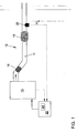
- the Indian FIG. 1 shown internal combustion engine 10 is associated with a generally designated 12 exhaust system.
- the exhaust system 12 includes an exhaust passage 14, in which a arranged in a near-engine position precatalyst 16 and a large-volume NO x storage 18 is arranged.
- the exhaust duct 14 usually houses various gas and / or temperature sensors (not shown) for controlling the internal combustion engine 10.
- Shown here is merely an oxygen-sensitive measuring device 20, which is arranged downstream of the NO x storage 18.
- the measuring device 20 may be, for example, a lambda probe or an NO x sensor, which is equipped with a Lambdamessfunktion. In any case, the measuring device 20 provides a dependent of an oxygen content of the exhaust gas signal U ⁇ .
- This signal U ⁇ is transmitted to an engine control unit 22, in which it is digitized and further processed. Further, the operating state of the internal combustion engine 10 information concerning also found in the engine control unit 22.
- a control unit 24 is integrated, in which an algorithm for performing the method for NO x regeneration of the NO x storage 18 is stored.
- the engine control unit 22 and the control unit 24 are capable of influencing at least one operating parameter of the internal combustion engine 10, in particular an air-fuel mixture (combustion lambda) to be supplied, as a function of the signal U ⁇ of the measuring device in a manner to be explained.
- FIG. 2 shows the time course of various parameters of the internal combustion engine 10 and the exhaust system 12 during a NO x regeneration of the NO x storage catalytic converter 18, which is carried out according to a conventional method.
- the internal combustion engine 10 is in a lean mode of operation in which it is supplied with an oxygen-rich air-fuel mixture with ⁇ M >> 1 (graph 100).
- the exhaust gas contains an excess of nitrogen oxides NO x , which is not complete by the precatalyst 16 can be converted.
- NO x is therefore stored in the NO x storage 18, the NO x load continuously increases (Graph 102). Based on a suitable criterion, a NO x regeneration need is recognized at a time t A.
- the internal combustion engine Consequently, 10 is switched by influencing the engine control unit 22 in a rich operating mode with ⁇ F ⁇ 1.
- ⁇ F ⁇ 1 As a result of the now increased mass flow of reducing agents CO and HC in the exhaust is - the x desorbed NO x storing catalyst 18 embedded NO and nitrogen reduced.
- a decrease in the NO x charge (graph 102) of the storage catalytic converter 18 is only noticeable after a certain time delay after switching the internal combustion engine 10, since at the time t A the exhaust duct 14 is still filled with lean exhaust gas, which initially still the storage catalytic converter 18 must happen before the reducing agents reach it.
- the course of the NO x regeneration is meanwhile tracked with the aid of the signal U ⁇ provided by the measuring device 20, generally a voltage.
- the probe voltage U ⁇ (graph 104) behaves inversely proportional to an oxygen concentration of the exhaust gas downstream of the storage catalytic converter 18. Since the reducing agent is consumed to a lesser and greater extent as regeneration progresses, the signal U ⁇ of the measuring device 20 rises slowly. At a time t E , the signal U ⁇ reaches a predetermined threshold value U SE , whereupon the internal combustion engine 10 is generally switched back into a lean operating mode with ⁇ M >> 1.
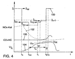
- FIG. 3 shows - this time during regeneration according to a first typical embodiment of the method according to the invention.
- the signal U ⁇ of the measuring device 20 (graph 104) is first measured and recorded in a known manner.
- the control unit 24 begins at a time t AH with a projection of the signal U ⁇ .
- the control unit 24 further calculates a period .DELTA.t, which corresponds to the current exhaust gas running time, which requires the exhaust gas until reaching the storage catalytic converter.
- the time of the actual regeneration end t E is then determined by subtracting the exhaust gas flow time ⁇ t from the time t S.
- the projection and thus the regeneration end t E is constantly updated on the basis of current operating parameters and on the basis of the actual signal profile U ⁇ .
- the projected sensor signal U ⁇ a second, not shown for reasons of clarity signal threshold U S2 , which is located between U S1 and U SE .
- the achievement of the signal threshold value U S2 signals that the NO x charge of the storage catalytic converter 18 is almost exhausted.
- the combustion lambda is further raised to a value of ⁇ F4 near 1. ⁇ F4 is then typically 0.95 to 0.98.
- the time t S determined at which the predetermined signal threshold U SE is achieved theoretically.
- the time of the (actual) regeneration end t E is then determined.
- the internal combustion engine 10 is switched back to the lean operating mode with ⁇ M in order to prevent pollutant breakdown (graph 106).
- the small amount of NO X (graph 102) still present in the storage catalytic converter 18 at this point in time ensures that the small amount of reducing agent still contained in the exhaust gas is largely converted.
Landscapes
- Engineering & Computer Science (AREA)
- Chemical & Material Sciences (AREA)
- Combustion & Propulsion (AREA)
- Mechanical Engineering (AREA)
- General Engineering & Computer Science (AREA)
- Chemical Kinetics & Catalysis (AREA)
- Exhaust Gas After Treatment (AREA)
Claims (21)
- Procédé pour la régénération des NOx d'un catalyseur accumulateur de NOx (18) disposé dans un canal de gaz d'échappement d'un moteur à combustion interne (10) pouvant fonctionner en régime pauvre, dans lequel le catalyseur accumulateur de NOx (18) est alimenté avec une atmosphère de gaz d'échappement riche à stoechiométrique avec λ ≤ 1 jusqu'à ce qu'il atteigne une fin de la régénération, et un déroulement de la régénération est suivi à l'aide d'un signal dépendant de l'oxygène produit par un dispositif de mesure sensible à l'oxygène (20) disposé en aval du catalyseur accumulateur de NOx (18), caractérisé en ce que(a) pendant la régénération des NOx, on fait un calcul de projection du signal dépendant de l'oxygène (Uλ) du dispositif de mesure (20),(b) variation d'un mélange air-carburant fourni au moteur à combustion interne (10) pendant la régénération (lambda de combustion) en fonction du signal calculé (Uλ) en tenant compte d'un intervalle de temps (Δt) correspondant essentiellement au temps de parcours des gaz d'échappement entre le moteur à combustion interne (10) et le catalyseur accumulateur de NOx (18), et(c) détermination d'un instant théorique (ts), auquel une valeur de seuil du signal (USE) prédéfinie est dépassée, sur la base du signal calculé (Uλ) et constatation de la fin de la régénération (tE) par soustraction de l'intervalle de temps (Δt) de l'instant théorique (ts) .
- Procédé selon la revendication 1, caractérisé en ce que l'on fait varier le mélange air-carburant (lambda de combustion) fourni au moteur à combustion interne (10) pendant la régénération en fonction du signal calculé (Uλ) et de l'instant (ts) en tenant compte de l'intervalle de temps (Δt).
- Procédé selon l'une quelconque des revendications précédentes, caractérisé en ce que l'on fait le calcul de projection du signal dépendant de l'oxygène (Uλ) à l'aide des paramètres de fonctionnement actuels du moteur à combustion interne (10) et/ou de l'installation des gaz d'échappement (12).
- Procédé selon la revendication 3, caractérisé en ce que l'on fait le calcul de projection du signal dépendant de l'oxygène (Uλ) en fonction d'un mélange air-carburant fourni au moteur à combustion interne (10) et/ou d'un débit massique de gaz d'échappement et/ou d'une température des gaz d'échappement et/ou d'une température du catalyseur.
- Procédé selon la revendication 3 ou 4, caractérisé en ce que l'on fait le calcul de projection du le signal dépendant de l'oxygène (Uλ) en tenant compte d'un modèle de comportement du catalyseur accumulateur de NOx (18).
- Procédé selon l'une quelconque des revendications 3 à 5, caractérisé en ce que l'on fait le calcul de projection du signal dépendant de l'oxygène (Uλ) en tenant compte d'un modèle de comportement du dispositif de mesure sensible à l'oxygène (20), en particulier d'une inertie du dispositif de mesure (20).
- Procédé selon l'une quelconque des revendications précédentes, caractérisé en ce que l'on commence le calcule de projection après l'expiration d'un temps prédéfini après le début de la régénération et/ou après le passage d'une masse prédéfinie de gaz d'échappement et/ou après le dépassement d'un seuil prédéfini du signal (Uλ).
- Procédé selon l'une quelconque des revendications précédentes, caractérisé en ce que l'on calcule le temps de parcours des gaz d'échappement (Δt) à l'aide des paramètres de fonctionnement actuels du moteur à combustion interne (10) ou on prédéfinit lequel.
- Procédé selon l'une quelconque des revendications précédentes, caractérisé en ce que l'on suspend le calcule de projection du signal (Uλ) lorsque des valeurs limites prédéfinies pour les conditions de fonctionnement du moteur à combustion interne (10) et/ou de l'installation des gaz d'échappement (12) ne sont pas respectées.
- Procédé selon la revendication 9, caractérisé en ce que l'on prédéfinit des valeurs limites pour le débit massique des gaz d'échappement et/ou pour la température du catalyseur accumulateur de NOx (18).
- Procédé selon la revendication 9 ou 10, caractérisé en ce que l'on suspend le calcule de projection du signal (Uλ) lors d'une interruption de la poussée pendant la régénération des NOx.
- Procédé selon l'une quelconque des revendications précédentes, caractérisé en ce que l'on relève le lambda de la combustion lorsque le signal de capteur calculé (Uλ) atteint une deuxième valeur de seuil de signal prédéfinie (US2) en tenant compte du temps de parcours des gaz d'échappement (Δt) ou après l'expiration d'une partie prédéfinie d'une durée de régénération déterminée par le calcule de projection.
- Procédé selon la revendication 12, caractérisé en ce que l'on relève le lambda de la combustion du moteur à combustion interne (10) avant la fin de la régénération (tE) à une valeur (λF4) qui est supérieure à une valeur précédente du lambda de la combustion et qui est ≤ 1.
- Procédé selon la revendication 13, caractérisé en ce que l'on relève le lambda de la combustion à λF4 = 0,94 à 0,99, en particulier à 0,95 à 0,98.
- Procédé selon l'une quelconque des revendications précédentes, caractérisé en ce que l'on abaisse le lambda de la combustion du moteur à combustion interne (10) à une valeur (λF2) inférieure à une valeur de lambda précédentes (λF1) jusqu'à ce que le signal de capteur calculé (Uλ) atteigne une troisième valeur de seuil de signal (US1) prédéfinie en tenant compte du temps de parcours des gaz d'échappement (Δt).
- Procédé selon la revendication 15, caractérisé en ce que l'on abaisse le lambda de la combustion à λF2 = 0,6 à 0,9, en particulier à 0,7 à 0,8.
- Procédé selon l'une quelconque des revendications précédentes, caractérisé en ce que l'on exécute la hausse et/ou la baisse du lambda de la combustion par étapes.
- Dispositif pour effectuer une régénération d'un catalyseur accumulateur de NOx (18) disposé dans un canal de gaz d'échappement d'un moteur à combustion interne (10) pouvant fonctionner en régime pauvre, dans lequel le catalyseur accumulateur de NOx (18) est alimenté avec une atmosphère de gaz d'échappement riche à stoechiométrique avec λ ≤ 1 jusqu'à ce qu'il atteigne une fin de la régénération, et un déroulement de la régénération est suivi à l'aide d'un signal dépendant de l'oxygène produit par un dispositif de mesure sensible à l'oxygène (20) disposé en aval du catalyseur accumulateur de NOx (18), caractérisé par des moyens permettant d'exécuter les étapes de procédé(a) faire un calcul de projection du signal dépendant de l'oxygène (Uλ) du dispositif de mesure (20) pendant la régénération des NOx,
et au moins une des mesures suivantes:(b) variation d'un mélange air-carburant fourni au moteur à combustion interne (10) pendant la régénération (lambda de combustion) en fonction du signal calculé (Uλ) en tenant compte d'un intervalle de temps (Δt) correspondant essentiellement au temps de parcours des gaz d'échappement entre le moteur à combustion interne (10) et le catalyseur accumulateur de NOx (18), et(c) détermination d'un instant théorique (ts), auquel une valeur de seuil du signal (USE) prédéfinie est dépassée, sur la base du signal calculé (Uλ) et constatation de la fin de la régénération (tE) par soustraction de l'intervalle de temps (Δt) de l'instant théorique (ts). - Dispositif selon la revendication 18, caractérisé en ce que les moyens comprennent une unité de commande (24), qui contient un algorithme pour commander les étapes du procédé sous une forme numérique.
- Dispositif selon la revendication 19, caractérisé en ce que l'unité de commande (24) est intégrée dans un appareil de commande du moteur (22).
- Dispositif selon l'une quelconque des revendications 18 à 20, caractérisé en ce que le dispositif de mesure sensible à l'oxygène (20) comprend une sonde lambda à large bande ou à réponse transitoire ou un détecteur de NOx.
Applications Claiming Priority (4)
| Application Number | Priority Date | Filing Date | Title |
|---|---|---|---|
| DE10057936 | 2000-11-22 | ||
| DE2000157938 DE10057938A1 (de) | 2000-11-22 | 2000-11-22 | Verfahren und Vorrichtung zur Regeneration eines NOx-Speicherkatalysators |
| DE2000157936 DE10057936A1 (de) | 2000-11-22 | 2000-11-22 | Verfahren und Vorrichtung zur Regeneration eines NOx-Speicherkatalysators |
| DE10057938 | 2000-11-22 |
Publications (4)
| Publication Number | Publication Date |
|---|---|
| EP1209332A2 EP1209332A2 (fr) | 2002-05-29 |
| EP1209332A3 EP1209332A3 (fr) | 2004-06-09 |
| EP1209332B1 true EP1209332B1 (fr) | 2008-06-25 |
| EP1209332B8 EP1209332B8 (fr) | 2008-08-13 |
Family
ID=26007746
Family Applications (1)
| Application Number | Title | Priority Date | Filing Date |
|---|---|---|---|
| EP20010250407 Expired - Lifetime EP1209332B8 (fr) | 2000-11-22 | 2001-11-21 | Méthode et appareil de régénération d'un catalyseur accumulateur de NOx |
Country Status (2)
| Country | Link |
|---|---|
| EP (1) | EP1209332B8 (fr) |
| DE (1) | DE50114044D1 (fr) |
Families Citing this family (6)
| Publication number | Priority date | Publication date | Assignee | Title |
|---|---|---|---|---|
| DE10361286B4 (de) | 2003-12-24 | 2013-09-19 | Daimler Ag | Verfahren zur Regeneration eines Stickoxid-Speicherkatalysators |
| GB2424197B (en) * | 2005-03-15 | 2009-01-14 | Ford Global Tech Llc | A method for adaptively controlling the regeneration of a lean nox trap |
| US8006480B2 (en) * | 2007-07-25 | 2011-08-30 | Eaton Corporation | Physical based LNT regeneration strategy |
| GB2504975A (en) * | 2012-08-15 | 2014-02-19 | Gm Global Tech Operations Inc | Method of controlling a DeSOx regeneration process of a Lean NOx Trap |
| FR3030620B1 (fr) * | 2014-12-22 | 2018-03-09 | Renault S.A.S | Procede de purge d'un piege a oxydes d'azote et dispositif de motorisation associe |
| US9631565B2 (en) * | 2015-09-15 | 2017-04-25 | Hyundai Motor Company | Control method for improving nitrogen oxide purification performance |
Family Cites Families (6)
| Publication number | Priority date | Publication date | Assignee | Title |
|---|---|---|---|---|
| JPH0814031A (ja) * | 1994-06-24 | 1996-01-16 | Hitachi Ltd | 内燃機関におけるno▲x▼還元触媒の還元・吸着性能の判定とno▲x▼低減方法 |
| DE59800195D1 (de) * | 1998-01-09 | 2000-08-17 | Ford Global Tech Inc | Verfahren zur Regeneration einer Stickoxidfalle im Abgassystem eines Verbrennungsmotors |
| DE19808382A1 (de) * | 1998-02-27 | 1999-09-02 | Volkswagen Ag | Steuerung eines NOx-Absorber-Katalysator |
| DE19844082C1 (de) * | 1998-09-25 | 1999-10-14 | Siemens Ag | Verfahren zum Regenerieren eines NOx-Speicherkatalysators |
| FR2785331B1 (fr) * | 1998-10-28 | 2000-12-22 | Renault | Procede de commande de la purge en oxydes d'azote d'un pot catalytique de traitement des gaz d'echappement d'un moteur a combustion interne |
| DE19915793A1 (de) * | 1999-04-08 | 2000-10-19 | Daimler Chrysler Ag | Verfahren zur Desorption eines Stickoxidadsorbers einer Abgasreinigungsanlage |
-
2001
- 2001-11-21 EP EP20010250407 patent/EP1209332B8/fr not_active Expired - Lifetime
- 2001-11-21 DE DE50114044T patent/DE50114044D1/de not_active Expired - Lifetime
Also Published As
| Publication number | Publication date |
|---|---|
| EP1209332A2 (fr) | 2002-05-29 |
| EP1209332B8 (fr) | 2008-08-13 |
| EP1209332A3 (fr) | 2004-06-09 |
| DE50114044D1 (de) | 2008-08-07 |
Similar Documents
| Publication | Publication Date | Title |
|---|---|---|
| EP1250524B1 (fr) | PROCEDE DE DESULFURATION D'UN CATALYSEUR ACCUMULATEUR DE NOx MONTE DANS LE CANAL POUR GAZ D'ECHAPPEMENT D'UN MOTEUR A COMBUSTION INTERNE | |
| DE19711295B4 (de) | Vorrichtung zur Ermittlung einer Verschlechterung eines Katalysators zur Abgasreinigung | |
| DE10226187B4 (de) | Verfahren und Vorrichtung zur Quantifizierung von in einer Emissionsbegrenzungseinrichtung gespeichertem Sauerstoff | |
| DE102006000537B4 (de) | Abgasreinigungssystem für eine Brennkraftmaschine | |
| DE60127013T2 (de) | Steuerung zur Verbesserung des Verhaltens eines Fahrzeuges | |
| DE19843879A1 (de) | Betrieb eines Verbrennungsmotors in Verbindung mit einem NOx-Speicherkatalysator und einem NOx-Sensor | |
| EP1366278B1 (fr) | PROCEDE DE régulation de la température d'un catalysateur | |
| EP1272744B1 (fr) | DISPOSITIF ET PROCEDE POUR DETERMINER LA NECESSITE DE REGENERATION D'UN CATALYSEUR ACCUMULATEUR DE NOx | |
| WO2005083250A1 (fr) | Procede permettant de determiner la charge effective en oxygene d'un catalyseur a trois voies d'un moteur a combustion interne a regulation lambda | |
| EP1329627B1 (fr) | Procédé et dispositif de contrôle d'une fonction de protection de composants | |
| DE10361286B4 (de) | Verfahren zur Regeneration eines Stickoxid-Speicherkatalysators | |
| EP1209332B1 (fr) | Méthode et appareil de régénération d'un catalyseur accumulateur de NOx | |
| EP1203144B1 (fr) | Procede de reglage d'un mode de travail d'un moteur a combustion interne | |
| EP2253821B1 (fr) | Procédé de nettoyage des gaz d'échappement d'un moteur à combustion interne doté d'un catalyseur | |
| DE10057938A1 (de) | Verfahren und Vorrichtung zur Regeneration eines NOx-Speicherkatalysators | |
| DE102004058680B4 (de) | Speicherkatalysator-Regenerationsverfahren und- Steuergerät | |
| DE10123148B4 (de) | Verfahren und Vorrichtung zur Entschwefelung eines Vorkatalysators | |
| DE10023079B4 (de) | Vorrichtung und Verfahren zur Steuerung einer NOx-Regeneration eines im Abgasstrang einer Verbrennungskraftmaschine angeordneten NOx-Speicherkatalysators | |
| EP1160425B1 (fr) | Méthode et procédé pour la régénération d'un catalyseur à stockage de NOx | |
| EP1365131B1 (fr) | Procédé de reglage d'un catalyseur d'accumulation de NOx | |
| DE10307457A1 (de) | Verfahren zum Betreiben eines Stickoxid-Speicherkatalysators einer Brennkraftmaschine | |
| DE10202935A1 (de) | Verfahren und Vorrichtung zur Entschwefelung eines Vorkatalysators | |
| DE10057936A1 (de) | Verfahren und Vorrichtung zur Regeneration eines NOx-Speicherkatalysators | |
| DE102004060125B4 (de) | Verfahren zur Steuerung der Be- und Entladung des Sauerstoffspeichers eines Abgaskatalysators | |
| DE10036390B4 (de) | Verfahren und Vorrichtung zur Entschwefelung eines NOx-Speicherkatalysators |
Legal Events
| Date | Code | Title | Description |
|---|---|---|---|
| PUAI | Public reference made under article 153(3) epc to a published international application that has entered the european phase |
Free format text: ORIGINAL CODE: 0009012 |
|
| AK | Designated contracting states |
Kind code of ref document: A2 Designated state(s): AT BE CH CY DE DK ES FI FR GB GR IE IT LI LU MC NL PT SE TR |
|
| AX | Request for extension of the european patent |
Free format text: AL;LT;LV;MK;RO;SI |
|
| RIC1 | Information provided on ipc code assigned before grant |
Ipc: 7F 02D 41/14 B Ipc: 7F 01N 3/08 B Ipc: 7F 02D 41/02 A |
|
| PUAL | Search report despatched |
Free format text: ORIGINAL CODE: 0009013 |
|
| AK | Designated contracting states |
Kind code of ref document: A3 Designated state(s): AT BE CH CY DE DK ES FI FR GB GR IE IT LI LU MC NL PT SE TR |
|
| AX | Request for extension of the european patent |
Extension state: AL LT LV MK RO SI |
|
| 17P | Request for examination filed |
Effective date: 20041209 |
|
| AKX | Designation fees paid |
Designated state(s): DE ES FR GB IT |
|
| 17Q | First examination report despatched |
Effective date: 20050318 |
|
| GRAP | Despatch of communication of intention to grant a patent |
Free format text: ORIGINAL CODE: EPIDOSNIGR1 |
|
| GRAS | Grant fee paid |
Free format text: ORIGINAL CODE: EPIDOSNIGR3 |
|
| GRAA | (expected) grant |
Free format text: ORIGINAL CODE: 0009210 |
|
| AK | Designated contracting states |
Kind code of ref document: B1 Designated state(s): DE ES FR GB IT |
|
| REG | Reference to a national code |
Ref country code: GB Ref legal event code: FG4D Free format text: NOT ENGLISH |
|
| RTI1 | Title (correction) |
Free format text: METHOD AND DEVICE FOR REGENERATING A NOX CATALYTIC CONVERTER |
|
| RTI2 | Title (correction) |
Free format text: METHOD AND DEVICE FOR REGENERATING AN NOX STORAGE CATALYTIC CONVERTER |
|
| REF | Corresponds to: |
Ref document number: 50114044 Country of ref document: DE Date of ref document: 20080807 Kind code of ref document: P |
|
| PG25 | Lapsed in a contracting state [announced via postgrant information from national office to epo] |
Ref country code: ES Free format text: LAPSE BECAUSE OF FAILURE TO SUBMIT A TRANSLATION OF THE DESCRIPTION OR TO PAY THE FEE WITHIN THE PRESCRIBED TIME-LIMIT Effective date: 20081006 |
|
| PLBE | No opposition filed within time limit |
Free format text: ORIGINAL CODE: 0009261 |
|
| STAA | Information on the status of an ep patent application or granted ep patent |
Free format text: STATUS: NO OPPOSITION FILED WITHIN TIME LIMIT |
|
| 26N | No opposition filed |
Effective date: 20090326 |
|
| GBPC | Gb: european patent ceased through non-payment of renewal fee |
Effective date: 20081121 |
|
| PG25 | Lapsed in a contracting state [announced via postgrant information from national office to epo] |
Ref country code: IT Free format text: LAPSE BECAUSE OF FAILURE TO SUBMIT A TRANSLATION OF THE DESCRIPTION OR TO PAY THE FEE WITHIN THE PRESCRIBED TIME-LIMIT Effective date: 20080625 |
|
| REG | Reference to a national code |
Ref country code: FR Ref legal event code: ST Effective date: 20090731 |
|
| PG25 | Lapsed in a contracting state [announced via postgrant information from national office to epo] |
Ref country code: GB Free format text: LAPSE BECAUSE OF NON-PAYMENT OF DUE FEES Effective date: 20081121 |
|
| REG | Reference to a national code |
Ref country code: DE Ref legal event code: R084 Ref document number: 50114044 Country of ref document: DE |
|
| PG25 | Lapsed in a contracting state [announced via postgrant information from national office to epo] |
Ref country code: FR Free format text: LAPSE BECAUSE OF NON-PAYMENT OF DUE FEES Effective date: 20081130 |
|
| REG | Reference to a national code |
Ref country code: DE Ref legal event code: R084 Ref document number: 50114044 Country of ref document: DE Effective date: 20110716 |
|
| PGFP | Annual fee paid to national office [announced via postgrant information from national office to epo] |
Ref country code: DE Payment date: 20151130 Year of fee payment: 15 |
|
| REG | Reference to a national code |
Ref country code: DE Ref legal event code: R119 Ref document number: 50114044 Country of ref document: DE |
|
| PG25 | Lapsed in a contracting state [announced via postgrant information from national office to epo] |
Ref country code: DE Free format text: LAPSE BECAUSE OF NON-PAYMENT OF DUE FEES Effective date: 20170601 |