EP1248675B1 - Katalytischer reaktor - Google Patents
Katalytischer reaktor Download PDFInfo
- Publication number
- EP1248675B1 EP1248675B1 EP01900200A EP01900200A EP1248675B1 EP 1248675 B1 EP1248675 B1 EP 1248675B1 EP 01900200 A EP01900200 A EP 01900200A EP 01900200 A EP01900200 A EP 01900200A EP 1248675 B1 EP1248675 B1 EP 1248675B1
- Authority
- EP
- European Patent Office
- Prior art keywords
- gas flow
- flow channels
- gas
- catalytic reactor
- reactor
- Prior art date
- Legal status (The legal status is an assumption and is not a legal conclusion. Google has not performed a legal analysis and makes no representation as to the accuracy of the status listed.)
- Expired - Lifetime
Links
Images


Classifications
-
- B—PERFORMING OPERATIONS; TRANSPORTING
- B01—PHYSICAL OR CHEMICAL PROCESSES OR APPARATUS IN GENERAL
- B01J—CHEMICAL OR PHYSICAL PROCESSES, e.g. CATALYSIS OR COLLOID CHEMISTRY; THEIR RELEVANT APPARATUS
- B01J19/00—Chemical, physical or physico-chemical processes in general; Their relevant apparatus
- B01J19/32—Packing elements in the form of grids or built-up elements for forming a unit or module inside the apparatus for mass or heat transfer
-
- B—PERFORMING OPERATIONS; TRANSPORTING
- B01—PHYSICAL OR CHEMICAL PROCESSES OR APPARATUS IN GENERAL
- B01J—CHEMICAL OR PHYSICAL PROCESSES, e.g. CATALYSIS OR COLLOID CHEMISTRY; THEIR RELEVANT APPARATUS
- B01J19/00—Chemical, physical or physico-chemical processes in general; Their relevant apparatus
- B01J19/24—Stationary reactors without moving elements inside
- B01J19/248—Reactors comprising multiple separated flow channels
- B01J19/249—Plate-type reactors
-
- B—PERFORMING OPERATIONS; TRANSPORTING
- B01—PHYSICAL OR CHEMICAL PROCESSES OR APPARATUS IN GENERAL
- B01J—CHEMICAL OR PHYSICAL PROCESSES, e.g. CATALYSIS OR COLLOID CHEMISTRY; THEIR RELEVANT APPARATUS
- B01J8/00—Chemical or physical processes in general, conducted in the presence of fluids and solid particles; Apparatus for such processes
- B01J8/02—Chemical or physical processes in general, conducted in the presence of fluids and solid particles; Apparatus for such processes with stationary particles, e.g. in fixed beds
- B01J8/0207—Chemical or physical processes in general, conducted in the presence of fluids and solid particles; Apparatus for such processes with stationary particles, e.g. in fixed beds the fluid flow within the bed being predominantly horizontal
- B01J8/0214—Chemical or physical processes in general, conducted in the presence of fluids and solid particles; Apparatus for such processes with stationary particles, e.g. in fixed beds the fluid flow within the bed being predominantly horizontal in a cylindrical annular shaped bed
-
- B—PERFORMING OPERATIONS; TRANSPORTING
- B01—PHYSICAL OR CHEMICAL PROCESSES OR APPARATUS IN GENERAL
- B01J—CHEMICAL OR PHYSICAL PROCESSES, e.g. CATALYSIS OR COLLOID CHEMISTRY; THEIR RELEVANT APPARATUS
- B01J8/00—Chemical or physical processes in general, conducted in the presence of fluids and solid particles; Apparatus for such processes
- B01J8/02—Chemical or physical processes in general, conducted in the presence of fluids and solid particles; Apparatus for such processes with stationary particles, e.g. in fixed beds
- B01J8/06—Chemical or physical processes in general, conducted in the presence of fluids and solid particles; Apparatus for such processes with stationary particles, e.g. in fixed beds in tube reactors; the solid particles being arranged in tubes
- B01J8/067—Heating or cooling the reactor
-
- C—CHEMISTRY; METALLURGY
- C01—INORGANIC CHEMISTRY
- C01B—NON-METALLIC ELEMENTS; COMPOUNDS THEREOF; METALLOIDS OR COMPOUNDS THEREOF NOT COVERED BY SUBCLASS C01C
- C01B3/00—Hydrogen; Gaseous mixtures containing hydrogen; Separation of hydrogen from mixtures containing it; Purification of hydrogen; Reversible storage of hydrogen
- C01B3/02—Production of hydrogen; Production of gaseous mixtures containing hydrogen
- C01B3/32—Production of hydrogen; Production of gaseous mixtures containing hydrogen by reaction of gaseous or liquid organic compounds with gasifying agents, e.g. water, carbon dioxide or air
- C01B3/34—Production of hydrogen; Production of gaseous mixtures containing hydrogen by reaction of gaseous or liquid organic compounds with gasifying agents, e.g. water, carbon dioxide or air by reaction of hydrocarbons with gasifying agents
- C01B3/38—Production of hydrogen; Production of gaseous mixtures containing hydrogen by reaction of gaseous or liquid organic compounds with gasifying agents, e.g. water, carbon dioxide or air by reaction of hydrocarbons with gasifying agents using catalysts
- C01B3/384—Production of hydrogen; Production of gaseous mixtures containing hydrogen by reaction of gaseous or liquid organic compounds with gasifying agents, e.g. water, carbon dioxide or air by reaction of hydrocarbons with gasifying agents using catalysts with external heating of the catalyst
-
- C—CHEMISTRY; METALLURGY
- C07—ORGANIC CHEMISTRY
- C07C—ACYCLIC OR CARBOCYCLIC COMPOUNDS
- C07C2/00—Preparation of hydrocarbons from hydrocarbons containing a smaller number of carbon atoms
-
- B—PERFORMING OPERATIONS; TRANSPORTING
- B01—PHYSICAL OR CHEMICAL PROCESSES OR APPARATUS IN GENERAL
- B01J—CHEMICAL OR PHYSICAL PROCESSES, e.g. CATALYSIS OR COLLOID CHEMISTRY; THEIR RELEVANT APPARATUS
- B01J2208/00—Processes carried out in the presence of solid particles; Reactors therefor
- B01J2208/00008—Controlling the process
- B01J2208/00017—Controlling the temperature
- B01J2208/00106—Controlling the temperature by indirect heat exchange
- B01J2208/00309—Controlling the temperature by indirect heat exchange with two or more reactions in heat exchange with each other, such as an endothermic reaction in heat exchange with an exothermic reaction
-
- B—PERFORMING OPERATIONS; TRANSPORTING
- B01—PHYSICAL OR CHEMICAL PROCESSES OR APPARATUS IN GENERAL
- B01J—CHEMICAL OR PHYSICAL PROCESSES, e.g. CATALYSIS OR COLLOID CHEMISTRY; THEIR RELEVANT APPARATUS
- B01J2208/00—Processes carried out in the presence of solid particles; Reactors therefor
- B01J2208/00008—Controlling the process
- B01J2208/00017—Controlling the temperature
- B01J2208/00389—Controlling the temperature using electric heating or cooling elements
- B01J2208/00398—Controlling the temperature using electric heating or cooling elements inside the reactor bed
-
- B—PERFORMING OPERATIONS; TRANSPORTING
- B01—PHYSICAL OR CHEMICAL PROCESSES OR APPARATUS IN GENERAL
- B01J—CHEMICAL OR PHYSICAL PROCESSES, e.g. CATALYSIS OR COLLOID CHEMISTRY; THEIR RELEVANT APPARATUS
- B01J2208/00—Processes carried out in the presence of solid particles; Reactors therefor
- B01J2208/00008—Controlling the process
- B01J2208/00017—Controlling the temperature
- B01J2208/00389—Controlling the temperature using electric heating or cooling elements
- B01J2208/00415—Controlling the temperature using electric heating or cooling elements electric resistance heaters
-
- B—PERFORMING OPERATIONS; TRANSPORTING
- B01—PHYSICAL OR CHEMICAL PROCESSES OR APPARATUS IN GENERAL
- B01J—CHEMICAL OR PHYSICAL PROCESSES, e.g. CATALYSIS OR COLLOID CHEMISTRY; THEIR RELEVANT APPARATUS
- B01J2219/00—Chemical, physical or physico-chemical processes in general; Their relevant apparatus
- B01J2219/00049—Controlling or regulating processes
- B01J2219/00051—Controlling the temperature
- B01J2219/00074—Controlling the temperature by indirect heating or cooling employing heat exchange fluids
- B01J2219/00117—Controlling the temperature by indirect heating or cooling employing heat exchange fluids with two or more reactions in heat exchange with each other, such as an endothermic reaction in heat exchange with an exothermic reaction
-
- B—PERFORMING OPERATIONS; TRANSPORTING
- B01—PHYSICAL OR CHEMICAL PROCESSES OR APPARATUS IN GENERAL
- B01J—CHEMICAL OR PHYSICAL PROCESSES, e.g. CATALYSIS OR COLLOID CHEMISTRY; THEIR RELEVANT APPARATUS
- B01J2219/00—Chemical, physical or physico-chemical processes in general; Their relevant apparatus
- B01J2219/24—Stationary reactors without moving elements inside
- B01J2219/2401—Reactors comprising multiple separate flow channels
- B01J2219/245—Plate-type reactors
- B01J2219/2451—Geometry of the reactor
- B01J2219/2453—Plates arranged in parallel
-
- B—PERFORMING OPERATIONS; TRANSPORTING
- B01—PHYSICAL OR CHEMICAL PROCESSES OR APPARATUS IN GENERAL
- B01J—CHEMICAL OR PHYSICAL PROCESSES, e.g. CATALYSIS OR COLLOID CHEMISTRY; THEIR RELEVANT APPARATUS
- B01J2219/00—Chemical, physical or physico-chemical processes in general; Their relevant apparatus
- B01J2219/24—Stationary reactors without moving elements inside
- B01J2219/2401—Reactors comprising multiple separate flow channels
- B01J2219/245—Plate-type reactors
- B01J2219/2451—Geometry of the reactor
- B01J2219/2456—Geometry of the plates
- B01J2219/2458—Flat plates, i.e. plates which are not corrugated or otherwise structured, e.g. plates with cylindrical shape
-
- B—PERFORMING OPERATIONS; TRANSPORTING
- B01—PHYSICAL OR CHEMICAL PROCESSES OR APPARATUS IN GENERAL
- B01J—CHEMICAL OR PHYSICAL PROCESSES, e.g. CATALYSIS OR COLLOID CHEMISTRY; THEIR RELEVANT APPARATUS
- B01J2219/00—Chemical, physical or physico-chemical processes in general; Their relevant apparatus
- B01J2219/24—Stationary reactors without moving elements inside
- B01J2219/2401—Reactors comprising multiple separate flow channels
- B01J2219/245—Plate-type reactors
- B01J2219/2451—Geometry of the reactor
- B01J2219/2456—Geometry of the plates
- B01J2219/2459—Corrugated plates
-
- B—PERFORMING OPERATIONS; TRANSPORTING
- B01—PHYSICAL OR CHEMICAL PROCESSES OR APPARATUS IN GENERAL
- B01J—CHEMICAL OR PHYSICAL PROCESSES, e.g. CATALYSIS OR COLLOID CHEMISTRY; THEIR RELEVANT APPARATUS
- B01J2219/00—Chemical, physical or physico-chemical processes in general; Their relevant apparatus
- B01J2219/24—Stationary reactors without moving elements inside
- B01J2219/2401—Reactors comprising multiple separate flow channels
- B01J2219/245—Plate-type reactors
- B01J2219/2461—Heat exchange aspects
- B01J2219/2465—Two reactions in indirect heat exchange with each other
-
- B—PERFORMING OPERATIONS; TRANSPORTING
- B01—PHYSICAL OR CHEMICAL PROCESSES OR APPARATUS IN GENERAL
- B01J—CHEMICAL OR PHYSICAL PROCESSES, e.g. CATALYSIS OR COLLOID CHEMISTRY; THEIR RELEVANT APPARATUS
- B01J2219/00—Chemical, physical or physico-chemical processes in general; Their relevant apparatus
- B01J2219/24—Stationary reactors without moving elements inside
- B01J2219/2401—Reactors comprising multiple separate flow channels
- B01J2219/245—Plate-type reactors
- B01J2219/2461—Heat exchange aspects
- B01J2219/2467—Additional heat exchange means, e.g. electric resistance heaters, coils
-
- B—PERFORMING OPERATIONS; TRANSPORTING
- B01—PHYSICAL OR CHEMICAL PROCESSES OR APPARATUS IN GENERAL
- B01J—CHEMICAL OR PHYSICAL PROCESSES, e.g. CATALYSIS OR COLLOID CHEMISTRY; THEIR RELEVANT APPARATUS
- B01J2219/00—Chemical, physical or physico-chemical processes in general; Their relevant apparatus
- B01J2219/24—Stationary reactors without moving elements inside
- B01J2219/2401—Reactors comprising multiple separate flow channels
- B01J2219/245—Plate-type reactors
- B01J2219/2476—Construction materials
- B01J2219/2477—Construction materials of the catalysts
- B01J2219/2479—Catalysts coated on the surface of plates or inserts
-
- B—PERFORMING OPERATIONS; TRANSPORTING
- B01—PHYSICAL OR CHEMICAL PROCESSES OR APPARATUS IN GENERAL
- B01J—CHEMICAL OR PHYSICAL PROCESSES, e.g. CATALYSIS OR COLLOID CHEMISTRY; THEIR RELEVANT APPARATUS
- B01J2219/00—Chemical, physical or physico-chemical processes in general; Their relevant apparatus
- B01J2219/24—Stationary reactors without moving elements inside
- B01J2219/2401—Reactors comprising multiple separate flow channels
- B01J2219/245—Plate-type reactors
- B01J2219/2476—Construction materials
- B01J2219/2477—Construction materials of the catalysts
- B01J2219/2482—Catalytically active foils; Plates having catalytically activity on their own
-
- B—PERFORMING OPERATIONS; TRANSPORTING
- B01—PHYSICAL OR CHEMICAL PROCESSES OR APPARATUS IN GENERAL
- B01J—CHEMICAL OR PHYSICAL PROCESSES, e.g. CATALYSIS OR COLLOID CHEMISTRY; THEIR RELEVANT APPARATUS
- B01J2219/00—Chemical, physical or physico-chemical processes in general; Their relevant apparatus
- B01J2219/24—Stationary reactors without moving elements inside
- B01J2219/2401—Reactors comprising multiple separate flow channels
- B01J2219/245—Plate-type reactors
- B01J2219/2476—Construction materials
- B01J2219/2483—Construction materials of the plates
- B01J2219/2485—Metals or alloys
- B01J2219/2486—Steel
-
- B—PERFORMING OPERATIONS; TRANSPORTING
- B01—PHYSICAL OR CHEMICAL PROCESSES OR APPARATUS IN GENERAL
- B01J—CHEMICAL OR PHYSICAL PROCESSES, e.g. CATALYSIS OR COLLOID CHEMISTRY; THEIR RELEVANT APPARATUS
- B01J2219/00—Chemical, physical or physico-chemical processes in general; Their relevant apparatus
- B01J2219/24—Stationary reactors without moving elements inside
- B01J2219/2401—Reactors comprising multiple separate flow channels
- B01J2219/245—Plate-type reactors
- B01J2219/2491—Other constructional details
- B01J2219/2492—Assembling means
- B01J2219/2493—Means for assembling plates together, e.g. sealing means, screws, bolts
-
- B—PERFORMING OPERATIONS; TRANSPORTING
- B01—PHYSICAL OR CHEMICAL PROCESSES OR APPARATUS IN GENERAL
- B01J—CHEMICAL OR PHYSICAL PROCESSES, e.g. CATALYSIS OR COLLOID CHEMISTRY; THEIR RELEVANT APPARATUS
- B01J2219/00—Chemical, physical or physico-chemical processes in general; Their relevant apparatus
- B01J2219/24—Stationary reactors without moving elements inside
- B01J2219/2401—Reactors comprising multiple separate flow channels
- B01J2219/245—Plate-type reactors
- B01J2219/2491—Other constructional details
- B01J2219/2492—Assembling means
- B01J2219/2496—Means for assembling modules together, e.g. casings, holders, fluidic connectors
-
- B—PERFORMING OPERATIONS; TRANSPORTING
- B01—PHYSICAL OR CHEMICAL PROCESSES OR APPARATUS IN GENERAL
- B01J—CHEMICAL OR PHYSICAL PROCESSES, e.g. CATALYSIS OR COLLOID CHEMISTRY; THEIR RELEVANT APPARATUS
- B01J2219/00—Chemical, physical or physico-chemical processes in general; Their relevant apparatus
- B01J2219/24—Stationary reactors without moving elements inside
- B01J2219/2401—Reactors comprising multiple separate flow channels
- B01J2219/245—Plate-type reactors
- B01J2219/2491—Other constructional details
- B01J2219/2497—Size aspects, i.e. concrete sizes are being mentioned in the classified document
-
- B—PERFORMING OPERATIONS; TRANSPORTING
- B01—PHYSICAL OR CHEMICAL PROCESSES OR APPARATUS IN GENERAL
- B01J—CHEMICAL OR PHYSICAL PROCESSES, e.g. CATALYSIS OR COLLOID CHEMISTRY; THEIR RELEVANT APPARATUS
- B01J2219/00—Chemical, physical or physico-chemical processes in general; Their relevant apparatus
- B01J2219/24—Stationary reactors without moving elements inside
- B01J2219/2401—Reactors comprising multiple separate flow channels
- B01J2219/245—Plate-type reactors
- B01J2219/2491—Other constructional details
- B01J2219/2498—Additional structures inserted in the channels, e.g. plates, catalyst holding meshes
-
- B—PERFORMING OPERATIONS; TRANSPORTING
- B01—PHYSICAL OR CHEMICAL PROCESSES OR APPARATUS IN GENERAL
- B01J—CHEMICAL OR PHYSICAL PROCESSES, e.g. CATALYSIS OR COLLOID CHEMISTRY; THEIR RELEVANT APPARATUS
- B01J2219/00—Chemical, physical or physico-chemical processes in general; Their relevant apparatus
- B01J2219/32—Details relating to packing elements in the form of grids or built-up elements for forming a unit of module inside the apparatus for mass or heat transfer
- B01J2219/322—Basic shape of the elements
- B01J2219/32203—Sheets
- B01J2219/32206—Flat sheets
-
- B—PERFORMING OPERATIONS; TRANSPORTING
- B01—PHYSICAL OR CHEMICAL PROCESSES OR APPARATUS IN GENERAL
- B01J—CHEMICAL OR PHYSICAL PROCESSES, e.g. CATALYSIS OR COLLOID CHEMISTRY; THEIR RELEVANT APPARATUS
- B01J2219/00—Chemical, physical or physico-chemical processes in general; Their relevant apparatus
- B01J2219/32—Details relating to packing elements in the form of grids or built-up elements for forming a unit of module inside the apparatus for mass or heat transfer
- B01J2219/322—Basic shape of the elements
- B01J2219/32203—Sheets
- B01J2219/3221—Corrugated sheets
-
- B—PERFORMING OPERATIONS; TRANSPORTING
- B01—PHYSICAL OR CHEMICAL PROCESSES OR APPARATUS IN GENERAL
- B01J—CHEMICAL OR PHYSICAL PROCESSES, e.g. CATALYSIS OR COLLOID CHEMISTRY; THEIR RELEVANT APPARATUS
- B01J2219/00—Chemical, physical or physico-chemical processes in general; Their relevant apparatus
- B01J2219/32—Details relating to packing elements in the form of grids or built-up elements for forming a unit of module inside the apparatus for mass or heat transfer
- B01J2219/322—Basic shape of the elements
- B01J2219/32203—Sheets
- B01J2219/32213—Plurality of essentially parallel sheets
-
- B—PERFORMING OPERATIONS; TRANSPORTING
- B01—PHYSICAL OR CHEMICAL PROCESSES OR APPARATUS IN GENERAL
- B01J—CHEMICAL OR PHYSICAL PROCESSES, e.g. CATALYSIS OR COLLOID CHEMISTRY; THEIR RELEVANT APPARATUS
- B01J2219/00—Chemical, physical or physico-chemical processes in general; Their relevant apparatus
- B01J2219/32—Details relating to packing elements in the form of grids or built-up elements for forming a unit of module inside the apparatus for mass or heat transfer
- B01J2219/324—Composition or microstructure of the elements
- B01J2219/32466—Composition or microstructure of the elements comprising catalytically active material
- B01J2219/32475—Composition or microstructure of the elements comprising catalytically active material involving heat exchange
-
- B—PERFORMING OPERATIONS; TRANSPORTING
- B01—PHYSICAL OR CHEMICAL PROCESSES OR APPARATUS IN GENERAL
- B01J—CHEMICAL OR PHYSICAL PROCESSES, e.g. CATALYSIS OR COLLOID CHEMISTRY; THEIR RELEVANT APPARATUS
- B01J23/00—Catalysts comprising metals or metal oxides or hydroxides, not provided for in group B01J21/00
- B01J23/38—Catalysts comprising metals or metal oxides or hydroxides, not provided for in group B01J21/00 of noble metals
- B01J23/40—Catalysts comprising metals or metal oxides or hydroxides, not provided for in group B01J21/00 of noble metals of the platinum group metals
- B01J23/46—Ruthenium, rhodium, osmium or iridium
- B01J23/464—Rhodium
-
- B—PERFORMING OPERATIONS; TRANSPORTING
- B01—PHYSICAL OR CHEMICAL PROCESSES OR APPARATUS IN GENERAL
- B01J—CHEMICAL OR PHYSICAL PROCESSES, e.g. CATALYSIS OR COLLOID CHEMISTRY; THEIR RELEVANT APPARATUS
- B01J37/00—Processes, in general, for preparing catalysts; Processes, in general, for activation of catalysts
- B01J37/0009—Use of binding agents; Moulding; Pressing; Powdering; Granulating; Addition of materials ameliorating the mechanical properties of the product catalyst
- B01J37/0027—Powdering
-
- B—PERFORMING OPERATIONS; TRANSPORTING
- B01—PHYSICAL OR CHEMICAL PROCESSES OR APPARATUS IN GENERAL
- B01J—CHEMICAL OR PHYSICAL PROCESSES, e.g. CATALYSIS OR COLLOID CHEMISTRY; THEIR RELEVANT APPARATUS
- B01J37/00—Processes, in general, for preparing catalysts; Processes, in general, for activation of catalysts
- B01J37/02—Impregnation, coating or precipitation
- B01J37/024—Multiple impregnation or coating
- B01J37/0242—Coating followed by impregnation
-
- C—CHEMISTRY; METALLURGY
- C01—INORGANIC CHEMISTRY
- C01B—NON-METALLIC ELEMENTS; COMPOUNDS THEREOF; METALLOIDS OR COMPOUNDS THEREOF NOT COVERED BY SUBCLASS C01C
- C01B2203/00—Integrated processes for the production of hydrogen or synthesis gas
- C01B2203/02—Processes for making hydrogen or synthesis gas
- C01B2203/0205—Processes for making hydrogen or synthesis gas containing a reforming step
- C01B2203/0227—Processes for making hydrogen or synthesis gas containing a reforming step containing a catalytic reforming step
- C01B2203/0233—Processes for making hydrogen or synthesis gas containing a reforming step containing a catalytic reforming step the reforming step being a steam reforming step
-
- C—CHEMISTRY; METALLURGY
- C01—INORGANIC CHEMISTRY
- C01B—NON-METALLIC ELEMENTS; COMPOUNDS THEREOF; METALLOIDS OR COMPOUNDS THEREOF NOT COVERED BY SUBCLASS C01C
- C01B2203/00—Integrated processes for the production of hydrogen or synthesis gas
- C01B2203/08—Methods of heating or cooling
- C01B2203/0805—Methods of heating the process for making hydrogen or synthesis gas
- C01B2203/0811—Methods of heating the process for making hydrogen or synthesis gas by combustion of fuel
-
- C—CHEMISTRY; METALLURGY
- C01—INORGANIC CHEMISTRY
- C01B—NON-METALLIC ELEMENTS; COMPOUNDS THEREOF; METALLOIDS OR COMPOUNDS THEREOF NOT COVERED BY SUBCLASS C01C
- C01B2203/00—Integrated processes for the production of hydrogen or synthesis gas
- C01B2203/08—Methods of heating or cooling
- C01B2203/0805—Methods of heating the process for making hydrogen or synthesis gas
- C01B2203/0838—Methods of heating the process for making hydrogen or synthesis gas by heat exchange with exothermic reactions, other than by combustion of fuel
- C01B2203/0844—Methods of heating the process for making hydrogen or synthesis gas by heat exchange with exothermic reactions, other than by combustion of fuel the non-combustive exothermic reaction being another reforming reaction as defined in groups C01B2203/02 - C01B2203/0294
-
- Y—GENERAL TAGGING OF NEW TECHNOLOGICAL DEVELOPMENTS; GENERAL TAGGING OF CROSS-SECTIONAL TECHNOLOGIES SPANNING OVER SEVERAL SECTIONS OF THE IPC; TECHNICAL SUBJECTS COVERED BY FORMER USPC CROSS-REFERENCE ART COLLECTIONS [XRACs] AND DIGESTS
- Y02—TECHNOLOGIES OR APPLICATIONS FOR MITIGATION OR ADAPTATION AGAINST CLIMATE CHANGE
- Y02P—CLIMATE CHANGE MITIGATION TECHNOLOGIES IN THE PRODUCTION OR PROCESSING OF GOODS
- Y02P20/00—Technologies relating to chemical industry
- Y02P20/50—Improvements relating to the production of bulk chemicals
- Y02P20/52—Improvements relating to the production of bulk chemicals using catalysts, e.g. selective catalysts
Definitions
- This invention relates to a catalytic reactor suitable for use in performing gas phase reactions at elevated pressures, and particularly but not exclusively for performing endothermic reactions, and also to a chemical process using the catalytic reactor.
- a catalyst comprising an aluminium-bearing ferritic alloy substrate, coated with a layer of a refractory oxide such as alumina, titania or zirconia, and then with a catalytic platinum-group metal.
- a catalyst body may comprise substantially flat sheets and corrugated sheets of such material arranged alternately so as to define channels through the body, either several such sheets arranged in a stack, or two such sheets wound together to form a coil. In these examples both the flat sheets and the corrugated sheets have small-scale corrugations superimposed upon them to help in the formation of the coating.
- Such catalyst bodies are described as being suitable for use in treating exhaust gas from vehicles.
- Such a reactor is referred to as a micro-reactor, and the grooves are referred to as micro-structures; for example the plates themselves are said to be of thickness between 0.3 and 0.5 mm, so that the grooves are of very small cross sectional area.
- EP 0 885 653 A (Friedrich et al.) describes an alternative type of catalytic reactor in which the channels are of larger cross-section, being defined by a single long sheet folded into a concertina or zigzag, so as to form many parallel flow paths, and with a corrugated foil placed in each flow path.
- the foils may be coated with suitable catalysts.
- the foils are removable.
- Such a reactor is not suitable for use with a significant pressure difference between adjacent flow channels, as any pressure difference must be withstood by the entire area of each flow channel; and because one side and both ends of each flow channel are open.
- US 6 098 396 DE 19 923 431 (Wen et al.) describes a catalytic reactor for use in combination with an internal combustion engine, consisting of several corrugated foils with different catalysts on the opposed surfaces, one catalyzing an exothermic reaction and the other an endothermic reaction; a fuel/air mixture flows over both surfaces. There is no pressure difference between the gases on opposite sides of each foil, as the same gas mixture is supplied to each side.
- a catalytic reactor comprising a plurality of metal sheets arranged to define first gas flow channels between adjacent sheets, means to define second gas flow channels in proximity to the first gas flow channels, arranged so as to ensure good thermal contact between gases in the first and the second gas flow channels, catalytic material on at least some surfaces within each flow channel, and headers to supply gas mixtures to the gas flow channels, the headers being arranged to supply different gas mixtures to the first and the second gas flow channels, the metal sheets being flat and the first and second gas flow channels being defined by grooves therein such that the gases in the first and the second gas flow channels may differ in pressure by several atmospheres, and the portions of the sheet between the grooves being in contact with the adjacent metal sheet and so providing thermal contact, and the metal sheets being bonded together as a stack, and characterized by corrugated foils provided in the gas flow channels, the foils being of an aluminium-bearing ferritic steel that forms an adherent oxide coating of alumina when heated in air, and having the cata
- the second gas flow channels are also defined between the metal sheets, first and second gas flow channels being defined alternately between successive such sheets.
- both the first and the second gas flow channels are preferably less than 5 mm wide in at least one direction transverse to the gas flow direction. More preferably both the first and the second gas flow channels are less than 2 mm wide in at least one such direction.
- the grooves may be machined across the surfaces of the sheets, the reactor comprising a stack of such flat plates, the grooves in adjacent plates following different paths.
- the grooves themselves might be for example 20 mm wide, each groove accommodating a corrugated sheet or foil of material coated with catalytic material. To ensure that the gas flow channels are gas tight the plates or sheets are bonded together.
- the gas mixture supplied to each gas flow channel is different from the gas mixture supplied to the adjacent channels, and the corresponding chemical reactions are also different.
- one of the reactions is endothermic while the other reaction is exothermic. In that case heat is transferred through the wall of the sheet separating the adjacent channels, from the exothermic reaction to the endothermic reaction.
- the sheets themselves are also coated with suitable catalytic material.
- This reactor is particularly suitable for performing methane/steam reforming (which is an endothermic reaction, generating hydrogen and carbon monoxide), and the alternate channels might contain a methane/air mixture so that the exothermic oxidation reaction provides the necessary heat for the endothermic reforming reaction.
- methane/steam reforming which is an endothermic reaction, generating hydrogen and carbon monoxide
- the alternate channels might contain a methane/air mixture so that the exothermic oxidation reaction provides the necessary heat for the endothermic reforming reaction.
- the oxidation reaction several different catalysts may be used, for example palladium or platinum on a ceramic support; for example platinum on a lanthanum-stabilised alumina support, or palladium on zirconia.
- the preferred catalyst for the oxidation reaction is platinum on stabilised alumina.
- the reforming reaction also several different catalysts may be used, for example nickel, platinum, palladium, ruthenium or rhodium, which may be used on ceramic coatings; the preferred catalyst for the reforming reaction is rhodium or platinum/rhodium on alumina.
- the oxidation reaction may be carried out at substantially atmospheric pressure, while the reforming reaction is preferably carried out at elevated pressure, for example up to 2 MPa (20 atmospheres), more typically 300 kPa or 500 kPa.
- the reactor may be made of a metal such as an aluminium-bearing ferritic steel, in particular of the type known as Fecralloy (trade mark) which is iron with up to 20% chromium, 0.5 - 12% aluminium, and 0.1 - 3% yttrium.
- Fecralloy trade mark
- it might comprise iron with 15% chromium, 4% aluminium, and 0.3% yttrium.
- this metal is heated in air it forms an adherent oxide coating of alumina which protects the alloy against further oxidation.
- this metal is used as a catalyst substrate, and is coated with a ceramic layer into which a catalyst material is incorporated, the alumina oxide layer on the metal is believed to bind with the oxide coating, so ensuring the catalytic material adheres to the metal substrate.
- the invention also provides a method of performing chemical reactions, with the features of claim 6; and a process for processing methane with the features of claim 9; in both cases such a reactor is used.
- a catalytic reactor 10 (which does not fall within the present invention) consists of several nested concentric pressure tubes 12 of Fecralloy steel, each of wall thickness 0.5 mm (only four are shown in the figure, but the number of tubes 12 might in practice be say fifteen or sixteen).
- the innermost tube 12 contains an electrical heating element 14.
- the annular channels 15 between the tubes 12 locate foils 16 of corrugated Fecralloy steel whose corrugations are typically 2.0 mm high (peak to peak) with a pitch of 2.0 mm.
- the surfaces of the first, third, fifth etc. annular channels 15a are coated with a zirconia sol, and the surfaces of the second, fourth, sixth etc. annular channels 15b are coated with an alumina sol.
- This may be performed by temporarily blocking the end of one set of annular channels, for example with wax, and immersing the assembly in the appropriate sol.
- the assembly is then dried slowly, and then sintered, for example in an air furnace, raising the temperature to for example 1100°C over a period of four hours and then holding it at that temperature for a further four hours.
- catalyst materials are then introduced for example in the form of a salt of the appropriate metal: palladium is introduced onto the zirconia coating in the channels 15a, and rhodium is introduced onto the alumina coating in the channels 15b in this example.
- the catalyst metals are then formed by a heat treatment to decompose (or reduce) the salt.
- Annular end caps 18 are then laser welded onto the ends of each annular channel 15, each end cap 18 communicating with an inlet or outlet duct 20.
- the external diameter of the resulting reactor 10 is 50 mm, and it is of length 500 mm.
- the reactor 10 is particularly suitable for performing steam/methane reforming, that is to say the reaction: H 2 O + CH 4 ⁇ CO + 3H 2
- This reaction is endothermic, and is catalysed by the rhodium catalyst in the channels 15b.
- the heat required to cause this reaction may be provided by combustion of methane, that is to say: CH 4 + 2O 2 ⁇ CO 2 + 2H 2 O which is an exothermic reaction, and is catalysed by the palladium catalyst in the channels 15a.
- the heat generated by this combustion reaction is conducted through the walls of the tubes 12 into the adjacent channels 15b.
- the reactor 10 is initially heated using the electrical heating element 14.
- a mixture of methane and air is then supplied to all the channels 15a at approximately atmospheric pressure, where it undergoes catalytic combustion.
- a mixture of steam and methane is supplied to the alternate channels 15b, where the steam/methane reforming reaction occurs; the steam and methane mixture is preferably at an elevated pressure, as this raises the mass flow rate and so enables a larger quantity of methane gas to be treated.
- these channels 15b may be at a pressure of 1 MPa.
- the gas mixture produced by the steam/methane reforming can then be used to perform a Fischer-Tropsch synthesis, that is to say: carbon monoxide + hydrogen ⁇ paraffin or olefin (say C 10 ) + water which is an exothermic reaction, occurring at an elevated temperature, for example 320°C, and an elevated pressure (e.g. 1.8-2.2 MPa) in the presence of a catalyst such as iron, cobalt or fused magnetite, with a potassium promoter.
- a catalyst such as iron, cobalt or fused magnetite
- the heat given out by this synthesis reaction may be used to provide at least part of the heat required by the steam/methane reforming reaction, for example a heat transfer fluid such as helium may be used to transfer the heat from a reactor in which the Fischer-Tropsch synthesis is occurring, the heat being used to preheat at least one of the streams of gases supplied to the reactor 10.
- a heat transfer fluid such as helium may be used to transfer the heat from a reactor in which the Fischer-Tropsch synthesis is occurring, the heat being used to preheat at least one of the streams of gases supplied to the reactor 10.
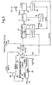
- the feed gas 24 consists primarily of methane, with a small percentage (say 10%) of ethane and propane at 10 bar. It is passed through a heat exchanger 25 so it is at about 400°C and is then supplied via a fluidic vortex mixer 26 to a first catalytic reactor 28; in the mixer 26 the feed gas is mixed with a stream of steam that is also at about 400°C and 10 bar, these streams entering the mixer 26 through tangential inlets and following a spiral path to an axial outlet so they become thoroughly mixed.
- the first part of the reactor 28 is a pre-reformer 29 with a nickel methanation catalyst at 400°C, in which the higher alkanes react with the steam to form methane (and carbon monoxide).
- the second part of the reactor 28 is a reformer 30 with a platinum/rhodium catalyst, in which the methane and steam react to form carbon monoxide and hydrogen. This reaction may be performed at 800°C, the heat being provided by combustion of methane over a palladium (or platinum) catalyst.
- the hot gases from the reformer 30 are then quenched by passing through a heat exchanger 31 to provide the hot steam that is supplied to the vortex mixer 26, and then through the heat exchanger 25 in which they lose heat to the feed gas.
- the stream of carbon monoxide and hydrogen is then supplied to a third reactor 32 in which the carbon monoxide and hydrogen react, undergoing Fischer-Tropsch synthesis to form a paraffin or similar compound.
- This reaction is exothermic, preferably taking place at about 350°C, and the heat is used to preheat the steam supplied to the heat exchanger 31, using a heat exchange fluid such as helium circulated between heat exchange channels in the reactor 32 and a steam generator 33.
- a heat exchange fluid such as helium circulated between heat exchange channels in the reactor 32 and a steam generator 33.
- the resulting gases are then passed into a condenser 34 in which they exchange heat with water initially at 25°C.
- the higher alkanes (say C5 and above) condense as a liquid, as does the water, this mixture of liquids being passed to a gravity separator 35; the separated higher alkanes can then be removed as the desired product, while the water is returned via the heat exchangers 33 and 31 to the mixer 26.
- Any lower alkanes or methane, and remaining hydrogen pass through the condenser 34 and are then supplied to a refrigerated condenser 36 in which the gases and vapours are cooled to about 5°C.
- the remaining gases consisting primarily of hydrogen, carbon dioxide, methane and ethane, are passed through a pressure-releasing vent valve 37 to a flare 38.
- the condensed vapours consisting primarily of propane, butane and water, are passed to a gravity separator 39, from which the water is combined with the recycled water from the separator 35, while the alkanes are recycled to the inlet of the Fischer-Tropsch reactor 32.
- the temperature to which the vapours are lowered in the first condenser 34 determines the molecular weights of the alkanes that are condensed, and so emerge as the product. Hence by changing the temperature of the water supplied to the condenser 34 the characteristics of the product can be modified.
- the above reaction scheme relies on the steam/methane ratio being close to the stoichiometric requirement for the reformer 30, the rhodium catalyst being particularly resistant to coking; this has the benefit that negligible quantities of carbon dioxide are formed in the reformer 30, so that it is unnecessary to further treat the gases (using the reverse water gas shift reaction) to convert carbon dioxide back to carbon monoxide. It will also be appreciated that if the feed gas consists solely of methane, then the pre-reformer 29 may be omitted.
- the overall result of the processes is that methane is converted to higher molecular weight hydrocarbons which are typically liquids at ambient temperatures and pressures.
- the processes may be used at an oil or gas well to convert natural gas into a liquid hydrocarbon which is easier to transport.
- reactor 10 of Figures 1 and 2 may be used for performing a variety of chemical processes, and that the catalyst within each channel 15 must be appropriate to the corresponding process.
- a reactor 40 of the invention comprises a stack of plates 42 each of Fecralloy steel, in this case the plates being 200 mm square and 3 mm thick (only parts of two plates are shown, in section, in the figure).
- Grooves 44 of width 8 mm and depth 2.5 mm extend across the entire width of each plate 42 parallel to one side, separated by lands 45 of width 3 mm, the grooves 44 being machined.
- a stack of such plates 42 with the catalyst foils 46 is assembled, the orientation of the grooves 44 differing by 90° in successive plates 42, and is covered with a flat top plate of Fecralloy steel; the stack is then diffusion bonded together by heating the stack to a temperature in the range 600°C to 1200°C in an inert atmosphere.
- the stack of plates may be provided with headers either at this stage, or subsequently.
- the gas flow channels are defined by the grooves 44, one set of channels extending from say right to left in the stack, and the other set of channels (in the alternate plates 42) extending from front to back of the stack.
- the type of ceramic deposited on the corrugated foils 46 in the gas flow channels may be different in successive plates 42 in the stack, and that the catalyst materials may differ also.
- the ceramic might comprise alumina in one of the gas flows channels, and zirconia in the other gas flow channels.
- the stack of plates 42 is then held at about 900°C while passing an oxidising gas stream through all the grooves 44 defining the gas flow channels. This promotes the formation of an alumina-rich oxide layer on the surfaces of the channels.
- the stack is cooled to room temperature, and an aqueous suspension of either alumina or zirconia sol is pumped through the grooves 44 and then allowed to drain out (so leaving a coating of sol on the walls of the channels); the viscosity of the sol suspension can be adjusted either by changing its pH or concentration, and the removal of excess sol may rely upon draining under gravity, or may require pumping, depending on the viscosity.
- the stack is then sintered in an oxidising atmosphere at a temperature of, for example, approximately 800°C, such that the alumina sol particles sinter onto the oxide layer on the surface of the Fecralloy steel so forming a ceramic catalyst-carrier layer.
- This layer is desirably of thickness in the range 10-50 ⁇ m, and the steps of coating with the appropriate sol and then sintering may be repeated, if necessary, to achieve the desired thickness.
- a solution of an appropriate catalytic metal salt is pumped through the channels 44, and the stack is then dried, and thermally treated in a reducing (or oxidising) atmosphere to produce the desired form of dispersed catalyst metal on the ceramic carrier layer within the gas flow channels 44.
- the reactor formed from the plates 42 would be suitable for performing steam/methane reforming, for example using a rhodium catalyst.
- the heat required to cause this reaction may be provided by combustion of methane, which may be catalysed by a palladium catalyst. Because the plates 42 forming the stack are bonded together the gas flow channels are gas tight (apart from communication with headers at each end), and the pressures in the alternate gas flow channels may also be different, as mentioned in relation to the reactor 10.
- the ceramic coatings may be deposited from a material in the form of a sol, that is to say a dispersion containing particles with a particle size between 1 nm and 1 ⁇ m.
- a sol such as alumina sol
- the way in which the sol is prepared determines the particle size.
- Some alumina sols have individual particles as the primary sol particles (so-called unaggregated), whereas some alumina sols have sol particles that are aggregates of smaller particles.
- the aggregated type of sol will give a more porous ceramic coating than an unaggregated sol.
- the porosity of the ceramic coating can be controlled.
- the catalytic activity of the ceramic coating can be controlled by adjusting the porosity of the ceramic and the loading of the catalytic material.
- zirconia sol When using a zirconia sol to form a zirconia ceramic coating similar considerations apply; and in addition it may be desirable to include cations such as yttrium so as to form stabilized zirconia, particularly where the ceramic coating may reach high temperatures during operation, as stabilised zirconia provides a stable surface area.
- the gas flow channels 44 may vary in width and depth along their length, so as to vary the fluid flow conditions, and the heat or mass transfer coefficients, so as to control the chemical reactions at different places within the reactor 40. This is particularly applicable in a reactor for Fischer-Tropsch synthesis, in which the gas volume decreases, as by appropriate tapering of the channels 44 the gas velocity may be maintained as the reaction proceeds.
- the pitch or pattern of the corrugated foils 46 may vary along a reactor channel 44 to adjust catalytic activity, and hence provide for control over the temperatures or reaction rates at different points in the reactor 40.
- the corrugated foils 46 may also be shaped, for example with perforations, to promote mixing of the fluid within the channels 44.
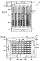
- an alternative reactor 70 comprises a stack of Fecralloy steel plates 71, each plate being generally rectangular, 125 mm long and 82 mm wide and 2 mm thick.
- each plate 71 is generally rectangular, 125 mm long and 82 mm wide and 2 mm thick.
- seven parallel rectangular grooves 72 are machined, each of depth 0.75 mm, with a header groove 74 of the same depth at each end, the header groove 74 extending to one side edge of the plate 71.
- the header groove 74 at the bottom end extends to the right hand edge of the plate 71, while that at the top end extends to the left hand edge of the plate 71.
- each rectangular groove 72 is three corrugated Fecralloy foils 76 a, b and c, each 50 ⁇ m thick and with its corrugations 1.8 mm high, but differing in the pitch or wavelength of their corrugations.
- holes 75 are provided at each end into which dowels locate.
- the stack of plates 71 and foils 76 is assembled and compressed during diffusion bonding, so that the foils are compressed to 1.5 mm in height.
- Gas flow plenums 78 are then brazed onto the stack at each corner, each plenum 78 communicating with one set of header grooves 74.
- an alternative reactor 80 has some similarities to the reactor 70 in comprising a stack of Fecralloy steel plates 81, each plate being generally rectangular, 125 mm long and 90 mm wide and 2 mm thick.
- each plate 81 is generally rectangular, 125 mm long and 90 mm wide and 2 mm thick.
- seven parallel rectangular grooves 82 are machined, each of width 4 mm and depth 0.75 mm, and at a separation of 5 mm, with a header groove 84 of the same depth at each end, the header groove 84 extending to a header aperture 83 near one side edge of the plate 81.
- the gas flow is therefore from the aperture 83 at the bottom left to the aperture 83 at the top right.
- each rectangular groove 82 is three corrugated Fecralloy foils 86 a, b and c, each 50 ⁇ m thick and with its corrugations 1.8 mm high, but differing in the pitch or wavelength of their corrugations.
- holes 85 are provided at each end into which dowels locate.
- the stack of plates 81 and foils 86 is assembled and compressed during diffusion bonding, so that the foils are compressed to 1.5 mm in height.
- Gas flow plenum connections are then made to the apertures 83 and 87 at the top of the stack, which are closed at the bottom of the stack.
- the reactor 80 differ from the reactor 70 in having integral headers defined by the apertures 83 and 87 (in place of the plenums 78), but in addition seven slots 88 through the plates 81 are defined in each land between the rectangular grooves 82, each slot 82 being 1 mm wide and 6 mm long. After assembly of the stack these slots 88 provide a flow path for a third gas stream, for example for pre-heating a gas stream.
Landscapes
- Chemical & Material Sciences (AREA)
- Organic Chemistry (AREA)
- Chemical Kinetics & Catalysis (AREA)
- Physics & Mathematics (AREA)
- Thermal Sciences (AREA)
- Engineering & Computer Science (AREA)
- Inorganic Chemistry (AREA)
- Combustion & Propulsion (AREA)
- General Health & Medical Sciences (AREA)
- Health & Medical Sciences (AREA)
- Fluid Mechanics (AREA)
- Physical Or Chemical Processes And Apparatus (AREA)
- Hydrogen, Water And Hydrids (AREA)
- Organic Low-Molecular-Weight Compounds And Preparation Thereof (AREA)
- Catalysts (AREA)
- Devices And Processes Conducted In The Presence Of Fluids And Solid Particles (AREA)
Claims (12)
- Katalytischer Reaktor, umfassend eine Vielzahl an Metallbögen oder -bahnen, angeordnet um erste Gasströmungskanäle zwischen benachbarten Bahnen zu bilden, Mittel zum Definieren zweiter Gasströmungskanäle in der Nähe der ersten Gasströmungskanäle, angeordnet, um guten thermischen Kontakt zwischen den Gasen in den ersten und den zweiten Gasströmungskanälen sicherzustellen, katalytisches Material auf mindestens einigen Oberflächen innerhalb jedes Strömungsskanals und Kopfelemente, um den Gasströmungskanälen Gasmischungen zuzuführen, wobei die Kopfelemente angeordnet sind, um den ersten und den zweiten Gasströmungskanälen verschiedene Gasmischungen zuzuführen, wobei die Metallbahnen flach sind und die ersten und zweiten Gasströmungskanäle durch Furchen in denselben definiert werden, so dass sich die Gase in den ersten und den zweiten Gasströmungskanälen im Druck um mehrere Atmosphären unterscheiden können und die Teile der Bahn zwischen den Furchen in Kontakt mit der benachbarten Metallbahn sind und so thermischen Kontakt zur Verfügung stellen und die Metallbahnen als Stapel verbunden sind, gekennzeichnet durch gewellte Folien, die in den Gasströmungskanälen zur Verfügung gestellt werden, wobei die Folien aus einem Aluminium enthaltenden Ferritstahl sind, der einen anhaftenden Oxidüberzug aus Aluminiumoxid bildet, wenn er in Luft erhitzt wird, und die das katalytische Material auf ihren Oberflächen aufweisen.
- Katalytischer Reaktor, wie in Anspruch 1 beansprucht, worin die gewellten Metallfolien innerhalb der Strömungskanäle komprimiert werden.
- Katalytischer Reaktor, wie in Anspruch 1 oder 2 beansprucht, worin Wellen mit verschiedener Neigung, Wellenlänge oder Muster an aufeinanderfolgenden Positionen entlang des Flusskanals zur Verfügung gestellt werden.
- Katalytischer Reaktor, wie in einem der vorstehenden Ansprüche beansprucht, worin die gewellten Folien geformt sind, um das Vermischen des Fluids innerhalb des Strömungskanals zu fördern.
- Katalytischer Reaktor, wie in einem der vorstehenden Ansprüche beansprucht, worin mindestens einige der Gasströmungskanäle in Breite oder Tiefe entlang ihrer Länge variieren.
- Verfahren zur Durchführung chemischer Reaktionen zwischen Gasen, worin sich die Gasmischung, die den ersten Flusskanälen zugeführt wird, von der Gasmischung unterscheidet, die den zweiten Gasströmungskanälen zugeführt wird, wobei jede Gasmischung eine Reaktion durchmacht und eine der Reaktionen endotherm ist, während die andere Reaktion exotherm ist, so dass Wärme zwischen den benachbarten Kanälen übertragen wird, dadurch gekennzeichnet, dass man einen Reaktor verwendet, wie er in einem der vorstehenden Ansprüche beansprucht wird.
- Verfahren, wie in Anspruch 6 beansprucht, in dem die endotherme Reaktion die Methan/Dampf-Reformierung ist.
- Verfahren wie in Anspruch 7 beansprucht, in dem die Reformierungsreaktion bei erhöhtem Druck zwischen 200 kPa und 2 MPa durchgeführt wird.
- Verfahren zum Verarbeiten von Methan, um höher molekulargewichtige Kohlenwasserstoffe zu produzieren, wobei das Verfahren umfasst das Durchführen des Dampf/Methan-Reformierens in einem ersten katalytischen Reaktor, der erste und zweite Gasströmungskanäle aufweist, indem Dampf und Methan bei erhöhter Temperatur und Druck den ersten Gasströmungskanälen des ersten katalytischen Reaktors zugeführt werden, und das Durchführen einer Methanverbrennung, um innerhalb der zweiten Gasströmungskanäle des ersten katalytischen Reaktors Wärme zu generieren; das Bereitstellen der Gasmischung, die aus der Dampf/Methan-Reformierung resultiert, an einem zweiten katalytischen Reaktor, um eine Fischer-Tropsch Synthese durchzuführen; und das Kondensieren der flüssigen Komponenten der Fluidmischung, die aus der Fisch-Tropsch Synthese resultiert; worin mindestens der erste katalytische Reaktor ein katalytischer Reaktor ist, wie er in Anspruch 1 beansprucht wird.
- Verfahren, wie in Anspruch 9 beansprucht, das auch das Übertragen der Wärme die während der Fischer-Tropsch Synthese abgegeben wird, umfasst, um ein Gas vorzuwärmen, das zum ersten katalytischen Reaktor zugeführt wird.
- Verfahren, wie in Anspruch 9 oder 10 beansprucht, das auch das Übertragen von Wärme von der Gasmischung, die aus der Dampf/Methanreformierung resultiert, umfasst, um ein Gas vorzuheizen, das zum ersten katalytischen Reaktor zugeführt wird.
- Verfahren wie in Anspruch 9, Anspruch 10 oder Anspruch 11 beansprucht, das auch das Extrahieren kurzkettiger Kohlenwasserstoffe aus der Fluidmischung, die aus der Fischer-Tropsch Synthese resultiert, und das Rückführen dieser kurzkettigen Kohlenwasserstoffe zum zweiten katalytischen Reaktor umfasst, um nochmals die Fischer-Tropsch Synthese durchzulaufen.
Priority Applications (3)
| Application Number | Priority Date | Filing Date | Title |
|---|---|---|---|
| EP05007275A EP1559475B1 (de) | 2000-01-11 | 2001-01-10 | Katalytischer Reaktor |
| EP08100024A EP1905508A3 (de) | 2000-01-11 | 2001-01-10 | Katalytischer Reaktor |
| EP06125827A EP1764150A1 (de) | 2000-01-11 | 2001-01-10 | Katalytischer Reaktor |
Applications Claiming Priority (5)
| Application Number | Priority Date | Filing Date | Title |
|---|---|---|---|
| GB0000473 | 2000-01-11 | ||
| GBGB0000473.9A GB0000473D0 (en) | 2000-01-11 | 2000-01-11 | Catalytic reactor |
| GB0006620A GB0006620D0 (en) | 2000-03-20 | 2000-03-20 | Catalytic reactor |
| GB0006620 | 2000-03-20 | ||
| PCT/GB2001/000077 WO2001051194A1 (en) | 2000-01-11 | 2001-01-10 | Catalytic reactor |
Related Child Applications (1)
| Application Number | Title | Priority Date | Filing Date |
|---|---|---|---|
| EP05007275A Division EP1559475B1 (de) | 2000-01-11 | 2001-01-10 | Katalytischer Reaktor |
Publications (2)
| Publication Number | Publication Date |
|---|---|
| EP1248675A1 EP1248675A1 (de) | 2002-10-16 |
| EP1248675B1 true EP1248675B1 (de) | 2005-08-24 |
Family
ID=26243366
Family Applications (4)
| Application Number | Title | Priority Date | Filing Date |
|---|---|---|---|
| EP05007275A Expired - Lifetime EP1559475B1 (de) | 2000-01-11 | 2001-01-10 | Katalytischer Reaktor |
| EP01900200A Expired - Lifetime EP1248675B1 (de) | 2000-01-11 | 2001-01-10 | Katalytischer reaktor |
| EP06125827A Withdrawn EP1764150A1 (de) | 2000-01-11 | 2001-01-10 | Katalytischer Reaktor |
| EP08100024A Withdrawn EP1905508A3 (de) | 2000-01-11 | 2001-01-10 | Katalytischer Reaktor |
Family Applications Before (1)
| Application Number | Title | Priority Date | Filing Date |
|---|---|---|---|
| EP05007275A Expired - Lifetime EP1559475B1 (de) | 2000-01-11 | 2001-01-10 | Katalytischer Reaktor |
Family Applications After (2)
| Application Number | Title | Priority Date | Filing Date |
|---|---|---|---|
| EP06125827A Withdrawn EP1764150A1 (de) | 2000-01-11 | 2001-01-10 | Katalytischer Reaktor |
| EP08100024A Withdrawn EP1905508A3 (de) | 2000-01-11 | 2001-01-10 | Katalytischer Reaktor |
Country Status (14)
| Country | Link |
|---|---|
| US (3) | US7300635B2 (de) |
| EP (4) | EP1559475B1 (de) |
| JP (1) | JP4704649B2 (de) |
| KR (2) | KR100718831B1 (de) |
| CN (1) | CN1235675C (de) |
| AP (1) | AP1457A (de) |
| AU (1) | AU2001223877A1 (de) |
| BR (1) | BR0107557B1 (de) |
| CA (1) | CA2396191C (de) |
| DK (2) | DK1559475T3 (de) |
| MX (1) | MXPA02006855A (de) |
| NO (2) | NO332058B1 (de) |
| OA (1) | OA12158A (de) |
| WO (1) | WO2001051194A1 (de) |
Cited By (6)
| Publication number | Priority date | Publication date | Assignee | Title |
|---|---|---|---|---|
| DE102008005839A1 (de) * | 2008-01-24 | 2009-07-30 | Borit Leichtbau-Technik Gmbh | Verfahren zur thermischen Integration eines Brennstoffzellensystems und Brennstoffzellensystem |
| US7829602B2 (en) | 2007-01-19 | 2010-11-09 | Velocys, Inc. | Process and apparatus for converting natural gas to higher molecular weight hydrocarbons using microchannel process technology |
| US8100996B2 (en) | 2008-04-09 | 2012-01-24 | Velocys, Inc. | Process for upgrading a carbonaceous material using microchannel process technology |
| US8747656B2 (en) | 2008-10-10 | 2014-06-10 | Velocys, Inc. | Process and apparatus employing microchannel process technology |
| US9676623B2 (en) | 2013-03-14 | 2017-06-13 | Velocys, Inc. | Process and apparatus for conducting simultaneous endothermic and exothermic reactions |
| US9908093B2 (en) | 2008-04-09 | 2018-03-06 | Velocys, Inc. | Process for converting a carbonaceous material to methane, methanol and/or dimethyl ether using microchannel process technology |
Families Citing this family (102)
| Publication number | Priority date | Publication date | Assignee | Title |
|---|---|---|---|---|
| US6451864B1 (en) | 1999-08-17 | 2002-09-17 | Battelle Memorial Institute | Catalyst structure and method of Fischer-Tropsch synthesis |
| KR100718831B1 (ko) * | 2000-01-11 | 2007-05-17 | 컴팩트지티엘 피엘씨 | 촉매 반응기 |
| MX2007008365A (es) | 2001-01-10 | 2007-09-21 | Compactgtl Plc | Reactor catalitico. |
| DE10108380A1 (de) * | 2001-02-21 | 2002-09-05 | Deg Intense Technologies & Ser | Reaktor zur Durchführung von katalysierten Reaktionen |
| AU2002335499A1 (en) * | 2001-03-02 | 2002-09-19 | Mesosystems Technology, Inc. | Ammonia-based hydrogen generation apparatus and method for using same |
| GB0116894D0 (en) * | 2001-07-11 | 2001-09-05 | Accentus Plc | Catalytic reactor |
| JP4923360B2 (ja) * | 2001-09-04 | 2012-04-25 | トヨタ自動車株式会社 | 薄板積層構造を有する水蒸気混合装置を備えた燃料改質装置、水蒸気混合装置、及び、水蒸気混合装置の製造方法 |
| DE60203018T2 (de) * | 2001-10-12 | 2005-07-07 | Gtl Microsystems Ag | Katalytischer reaktor |
| GB0125035D0 (en) * | 2001-10-18 | 2001-12-12 | Accentus Plc | Catalytic reactor |
| GB0124999D0 (en) * | 2001-10-18 | 2001-12-05 | Accentus Plc | Catalytic reactor |
| GB0125000D0 (en) * | 2001-10-18 | 2001-12-05 | Accentus Plc | Catalytic reactor |
| GB0129054D0 (en) * | 2001-12-05 | 2002-01-23 | Accentus Plc | Catalytic reactor and process |
| AU2002349143A1 (en) * | 2001-12-05 | 2003-06-17 | GTL Mircosystems AG | Process an apparatus for steam-methane reforming |
| AUPR981702A0 (en) * | 2002-01-04 | 2002-01-31 | Meggitt (Uk) Limited | Steam reformer |
| US7967878B2 (en) * | 2002-01-04 | 2011-06-28 | Meggitt (Uk) Limited | Reformer apparatus and method |
| US20040060238A1 (en) * | 2002-08-02 | 2004-04-01 | Retallick William B. | Autothermal catalytic steam reformer |
| US7179313B2 (en) * | 2002-08-02 | 2007-02-20 | Catacel Corp. | Regenerative autothermal catalytic steam reformer |
| US7250151B2 (en) * | 2002-08-15 | 2007-07-31 | Velocys | Methods of conducting simultaneous endothermic and exothermic reactions |
| US7014835B2 (en) | 2002-08-15 | 2006-03-21 | Velocys, Inc. | Multi-stream microchannel device |
| GB0314790D0 (en) | 2003-06-25 | 2003-07-30 | Accentus Plc | Catalytic reactor and process |
| WO2004078643A1 (en) * | 2003-03-05 | 2004-09-16 | Gtl Microsystems Ag | Producing longer-chain hydrocarbons from natural gas |
| GB0304949D0 (en) * | 2003-03-05 | 2003-04-09 | Accentus Plc | Catalytic reactor and process |
| WO2004082823A1 (ja) * | 2003-03-19 | 2004-09-30 | Tosoh Corporation | 微小流路構造体 |
| US7220699B2 (en) * | 2003-03-31 | 2007-05-22 | Intelligent Energy, Inc. | Catalyst incorporation in a microreactor |
| DE10317451A1 (de) * | 2003-04-16 | 2004-11-18 | Degussa Ag | Reaktor für heterogen katalysierte Reaktionen |
| US8580211B2 (en) * | 2003-05-16 | 2013-11-12 | Velocys, Inc. | Microchannel with internal fin support for catalyst or sorption medium |
| US7763217B2 (en) | 2003-05-16 | 2010-07-27 | Battelle Memorial Institute | Rapid start fuel reforming systems and techniques |
| US7276096B2 (en) * | 2003-06-27 | 2007-10-02 | Ultracell Corporation | Fuel processor dewar and methods |
| US20060156627A1 (en) * | 2003-06-27 | 2006-07-20 | Ultracell Corporation | Fuel processor for use with portable fuel cells |
| US8821832B2 (en) | 2003-06-27 | 2014-09-02 | UltraCell, L.L.C. | Fuel processor for use with portable fuel cells |
| GB0315180D0 (en) * | 2003-06-28 | 2003-08-06 | Accentus Plc | Combustion of gaseous fuel |
| JP2005103399A (ja) * | 2003-09-29 | 2005-04-21 | Casio Comput Co Ltd | 反応装置及び反応方法 |
| US20050142049A1 (en) * | 2003-12-31 | 2005-06-30 | Amsden Jeffrey M. | Multi-tubular reactors with monolithic catalysts |
| DE102004007344A1 (de) * | 2004-02-14 | 2005-09-01 | Robert Bosch Gmbh | Integrierter Reaktor zur thermischen Kopplung von Reaktionen und Verfahren zur Steuerung des Temperaturfeldes in einem solchen Reaktor |
| WO2005080259A1 (en) * | 2004-02-17 | 2005-09-01 | Modine Manufacturing Company | Integrated fuel processor for distributed hydrogen production |
| JP4580664B2 (ja) * | 2004-03-01 | 2010-11-17 | 大日本印刷株式会社 | マイクロリアクターおよびその製造方法 |
| KR100542201B1 (ko) * | 2004-03-03 | 2006-01-10 | 삼성에스디아이 주식회사 | 연료 전지 시스템의 개질기 및 이를 채용한 연료 전지시스템 |
| GB0405786D0 (en) * | 2004-03-16 | 2004-04-21 | Accentus Plc | Processing natural gas to form longer-chain hydrocarbons |
| GB0405796D0 (en) | 2004-03-16 | 2004-04-21 | Accentus Plc | Converting natural gas to longer-chain hydrocarbons |
| US8062623B2 (en) * | 2004-10-15 | 2011-11-22 | Velocys | Stable, catalyzed, high temperature combustion in microchannel, integrated combustion reactors |
| US7195652B2 (en) | 2004-04-06 | 2007-03-27 | Angstrom Power | Method for forming compact chemical reactors with reactor frames |
| WO2005097311A1 (en) * | 2004-04-06 | 2005-10-20 | Angstrom Power Incorporated | Chemical reactors and methods for making same |
| US7052795B2 (en) | 2004-04-06 | 2006-05-30 | Angstrom Power | Compact chemical reactor |
| US7067217B2 (en) | 2004-04-06 | 2006-06-27 | Angstrom Power | Compact fuel cell layer |
| US7458997B2 (en) | 2004-04-06 | 2008-12-02 | Angstrom Power Incorporated | Method for making compact chemical reactors |
| US7063910B2 (en) | 2004-04-06 | 2006-06-20 | Angstrom Power | Compact chemical reactor with reactor frame |
| GB0408896D0 (en) * | 2004-04-20 | 2004-05-26 | Accentus Plc | Catalytic reactor |
| US20050282100A1 (en) * | 2004-06-07 | 2005-12-22 | Arlo Lin | Catalyzer for gas-consuming device |
| US7743499B2 (en) * | 2004-12-20 | 2010-06-29 | Gm Global Technology Operations, Inc. | Reactor manufacturing method for a fuel cell processor |
| KR20060080385A (ko) * | 2005-01-05 | 2006-07-10 | 삼성에스디아이 주식회사 | 연료 전지 시스템, 개질기, 반응 기판 및 그 반응 기판의제조 방법 |
| GB0501731D0 (en) | 2005-01-31 | 2005-03-02 | Accentus Plc | Catalytic reactor |
| US7514387B2 (en) * | 2005-02-15 | 2009-04-07 | Umicore Ag & Co. Kg | Reformer and method of making the same |
| GB0504622D0 (en) | 2005-03-05 | 2005-04-13 | Accentus Plc | Catalytic reactors |
| US20060225347A1 (en) * | 2005-04-12 | 2006-10-12 | Dong-Uk Lee | Reformer for fuel cell system |
| GB0515276D0 (en) | 2005-07-26 | 2005-08-31 | Accentus Plc | Catalyst |
| ITRM20050532A1 (it) * | 2005-10-26 | 2007-04-27 | Technip Kti S P A | Apparato di combustione catalitica controllata accoppiata a reazioni endotermiche. |
| GB0603609D0 (en) | 2006-02-23 | 2006-04-05 | Accentus Plc | Catalyst structure |
| EP2026901B1 (de) * | 2006-04-07 | 2017-02-22 | Chart Industries, Inc. | Überkritisches verfahren, reaktor und system für wasserstoffproduktion |
| GB0608277D0 (en) | 2006-04-27 | 2006-06-07 | Accentus Plc | Process for preparing liquid hydrocarbons |
| GB0608927D0 (en) * | 2006-05-08 | 2006-06-14 | Accentus Plc | Catalytic Reactor |
| BRPI0711443A2 (pt) | 2006-05-08 | 2011-11-01 | Compactgtl Plc | reator catalìtico compacto, métodos de realizar combustão, e de realizar uma reação rápida no mesmo, e, de controlar o gradiente térmico em um reator catalìtico |
| KR100810965B1 (ko) * | 2006-05-29 | 2008-03-10 | 주식회사 엘지화학 | 다단계 반응용 마이크로 채널 반응 장치 |
| US7820725B2 (en) | 2006-09-05 | 2010-10-26 | Velocys, Inc. | Integrated microchannel synthesis and separation |
| US20080260575A1 (en) * | 2007-04-17 | 2008-10-23 | Honeywell International Inc. | Two-stage catox apparatus and process |
| MY180104A (en) | 2007-10-02 | 2020-11-23 | Compactgtl Plc | Gas-to-liquid plant using parallel units |
| DE102008017342A1 (de) * | 2008-04-04 | 2009-10-08 | Linde Aktiengesellschaft | Kompaktreaktor |
| US7976797B2 (en) * | 2008-04-08 | 2011-07-12 | Exxonmobil Chemical Patents Inc. | Advanced materials for regenerative pyrolysis reactors, methods, and reactors using the same |
| ITVR20080069A1 (it) * | 2008-06-18 | 2009-12-19 | I C I Caldaie S P A | Dispositivo catalizzatore |
| US8278231B2 (en) * | 2008-11-24 | 2012-10-02 | Exxonmobil Chemical Patents Inc. | Heat stable formed ceramic, apparatus and method of using the same |
| US8450552B2 (en) * | 2009-05-18 | 2013-05-28 | Exxonmobil Chemical Patents Inc. | Pyrolysis reactor materials and methods |
| JP5581028B2 (ja) * | 2009-09-16 | 2014-08-27 | 住友精密工業株式会社 | 触媒反応器 |
| KR101112662B1 (ko) * | 2010-04-05 | 2012-02-15 | 주식회사 아모그린텍 | 대용량 금속 촉매 담체 및 이를 이용한 촉매 컨버터 |
| GB201007196D0 (en) | 2010-04-30 | 2010-06-16 | Compactgtl Plc | Gas-to-liquid technology |
| US20120051993A1 (en) * | 2010-08-25 | 2012-03-01 | L'air Liquide Societe Anonyme Pour L'etude Et L'exploitation Des Procedes Georges Claude | Mitigation System In A Steam Methane Reformer Plant |
| GB201118465D0 (en) | 2011-10-26 | 2011-12-07 | Compactgtl Plc | Gas-to-liquid technology |
| GB201120327D0 (en) | 2011-11-24 | 2012-01-04 | Compactgtl Plc | Oil well product treatment |
| WO2013093423A1 (en) | 2011-12-19 | 2013-06-27 | Compactgtl Limited | Process for the regeneration of a fischer tropsch catalyst |
| WO2013093428A1 (en) | 2011-12-19 | 2013-06-27 | Compactgtl Limited | Operation of a fischer - tropsch catalytic process |
| GB201122193D0 (en) * | 2011-12-22 | 2012-02-01 | Compact Gtl Plc | Catalytic reactor and catalyst structure |
| US11607657B2 (en) | 2012-02-06 | 2023-03-21 | Helbio S.A. | Heat integrated reformer with catalytic combustion for hydrogen production |
| WO2013117948A1 (en) | 2012-02-06 | 2013-08-15 | Helbio Societé Anonyme Hydrogen And Energy Production Systems | Heat integrated reformer with catalytic combustion for hydrogen production |
| JP2015517175A (ja) * | 2012-03-08 | 2015-06-18 | ヘルビオ ソシエテ アノニム ハイドロジェン アンド エナジー プロダクション システムズ | 燃料電池のための触媒を支持する置換可能な構造化支持部を含む触媒加熱式燃料処理装置 |
| EP2653765B1 (de) * | 2012-04-20 | 2019-02-27 | TI Automotive (Heidelberg) GmbH | Rohrleitung für ein zu temperierendes fluides Medium |
| US8574501B1 (en) | 2012-05-16 | 2013-11-05 | Greenway Innovative Energy, Inc. | Natural gas to liquid fuels |
| JP6041162B2 (ja) * | 2012-08-01 | 2016-12-07 | 国立大学法人九州大学 | 炭化水素の改質用のペーパー状触媒及びペーパー状触媒配列体並びにペーパー状触媒又はペーパー状触媒配列体を備えた固体酸化物形燃料電池 |
| JP6084394B2 (ja) * | 2012-08-09 | 2017-02-22 | 株式会社Ti | 水素発生装置の反応セル構造 |
| KR101401355B1 (ko) * | 2012-11-21 | 2014-06-02 | 한국과학기술연구원 | 탄화수소 개질용 마이크로 채널 반응기 |
| JP6408754B2 (ja) * | 2013-02-06 | 2018-10-17 | 株式会社Ihi | リアクタ |
| GB2527592A (en) * | 2014-06-27 | 2015-12-30 | Compactgtl Ltd | Catalytic reactors |
| JP6728739B2 (ja) | 2016-02-12 | 2020-07-22 | 株式会社Ihi | 反応装置 |
| CN106076220A (zh) * | 2016-08-02 | 2016-11-09 | 杭州沈氏节能科技股份有限公司 | 一种气固相微反应器 |
| EP3532430B1 (de) * | 2016-10-25 | 2020-07-01 | Technip France | Katalysatorrohr für dampfreformierung |
| CN107115828A (zh) * | 2017-06-17 | 2017-09-01 | 福建德兴节能科技有限公司 | 高效催化器及其用途 |
| KR101980631B1 (ko) | 2017-08-25 | 2019-05-21 | 국방과학연구소 | 연료의 흡열성능을 시험하기 위한 열 교환 장치 및 흡열성능시험방법 |
| EP3710399A4 (de) * | 2017-11-16 | 2021-07-21 | Societé de Commercialisation des Produits de la Recherche Appliquée SOCPRA Sciences et Génie S.E.C | Integrierte solarmikroreaktoren zur wasserstoffsynthese durch dampfmethanreformierung |
| US10822233B2 (en) * | 2018-05-11 | 2020-11-03 | Doosan Fuel Cell America, Inc. | Reformer including catalyst in an inlet plenum |
| CN108636301B (zh) * | 2018-07-05 | 2023-07-25 | 鄂尔多斯应用技术学院 | 一种化工实验室固定床模块化反应装置 |
| WO2020111016A1 (ja) | 2018-11-26 | 2020-06-04 | 株式会社Ihi | 反応装置 |
| CN114390946A (zh) * | 2019-11-13 | 2022-04-22 | 株式会社Ihi | 将填充部件插入反应装置中的夹具 |
| KR102806211B1 (ko) * | 2022-03-23 | 2025-05-14 | 한국에너지기술연구원 | 과불화 화합물 처리장치 및 그 처리방법 |
| KR20240175156A (ko) * | 2023-06-12 | 2024-12-19 | 주식회사 엘지화학 | 전기 가열 반응기 |
| WO2025245082A1 (en) * | 2024-05-20 | 2025-11-27 | Dimensional Energy, Inc. | Systems and methods for catalytic chemical reactions |
Family Cites Families (51)
| Publication number | Priority date | Publication date | Assignee | Title |
|---|---|---|---|---|
| US3127247A (en) * | 1964-03-31 | Alternate annular isothermal reactor | ||
| GB1490977A (en) | 1973-12-10 | 1977-11-09 | Atomic Energy Authority Uk | Catalysts |
| GB1546097A (en) | 1975-08-20 | 1979-05-16 | Atomic Energy Authority Uk | Fabricating catalyst bodies |
| SE422744B (sv) * | 1975-08-20 | 1982-03-29 | Atomic Energy Authority Uk | Katalysatorkropp med genomgaende kanaler jemte sett for dess tillverkning |
| GB1531134A (en) * | 1975-08-20 | 1978-11-01 | Atomic Energy Authority Uk | Methods of fabricating bodies and to bodies so fabricated |
| JPS5556823A (en) * | 1978-10-19 | 1980-04-26 | Daikin Ind Ltd | Catalytic oxidation apparatus |
| CA1146148A (en) | 1981-06-30 | 1983-05-10 | James Den Hartog | Ordered bed packing module |
| JPS61171870A (ja) * | 1985-01-28 | 1986-08-02 | Houyuu:Kk | 改質天然ガスを用いた内燃機関 |
| GB8626532D0 (en) * | 1986-11-06 | 1986-12-10 | British Petroleum Co Plc | Chemical process |
| DK156701C (da) * | 1987-08-27 | 1990-01-29 | Haldor Topsoe As | Fremgangsmaade til gennemfoerelse af heterogene katalytiske kemiske reaktioner |
| US4815534A (en) * | 1987-09-21 | 1989-03-28 | Itt Standard, Itt Corporation | Plate type heat exchanger |
| KR940005668B1 (ko) * | 1988-08-13 | 1994-06-22 | 우스이 고꾸사이 산교 가부시끼가이샤 | 배기가스 정화용 촉매를 담지하기 위한 금속제 담지모체(擔持母體) |
| FR2657273B1 (fr) * | 1990-01-19 | 1992-05-15 | Inst Francais Du Petrole | Enceinte reactionnelle comprenant un reacteur calandre et des moyens de stratification du courant d'un fluide caloporteur. |
| DE4016276C1 (de) * | 1990-05-21 | 1991-06-20 | Behr Gmbh & Co | |
| JPH0815559B2 (ja) | 1990-11-13 | 1996-02-21 | 新日本製鐵株式会社 | 耐熱応力・耐熱疲労特性の優れたレーストラック型自動車排ガス触媒用金属担体 |
| JPH05105405A (ja) * | 1991-10-21 | 1993-04-27 | Ishikawajima Harima Heavy Ind Co Ltd | プレート型リフオーマ |
| JPH05196386A (ja) * | 1991-11-22 | 1993-08-06 | Nippondenso Co Ltd | 積層プレート式熱交換器 |
| US5846494A (en) * | 1992-04-30 | 1998-12-08 | Gaiser; Gerd | Reactor for catalytically processing gaseous fluids |
| US5328359A (en) * | 1992-05-19 | 1994-07-12 | W. R. Grace & Co.-Conn. | Ignition stage for a high temperature combustor |
| US5250270A (en) * | 1992-07-17 | 1993-10-05 | The M. W. Kellogg Company | Catalytic reactor bed |
| SE470581B (sv) | 1993-02-26 | 1994-10-03 | Sandvik Ab | Bärarkropp av metallfolie för katalysator |
| KR100327521B1 (ko) * | 1993-03-19 | 2002-07-03 | 이.아이,듀우판드네모아앤드캄파니 | 일체형화학가공장치및그제조방법 |
| US5534328A (en) * | 1993-12-02 | 1996-07-09 | E. I. Du Pont De Nemours And Company | Integrated chemical processing apparatus and processes for the preparation thereof |
| US5600052A (en) * | 1994-05-02 | 1997-02-04 | Uop | Process and apparatus for controlling reaction temperatures |
| DE59503581D1 (de) * | 1994-06-15 | 1998-10-22 | Dbb Fuel Cell Engines Gmbh | Zweistufige Methanol-Reformierung |
| US5811062A (en) | 1994-07-29 | 1998-09-22 | Battelle Memorial Institute | Microcomponent chemical process sheet architecture |
| US5611214A (en) * | 1994-07-29 | 1997-03-18 | Battelle Memorial Institute | Microcomponent sheet architecture |
| JPH08106197A (ja) * | 1994-10-06 | 1996-04-23 | Toshiba Corp | 画像形成装置 |
| US5681538A (en) | 1995-02-01 | 1997-10-28 | Engelhard Corporation | Metallic monolith and plates for the assembly thereof |
| DE19524158A1 (de) * | 1995-07-03 | 1997-01-09 | Degussa | Verfahren zur Herstellung von Blausäure |
| CN1166032A (zh) * | 1995-12-29 | 1997-11-26 | 奎德/技术公司 | 包装计算机盘的方法 |
| DE19617396C2 (de) * | 1996-05-02 | 1998-03-26 | Dornier Gmbh | Strömungsmodul |
| JPH10151356A (ja) * | 1996-11-21 | 1998-06-09 | Matsushita Electric Ind Co Ltd | 燃焼用触媒部材 |
| DE19654361A1 (de) | 1996-12-24 | 1998-06-25 | Behr Gmbh & Co | Reaktor in Stapelbauweise |
| JPH10273304A (ja) * | 1997-03-28 | 1998-10-13 | Sekiyu Sangyo Kasseika Center | 熱交換型改質反応器 |
| DE19725378A1 (de) * | 1997-06-16 | 1998-12-17 | Gerhard Friedrich | Kompakter Festbettreaktor für katalytische Reaktionen mit integriertem Wärmeaustausch |
| DE19725665A1 (de) * | 1997-06-18 | 1998-12-24 | Lubo Maschf | Vorrichtung zum Sortieren von Abfallmaterialien |
| US6200536B1 (en) | 1997-06-26 | 2001-03-13 | Battelle Memorial Institute | Active microchannel heat exchanger |
| DE19743673C2 (de) | 1997-10-02 | 2002-05-08 | Xcellsis Gmbh | Vorrichtung zur Wasserstofferzeugung aus Kohlenwasserstoffen und Verfahren zur Herstellung eines Katalysators |
| DE19746251C2 (de) * | 1997-10-20 | 1999-09-09 | Dbb Fuel Cell Engines Gmbh | Anlage zur Wasserdampfreformierung eines Kohlenwasserstoffs und Betriebsverfahren hierfür |
| DE19754012C2 (de) * | 1997-12-05 | 1999-11-11 | Dbb Fuel Cell Engines Gmbh | Anlage zur Wasserdampfreformierung eines Kohlenwasserstoffs |
| ZA99313B (en) | 1998-01-20 | 1999-07-19 | Shell Int Research | Catalyst suitable for the preparation of hydrogen and carbon monoxide from a hydrocarbonaceous feedstock |
| US6098396A (en) * | 1998-05-27 | 2000-08-08 | Solar Turbines Inc. | Internal combustion engine having a catalytic reactor |
| DE19825102C2 (de) | 1998-06-05 | 2001-09-27 | Xcellsis Gmbh | Verfahren zur Herstellung eines kompakten katalytischen Reaktors |
| US6180846B1 (en) * | 1998-09-08 | 2001-01-30 | Uop Llc | Process and apparatus using plate arrangement for combustive reactant heating |
| US6168765B1 (en) * | 1998-09-08 | 2001-01-02 | Uop Llc | Process and apparatus for interbed injection in plate reactor arrangement |
| US6284217B1 (en) | 1999-08-17 | 2001-09-04 | Battelle Memorial Institute | Method and catalyst structure for steam reforming of a hydrocarbon |
| KR100718831B1 (ko) * | 2000-01-11 | 2007-05-17 | 컴팩트지티엘 피엘씨 | 촉매 반응기 |
| DE60203018T2 (de) * | 2001-10-12 | 2005-07-07 | Gtl Microsystems Ag | Katalytischer reaktor |
| GB0125000D0 (en) * | 2001-10-18 | 2001-12-05 | Accentus Plc | Catalytic reactor |
| GB0408896D0 (en) * | 2004-04-20 | 2004-05-26 | Accentus Plc | Catalytic reactor |
-
2001
- 2001-01-10 KR KR1020027008896A patent/KR100718831B1/ko not_active Expired - Fee Related
- 2001-01-10 JP JP2001551604A patent/JP4704649B2/ja not_active Expired - Lifetime
- 2001-01-10 US US10/169,901 patent/US7300635B2/en not_active Expired - Lifetime
- 2001-01-10 CN CNB018063683A patent/CN1235675C/zh not_active Expired - Lifetime
- 2001-01-10 MX MXPA02006855A patent/MXPA02006855A/es active IP Right Grant
- 2001-01-10 WO PCT/GB2001/000077 patent/WO2001051194A1/en not_active Ceased
- 2001-01-10 EP EP05007275A patent/EP1559475B1/de not_active Expired - Lifetime
- 2001-01-10 BR BRPI0107557-8A patent/BR0107557B1/pt not_active IP Right Cessation
- 2001-01-10 DK DK05007275T patent/DK1559475T3/da active
- 2001-01-10 KR KR1020067023012A patent/KR100771391B1/ko not_active Expired - Fee Related
- 2001-01-10 CA CA002396191A patent/CA2396191C/en not_active Expired - Lifetime
- 2001-01-10 AP APAP/P/2002/002574A patent/AP1457A/en active
- 2001-01-10 EP EP01900200A patent/EP1248675B1/de not_active Expired - Lifetime
- 2001-01-10 EP EP06125827A patent/EP1764150A1/de not_active Withdrawn
- 2001-01-10 DK DK01900200T patent/DK1248675T3/da active
- 2001-01-10 OA OA1200200207A patent/OA12158A/en unknown
- 2001-01-10 AU AU2001223877A patent/AU2001223877A1/en not_active Abandoned
- 2001-01-10 EP EP08100024A patent/EP1905508A3/de not_active Withdrawn
-
2002
- 2002-07-09 NO NO20023320A patent/NO332058B1/no not_active IP Right Cessation
-
2006
- 2006-10-30 NO NO20064969A patent/NO20064969L/no not_active Application Discontinuation
-
2007
- 2007-11-27 US US11/987,136 patent/US7670393B2/en not_active Expired - Lifetime
-
2008
- 2008-01-29 US US12/010,754 patent/US7695694B2/en not_active Expired - Lifetime
Cited By (8)
| Publication number | Priority date | Publication date | Assignee | Title |
|---|---|---|---|---|
| US7829602B2 (en) | 2007-01-19 | 2010-11-09 | Velocys, Inc. | Process and apparatus for converting natural gas to higher molecular weight hydrocarbons using microchannel process technology |
| DE102008005839A1 (de) * | 2008-01-24 | 2009-07-30 | Borit Leichtbau-Technik Gmbh | Verfahren zur thermischen Integration eines Brennstoffzellensystems und Brennstoffzellensystem |
| US8100996B2 (en) | 2008-04-09 | 2012-01-24 | Velocys, Inc. | Process for upgrading a carbonaceous material using microchannel process technology |
| US9908093B2 (en) | 2008-04-09 | 2018-03-06 | Velocys, Inc. | Process for converting a carbonaceous material to methane, methanol and/or dimethyl ether using microchannel process technology |
| US8747656B2 (en) | 2008-10-10 | 2014-06-10 | Velocys, Inc. | Process and apparatus employing microchannel process technology |
| US9695368B2 (en) | 2008-10-10 | 2017-07-04 | Velocys, Inc. | Process and apparatus employing microchannel process technology |
| US9926496B2 (en) | 2008-10-10 | 2018-03-27 | Velocys, Inc. | Process and apparatus employing microchannel process technology |
| US9676623B2 (en) | 2013-03-14 | 2017-06-13 | Velocys, Inc. | Process and apparatus for conducting simultaneous endothermic and exothermic reactions |
Also Published As
Similar Documents
| Publication | Publication Date | Title |
|---|---|---|
| EP1248675B1 (de) | Katalytischer reaktor | |
| RU2415701C2 (ru) | Каталитический реактор | |
| AU2002314372A1 (en) | Catalytic reactor | |
| US7223373B2 (en) | Catalytic reactor | |
| JP2003519563A5 (de) | ||
| EP1434652A1 (de) | Katalytischer reaktor | |
| CN100415358C (zh) | 催化反应器 |
Legal Events
| Date | Code | Title | Description |
|---|---|---|---|
| PUAI | Public reference made under article 153(3) epc to a published international application that has entered the european phase |
Free format text: ORIGINAL CODE: 0009012 |
|
| 17P | Request for examination filed |
Effective date: 20020716 |
|
| AK | Designated contracting states |
Kind code of ref document: A1 Designated state(s): AT BE CH CY DE DK ES FI FR GB GR IE IT LI LU MC NL PT SE TR |
|
| AX | Request for extension of the european patent |
Free format text: AL;LT;LV;MK;RO;SI |
|
| 17Q | First examination report despatched |
Effective date: 20040223 |
|
| RBV | Designated contracting states (corrected) |
Designated state(s): AT BE CH DE DK FR GB LI |
|
| GRAP | Despatch of communication of intention to grant a patent |
Free format text: ORIGINAL CODE: EPIDOSNIGR1 |
|
| RBV | Designated contracting states (corrected) |
Designated state(s): DK FR GB |
|
| REG | Reference to a national code |
Ref country code: DE Ref legal event code: 8566 |
|
| GRAS | Grant fee paid |
Free format text: ORIGINAL CODE: EPIDOSNIGR3 |
|
| GRAA | (expected) grant |
Free format text: ORIGINAL CODE: 0009210 |
|
| AK | Designated contracting states |
Kind code of ref document: B1 Designated state(s): DK FR GB |
|
| REG | Reference to a national code |
Ref country code: GB Ref legal event code: FG4D |
|
| REG | Reference to a national code |
Ref country code: DK Ref legal event code: T3 |
|
| ET | Fr: translation filed | ||
| PLBE | No opposition filed within time limit |
Free format text: ORIGINAL CODE: 0009261 |
|
| STAA | Information on the status of an ep patent application or granted ep patent |
Free format text: STATUS: NO OPPOSITION FILED WITHIN TIME LIMIT |
|
| 26N | No opposition filed |
Effective date: 20060526 |
|
| REG | Reference to a national code |
Ref country code: GB Ref legal event code: 732E |
|
| REG | Reference to a national code |
Ref country code: FR Ref legal event code: TP |
|
| PGFP | Annual fee paid to national office [announced via postgrant information from national office to epo] |
Ref country code: FR Payment date: 20130213 Year of fee payment: 13 |
|
| REG | Reference to a national code |
Ref country code: GB Ref legal event code: 732E Free format text: REGISTERED BETWEEN 20131003 AND 20131009 |
|
| REG | Reference to a national code |
Ref country code: FR Ref legal event code: ST Effective date: 20140930 |
|
| PG25 | Lapsed in a contracting state [announced via postgrant information from national office to epo] |
Ref country code: FR Free format text: LAPSE BECAUSE OF NON-PAYMENT OF DUE FEES Effective date: 20140131 |
|
| PGFP | Annual fee paid to national office [announced via postgrant information from national office to epo] |
Ref country code: DK Payment date: 20200123 Year of fee payment: 20 Ref country code: GB Payment date: 20200123 Year of fee payment: 20 |
|
| REG | Reference to a national code |
Ref country code: DK Ref legal event code: EUP Expiry date: 20210110 |
|
| REG | Reference to a national code |
Ref country code: GB Ref legal event code: PE20 Expiry date: 20210109 |
|
| PG25 | Lapsed in a contracting state [announced via postgrant information from national office to epo] |
Ref country code: GB Free format text: LAPSE BECAUSE OF EXPIRATION OF PROTECTION Effective date: 20210109 |