EP1246302A2 - Schneidvorrichtung für ein Werkzeug, insbesondere für einen Schraubendreher - Google Patents
Schneidvorrichtung für ein Werkzeug, insbesondere für einen Schraubendreher Download PDFInfo
- Publication number
- EP1246302A2 EP1246302A2 EP02005930A EP02005930A EP1246302A2 EP 1246302 A2 EP1246302 A2 EP 1246302A2 EP 02005930 A EP02005930 A EP 02005930A EP 02005930 A EP02005930 A EP 02005930A EP 1246302 A2 EP1246302 A2 EP 1246302A2
- Authority
- EP
- European Patent Office
- Prior art keywords
- clamping piece
- cutting device
- piece attachment
- attachment
- cutting
- Prior art date
- Legal status (The legal status is an assumption and is not a legal conclusion. Google has not performed a legal analysis and makes no representation as to the accuracy of the status listed.)
- Granted
Links
Images



Classifications
-
- B—PERFORMING OPERATIONS; TRANSPORTING
- B25—HAND TOOLS; PORTABLE POWER-DRIVEN TOOLS; MANIPULATORS
- B25B—TOOLS OR BENCH DEVICES NOT OTHERWISE PROVIDED FOR, FOR FASTENING, CONNECTING, DISENGAGING, OR HOLDING
- B25B15/00—Screwdrivers
-
- H—ELECTRICITY
- H02—GENERATION; CONVERSION OR DISTRIBUTION OF ELECTRIC POWER
- H02G—INSTALLATION OF ELECTRIC CABLES OR LINES, OR OF COMBINED OPTICAL AND ELECTRIC CABLES OR LINES
- H02G1/00—Methods or apparatus specially adapted for installing, maintaining, repairing or dismantling electric cables or lines
- H02G1/005—Methods or apparatus specially adapted for installing, maintaining, repairing or dismantling electric cables or lines for cutting cables or wires, or splicing
Definitions
- the invention relates to a cutting device for a tool, in particular for a screwdriver, with a sprag, which on a shaft, in particular the screwdriver can be pushed on and locked there.
- the invention aims at a cutting device to create, which the wiring of insulation penetrating cutting connections, especially of terminal blocks with insulation-piercing cutting connections facilitated.
- the invention achieves this aim by the subject matter of claim 1 the actuating lever and / or the clamping piece attachment have a cutting edge Cut through electrical cables or lines.
- the invention provides a cutting device, which is easy on each commercially available screwdriver can be retrofitted.
- the invention can by the spacers known from the prior art.
- clamping piece attachment it is also conceivable for the clamping piece attachment to be in one piece with the shaft or handle to train and thus screwdriver with sprag attachment or with Cutting device for sale as a unit.
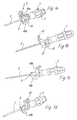
- FIG 1 shows a screwdriver 1 with a screwdriver handle 3 and a Shank 5. This is a standard screwdriver. This Screwdriver is also shown as a separate part in Figure 2a.
- a cutting device 7 according to the invention is placed on the screwdriver 1.
- the cutting device 7 has a clamping piece attachment 9 which extends over the shaft 5 the screwdriver is pushed.
- the operating lever 11 has two lever arms 11a and 11b, which extend to opposite sides of a pivot bearing 13 which is formed on the clamping piece attachment 9.
- An actuating button 15 is formed at the end of one lever arm 11a.
- the one Lever arm 11a opposite lever arm on the other side of the pivot bearing 13 has a curved shape, the towards the clamping piece attachment 9 lying edge of the lever arm 11b with one piece with the lever arm Cutting edge 17 is provided.
- a cable 19 is inserted into the space between the sprag attachment and the lever arm 11b with the cutting edge 17 inserted. Then will In FIG. 1, for example, with the thumb, the actuation button 15 is depressed, so that the cable 19 between the sprag attachment 9 and the lever arm 11b is first pinched, the cable being severed. The cable can then in a clamp, e.g. a terminal block with a cutting or IDC connection device be introduced (not shown here).
- a clamp e.g. a terminal block with a cutting or IDC connection device be introduced (not shown here).
- the particular advantage of the invention is that in particular with IDC connections next to a screwdriver to complete the connections basically no additional tool more is required. With the actual screwdriver can the clamp are operated. The cutting device placed on the screwdriver can be used to cut the cables.
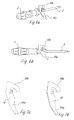
- a first clamping piece attachment 9 has a central bore 21, which passes through the clamping piece attachment in the middle. This hole serves to push the clamping piece onto the shaft.
- the clamping piece attachment 9 in FIG. 3 differs from the clamping piece attachment 9 from Figure 2 essentially in that a notch or groove 29 for the defined Guide the cable is formed on the clamping piece, which is the insertion of the cable facilitated in the area between the cutting edge 17 and the clamping piece attachment 9.
- the notch 29 is formed such that at the edge of the sprag attachment a type of cutting edge 31 is formed in the area of the notch, which either supports the function of the cutting edge 17 on the lever arm 11b or but this cutting edge function replaces when the operating lever is not with a such cutting edge is formed (e.g. Figures 6 and 10).
- 5a and 5b show the design of the actuating button 15 as a molded plastic part, which is simply on the otherwise preferably metallic operating lever or is pushed onto the lever arm 11a.
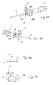
- Figure 6a shows a further embodiment of the invention, in which on the actuating lever 11 or on its lever arm 11a no separate actuation button 15 is trained. Rather, the lever arm 11a has a slightly curved shape Actuation with the index finger.
- the embodiment of Figure 6 differs differs from the embodiment of Figure 1 essentially in that instead of thumb actuation, preferably actuation by means of an index finger is chosen.
- FIGS. 7a and 7b show separate front and rear views of the actuating lever 11 from Figure 6.
- the elongated shape of the lever arm 11a can be clearly seen to ensure a good approach of the index and / or middle and / or ring finger.
- the actuation is in a further embodiment of the invention provided lever arm 11a in its end region with a kind of ring or eyelet 32 provided, which can also be operated by the index finger.
- FIG. 9 shows a variant in addition to the embodiments already shown of the invention, in which on the cutting device 7 between the sprag attachment 9 and the actuating button 15 facing away from the actuating lever 11, that is, on the lever arm 11a, a spring 33 is formed, which resets of the actuating lever 11 after a cable has been severed.
- FIGS. 10 it can be seen particularly well (see FIG. 10a). how to cut the cable 19 in practice.
- FIG. 10 differs from the embodiment of FIG Figure 1 essentially in that in addition to the cutting edge 17 on the operating lever 11 or as a replacement of this cutting edge also the clamping piece attachment 9, the here is made of plastic, with a placed on the clamping piece attachment 9 Cutting knife 35 is provided.
- FIG 10b Another difference of this embodiment can be seen in the fact that, as in FIG 10b recognizable, the clamping piece attachment 9 not only with a central bore 21 is provided, but also with a radially from the central bore 21 externally extending groove 34.
- the clamping piece attachment 9 is clamped here by means of a clamping screw 37, which has both the clamping piece and the groove 39 penetrates so that the two areas of the Clamp piece are pressed on both sides of the groove to each other, which the Clamp piece attachment locked on shaft 5.
- FIGS. 11a and 11b show the clamping piece attachment 9 with the groove 39 and the separate one Cutting knife 35, which functions here as a cutting edge and into a recess 41 is inserted on the side of the sprag attachment opposite the groove.
- the cutting knife 35 quasi between the sprag attachment 9 and the Operating lever 11.
Landscapes
- Engineering & Computer Science (AREA)
- Mechanical Engineering (AREA)
- Scissors And Nippers (AREA)
- Shearing Machines (AREA)
Abstract
Description
- Figur 1a ― 1d
- verschiedene perspektivische Ansichten eines Schraubendrehers mit einem ersten Ausführungsbeispiel einer erfindungsgemäßen Schneidvorrichtung,
- Figur 2a
- den Schraubendreher aus Fig. 1 ohne Schneidvorrichtung;
- Figur 2b ― 2d
- Ansichten des Klemmstückaufsatzes aus Figur 1;
- Figur 3a und 3b
- eine Variante eines Klemmstückaufsatzes;
- Figur 4a und 4b
- eine weitere Variante eines Klemmstückaufsatzes;
- Figur 5a und 5b
- Ansichten des Betätigungsknopfes aus Figur 1;
- Figur 6a und 6b
- Ansichten eines Schraubendrehers mit einer zweiten erfindungsgemäßen Schneidvorrichtung;
- Figur 7a und 7b
- Ansichten des Betätigungshebels aus Figur 6;
- Figuren 8 bis 10
- weitere Varianten von Schraubendrehern mit erfindungsgemäßen Schneidvorrichtungen;
- Figur 11a
- eine Ansicht des Betätigungshebels aus Figur 10;
- Figur 11b und 11c
- Ansichten des Klemmstückaufsatzes aus Figur 10 nebst Schneidmesser.
- 1
- Schraubendreher
- 3
- Schraubendrehergriff
- 5
- Schaft
- 7
- Aufsatz
- 9
- Klemmstückaufsatz
- 11
- Betätigungshebel
- 11a
- Hebelarm
- 11b
- Hebelarm
- 13
- Schwenklager
- 15
- Betätigungsknopf
- 17
- Schneidkante
- 19
- Kabel
- 21
- Bohrung
- 23
- Bohrung
- 25
- Bohrung
- 27
- Welle
- 29
- Nut
- 31
- Schneidkante
- 32
- Öse
- 33
- Feder
- 34
- Nut
- 35
- Schneidmesser
- 37
- Spannschraube
- 39
- Nut
- 41
- Ausnehmung
Claims (16)
- Schneidvorrichtung für ein Werkzeug, insbesondere für einen Schraubendreher (1), mit einem Klemmstückaufsatz (9), welcher auf einen Schaft (5), insbesondere des Schraubendrehers (1) aufschiebbar und dort arretierbar ist, wobei am Klemmstückaufsatz (9) ein Betätigungshebel (11) verschwenkbar gelagert ist und wobei der Betätigungshebel (11) und/oder der Klemmstückaufsatz (9) eine Schneidkante (17, 31, 35) zum Durchtrennen elektrischer Kabel oder Leitungen aufweist/aufweisen.
- Schneidvorrichtung nach Anspruch 1, dadurch gekennzeichnet, daß der Klemmstückaufsatz (9) am Schaft (5) des Schraubendrehers (1) mittels einer Klemmoder Spannschraube (37) festklemmbar ist.
- Schneidvorrichtung nach einem der vorstehenden Ansprüche, dadurch gekennzeichnet, daß der Betätigungshebel (11) am Klemmstückaufsatz (9) verschwenkbar gelagert ist und einen ersten Hebelarm (11a) zur Betätigung sowie einen zweiten Hebelarm (11b) zum Durchtrennen des Leiters oder Kabels zwischen dem Klemmstückaufsatz (9) und dem Betätigungshebel (11) aufweist.
- Schneidvorrichtung nach einem der vorstehenden Ansprüche, dadurch gekennzeichnet, daß der Hebelarm (11b) eine gebogene Form aufweist.
- Schneidvorrichtung nach einem der vorstehenden Ansprüche, dadurch gekennzeichnet, daß auf den Hebelarm (11a) ein Betätigungsknopf (15) aufsetzbar ist.
- Schneidvorrichtung nach einem der vorstehenden Ansprüche, dadurch gekennzeichnet, daß der Klemmstückaufsatz (9) von einer mittigen Bohrung (21) zum Aufschieben des Klemmstückaufsatzes (9) auf den Schaft (5) des Schraubendrehers durchsetzt ist.
- Schneidvorrichtung nach einem der vorstehenden Ansprüche, dadurch gekennzeichnet, daß am Klemmstückaufsatz (9) eine Einkerbung (29) zum Führen des Kabels und/oder Leiters ausgebildet ist.
- Schneidvorrichtung nach einem der vorstehenden Ansprüche, dadurch gekennzeichnet, daß die Einkerbung (29) in ihrem Randbereich klingenartig/scharfkantig ausgebildet ist.
- Schneidvorrichtung nach einem der Ansprüche 1 bis 8, dadurch gekennzeichnet, daß die Schneidkante einstückig mit dem Klemmstückaufsatz (9) oder dem Betätigungshebel (11) ausgebildet ist.
- Schneidvorrichtung nach einem der Ansprüche 1 bis 8, dadurch gekennzeichnet, daß die Schneidkante als an den Klemmstückaufsatz (9) oder den Betätigungshebel (11) ansetzbares Schneidmesser (35) ausgebildet ist.
- Schneidvorrichtung nach einem der vorstehenden Ansprüche, dadurch gekennzeichnet, daß der Hebelarm (11a) zur Betätigung mittels Daumen oder Finger ausgebildet ist.
- Schneidvorrichtung nach einem der vorstehenden Ansprüche, dadurch gekennzeichnet, daß am Hebelarm (11a) ein Ring (32) zum Ansatz eines Fingers ausgebildet ist.
- Schneidvorrichtung nach einem der vorstehenden Ansprüche, dadurch gekennzeichnet, daß zwischen dem Hebelarm (11a) und dem Klemmstückaufsatz (9) eine Feder (33) zur Rückstellung des Betätigungshebels (11) nach einer Betätigung ausgebildet ist.
- Schneidvorrichtung nach einem der vorstehenden Ansprüche, dadurch gekennzeichnet, daß der Klemmstückaufsatz (9) eine Nut (39) aufweist, welche sich von der Bohrung (21) radial nach außen erstreckt und daß die beiden Bereiche beidseits der Nut des Klemmstückaufsatzes (9) mittels einer Spannschraube (37) gegeneinander verspannbar sind.
- Schneidvorrichtung nach einem der vorstehenden Ansprüche, dadurch gekennzeichnet, daß der Klemmstückaufsatz (9) mit einer Ausnehmung (41) versehen ist, in welche das Schneidmesser (35) einschiebbar ist.
- Schneidvorrichtung nach einem der vorstehenden Ansprüche, dadurch gekennzeichnet, daß der Klemmstückaufsatz (9) mit dem Schaft oder Griff einstückig ausgebildet ist.
Applications Claiming Priority (3)
| Application Number | Priority Date | Filing Date | Title |
|---|---|---|---|
| DE20105530U | 2001-03-28 | ||
| DE20105530U DE20105530U1 (de) | 2001-03-28 | 2001-03-28 | Schneidvorrichtung für ein Werkzeug, insbesondere für einen Schraubendreher |
| US10/192,779 US6675420B1 (en) | 2001-03-28 | 2002-07-10 | Cutting device for a tool, in particular for a screw driver |
Publications (3)
| Publication Number | Publication Date |
|---|---|
| EP1246302A2 true EP1246302A2 (de) | 2002-10-02 |
| EP1246302A3 EP1246302A3 (de) | 2005-08-03 |
| EP1246302B1 EP1246302B1 (de) | 2006-08-30 |
Family
ID=32232054
Family Applications (1)
| Application Number | Title | Priority Date | Filing Date |
|---|---|---|---|
| EP02005930A Expired - Lifetime EP1246302B1 (de) | 2001-03-28 | 2002-03-15 | Schneidvorrichtung für ein Werkzeug, insbesondere für einen Schraubendreher |
Country Status (3)
| Country | Link |
|---|---|
| US (1) | US6675420B1 (de) |
| EP (1) | EP1246302B1 (de) |
| DE (1) | DE20105530U1 (de) |
Families Citing this family (3)
| Publication number | Priority date | Publication date | Assignee | Title |
|---|---|---|---|---|
| DE20209058U1 (de) * | 2002-06-11 | 2003-10-16 | Weidmüller Interface GmbH & Co., 32760 Detmold | Schraubendreher mit einem Zusatzwerkzeug |
| CA2497716C (en) * | 2005-02-18 | 2008-11-18 | Hermann Fruhm | Screwdriver bit locking mechanism |
| DE102022128631A1 (de) | 2022-10-28 | 2024-05-08 | Weidmüller Interface GmbH & Co. KG | Abisolier- und Abschneidwerkzeug |
Family Cites Families (11)
| Publication number | Priority date | Publication date | Assignee | Title |
|---|---|---|---|---|
| FR408956A (fr) * | 1908-11-24 | 1910-04-09 | Thomas Harden | Perfectionnements apportés aux machines à faconner les extrémités des tuyaux males et femelles pour la confection des joints |
| US3177910A (en) * | 1962-10-04 | 1965-04-13 | Silva Julio A Da | Tool handle with retractable tool |
| US3138044A (en) * | 1963-02-18 | 1964-06-23 | Andrew S Olexson | Combination reamer and pipe deburrer |
| GB1065636A (en) * | 1964-10-16 | 1967-04-19 | Talbot & Co Ltd F W | Improvements in or relating to the connection of ferrules to pipes under pressure |
| GB1065639A (en) * | 1964-12-21 | 1967-04-19 | Leiner & Company Ltd F | Improvements in and relating to reamer attachments for tools |
| DE4301764A1 (de) * | 1992-07-31 | 1994-02-03 | No Kyu Park | Mehrzweckwerkzeug |
| US5956789A (en) * | 1997-11-25 | 1999-09-28 | Chou; Paul | Screwdriver with wire stripper handle |
| US6081953A (en) * | 1997-11-25 | 2000-07-04 | Chou; Paul | Hand tool with wire stripper handle |
| US6243902B1 (en) * | 1999-10-08 | 2001-06-12 | Yung Hsu Huang | Tool handle combination |
| DE29918557U1 (de) * | 1999-10-21 | 2001-02-22 | Weidmüller Interface GmbH & Co, 32760 Detmold | Reihenklemme mit isolationsdurchdringendem Schneidanschluß |
| US6453564B1 (en) * | 2000-11-06 | 2002-09-24 | Merrill R. Foley | Multi-function rescue tool |
-
2001
- 2001-03-28 DE DE20105530U patent/DE20105530U1/de not_active Expired - Lifetime
-
2002
- 2002-03-15 EP EP02005930A patent/EP1246302B1/de not_active Expired - Lifetime
- 2002-07-10 US US10/192,779 patent/US6675420B1/en not_active Expired - Lifetime
Also Published As
| Publication number | Publication date |
|---|---|
| US6675420B1 (en) | 2004-01-13 |
| DE20105530U1 (de) | 2002-08-08 |
| EP1246302B1 (de) | 2006-08-30 |
| EP1246302A3 (de) | 2005-08-03 |
Similar Documents
| Publication | Publication Date | Title |
|---|---|---|
| EP1515397B1 (de) | Anschlussvorrichtung zum Direktsteckanschluss von Leiterenden | |
| DE19835459C2 (de) | Anschlußklemme für elektrische Leiter | |
| EP2917970B1 (de) | Federkraftklemme mit einem betätigungsmittel | |
| EP0210945B1 (de) | Vorrichtung zum Anschliessen und Verbinden von Kabeladern | |
| EP1008205B1 (de) | Reihenklemme zum abisolierungsfreien anschluss isolierter leiter | |
| DE8209249U1 (de) | Verbindungselement, insbesondere für Fernmeldeleitungen | |
| EP0704930B1 (de) | Schneidklemm-Anschlusseinrichtung und Vorrichtung zur Führung von zu verbindenden Leitern zu derselben | |
| DE2619035C2 (de) | Schraubenlose Anschluß- und/oder Verbindungsklemme | |
| EP0877445B1 (de) | Anschlussvorrichtung für Flachkabel | |
| EP1753087B1 (de) | Elektrische Klemme | |
| EP1251589B1 (de) | Schraubenlose Anschlussklemme | |
| EP1246302B1 (de) | Schneidvorrichtung für ein Werkzeug, insbesondere für einen Schraubendreher | |
| EP2898990A1 (de) | Abisolier- und Crimpzange mit Zwangssperre | |
| DE102011054425A1 (de) | Federkörper einer Federkraftklemme und Federkraftklemmanordnung | |
| EP1089380B1 (de) | Kabelabzweigklemme | |
| EP0892997B1 (de) | Kabelsteckverbinder | |
| DE10013241A1 (de) | Querbrücker für elektrische Klemmen | |
| DE102011015362B4 (de) | Multifunktionswerkzeug | |
| EP1972032B1 (de) | Schneidklemmkontakt für litzen | |
| EP0993689B1 (de) | Anschlussvorrichtung für isolierte elektrische leiter ohne abisolierung | |
| DE10205613B4 (de) | Kontaktelement | |
| EP1463151A2 (de) | Anschlussvorrichtung mit Piercingkontakt | |
| DE10329775B4 (de) | Kabelanschluß- oder -verbindungseinrichtung | |
| DE3222597A1 (de) | Elektrische steckvorrichtung, wie stecker oder kupplungsdose | |
| DE202018104285U1 (de) | Leiteranschlussklemme |
Legal Events
| Date | Code | Title | Description |
|---|---|---|---|
| PUAI | Public reference made under article 153(3) epc to a published international application that has entered the european phase |
Free format text: ORIGINAL CODE: 0009012 |
|
| AK | Designated contracting states |
Kind code of ref document: A2 Designated state(s): AT BE CH CY DE DK ES FI FR GB GR IE IT LI LU MC NL PT SE TR |
|
| AX | Request for extension of the european patent |
Free format text: AL;LT;LV;MK;RO;SI |
|
| PUAL | Search report despatched |
Free format text: ORIGINAL CODE: 0009013 |
|
| AK | Designated contracting states |
Kind code of ref document: A3 Designated state(s): AT BE CH CY DE DK ES FI FR GB GR IE IT LI LU MC NL PT SE TR |
|
| AX | Request for extension of the european patent |
Extension state: AL LT LV MK RO SI |
|
| 17P | Request for examination filed |
Effective date: 20050816 |
|
| GRAP | Despatch of communication of intention to grant a patent |
Free format text: ORIGINAL CODE: EPIDOSNIGR1 |
|
| AKX | Designation fees paid |
Designated state(s): AT BE CH CY DE DK ES FI FR GB GR IE IT LI LU MC NL PT SE TR |
|
| GRAS | Grant fee paid |
Free format text: ORIGINAL CODE: EPIDOSNIGR3 |
|
| GRAA | (expected) grant |
Free format text: ORIGINAL CODE: 0009210 |
|
| AK | Designated contracting states |
Kind code of ref document: B1 Designated state(s): AT BE CH CY DE DK ES FI FR GB GR IE IT LI LU MC NL PT SE TR |
|
| PG25 | Lapsed in a contracting state [announced via postgrant information from national office to epo] |
Ref country code: IT Free format text: LAPSE BECAUSE OF FAILURE TO SUBMIT A TRANSLATION OF THE DESCRIPTION OR TO PAY THE FEE WITHIN THE PRESCRIBED TIME-LIMIT;WARNING: LAPSES OF ITALIAN PATENTS WITH EFFECTIVE DATE BEFORE 2007 MAY HAVE OCCURRED AT ANY TIME BEFORE 2007. THE CORRECT EFFECTIVE DATE MAY BE DIFFERENT FROM THE ONE RECORDED. Effective date: 20060830 Ref country code: GB Free format text: LAPSE BECAUSE OF FAILURE TO SUBMIT A TRANSLATION OF THE DESCRIPTION OR TO PAY THE FEE WITHIN THE PRESCRIBED TIME-LIMIT Effective date: 20060830 Ref country code: IE Free format text: LAPSE BECAUSE OF FAILURE TO SUBMIT A TRANSLATION OF THE DESCRIPTION OR TO PAY THE FEE WITHIN THE PRESCRIBED TIME-LIMIT Effective date: 20060830 Ref country code: FI Free format text: LAPSE BECAUSE OF FAILURE TO SUBMIT A TRANSLATION OF THE DESCRIPTION OR TO PAY THE FEE WITHIN THE PRESCRIBED TIME-LIMIT Effective date: 20060830 |
|
| REG | Reference to a national code |
Ref country code: GB Ref legal event code: FG4D Free format text: NOT ENGLISH |
|
| REG | Reference to a national code |
Ref country code: CH Ref legal event code: EP |
|
| REG | Reference to a national code |
Ref country code: IE Ref legal event code: FG4D Free format text: LANGUAGE OF EP DOCUMENT: GERMAN |
|
| REF | Corresponds to: |
Ref document number: 50207965 Country of ref document: DE Date of ref document: 20061012 Kind code of ref document: P |
|
| PG25 | Lapsed in a contracting state [announced via postgrant information from national office to epo] |
Ref country code: DK Free format text: LAPSE BECAUSE OF FAILURE TO SUBMIT A TRANSLATION OF THE DESCRIPTION OR TO PAY THE FEE WITHIN THE PRESCRIBED TIME-LIMIT Effective date: 20061130 Ref country code: SE Free format text: LAPSE BECAUSE OF FAILURE TO SUBMIT A TRANSLATION OF THE DESCRIPTION OR TO PAY THE FEE WITHIN THE PRESCRIBED TIME-LIMIT Effective date: 20061130 |
|
| PG25 | Lapsed in a contracting state [announced via postgrant information from national office to epo] |
Ref country code: ES Free format text: LAPSE BECAUSE OF FAILURE TO SUBMIT A TRANSLATION OF THE DESCRIPTION OR TO PAY THE FEE WITHIN THE PRESCRIBED TIME-LIMIT Effective date: 20061211 |
|
| PG25 | Lapsed in a contracting state [announced via postgrant information from national office to epo] |
Ref country code: PT Free format text: LAPSE BECAUSE OF FAILURE TO SUBMIT A TRANSLATION OF THE DESCRIPTION OR TO PAY THE FEE WITHIN THE PRESCRIBED TIME-LIMIT Effective date: 20070212 |
|
| GBV | Gb: ep patent (uk) treated as always having been void in accordance with gb section 77(7)/1977 [no translation filed] |
Effective date: 20060830 |
|
| REG | Reference to a national code |
Ref country code: IE Ref legal event code: FD4D |
|
| EN | Fr: translation not filed | ||
| PLBE | No opposition filed within time limit |
Free format text: ORIGINAL CODE: 0009261 |
|
| STAA | Information on the status of an ep patent application or granted ep patent |
Free format text: STATUS: NO OPPOSITION FILED WITHIN TIME LIMIT |
|
| 26N | No opposition filed |
Effective date: 20070531 |
|
| REG | Reference to a national code |
Ref country code: CH Ref legal event code: PL |
|
| BERE | Be: lapsed |
Owner name: WEIDMULLER INTERFACE G.M.B.H. & CO. Effective date: 20070331 |
|
| PG25 | Lapsed in a contracting state [announced via postgrant information from national office to epo] |
Ref country code: BE Free format text: LAPSE BECAUSE OF NON-PAYMENT OF DUE FEES Effective date: 20070331 |
|
| PG25 | Lapsed in a contracting state [announced via postgrant information from national office to epo] |
Ref country code: MC Free format text: LAPSE BECAUSE OF NON-PAYMENT OF DUE FEES Effective date: 20070331 |
|
| PG25 | Lapsed in a contracting state [announced via postgrant information from national office to epo] |
Ref country code: LI Free format text: LAPSE BECAUSE OF NON-PAYMENT OF DUE FEES Effective date: 20070331 Ref country code: CH Free format text: LAPSE BECAUSE OF NON-PAYMENT OF DUE FEES Effective date: 20070331 |
|
| PG25 | Lapsed in a contracting state [announced via postgrant information from national office to epo] |
Ref country code: GR Free format text: LAPSE BECAUSE OF FAILURE TO SUBMIT A TRANSLATION OF THE DESCRIPTION OR TO PAY THE FEE WITHIN THE PRESCRIBED TIME-LIMIT Effective date: 20061201 Ref country code: FR Free format text: LAPSE BECAUSE OF FAILURE TO SUBMIT A TRANSLATION OF THE DESCRIPTION OR TO PAY THE FEE WITHIN THE PRESCRIBED TIME-LIMIT Effective date: 20070511 |
|
| PG25 | Lapsed in a contracting state [announced via postgrant information from national office to epo] |
Ref country code: AT Free format text: LAPSE BECAUSE OF NON-PAYMENT OF DUE FEES Effective date: 20070315 |
|
| PG25 | Lapsed in a contracting state [announced via postgrant information from national office to epo] |
Ref country code: FR Free format text: LAPSE BECAUSE OF FAILURE TO SUBMIT A TRANSLATION OF THE DESCRIPTION OR TO PAY THE FEE WITHIN THE PRESCRIBED TIME-LIMIT Effective date: 20060830 |
|
| PG25 | Lapsed in a contracting state [announced via postgrant information from national office to epo] |
Ref country code: LU Free format text: LAPSE BECAUSE OF NON-PAYMENT OF DUE FEES Effective date: 20070315 Ref country code: CY Free format text: LAPSE BECAUSE OF FAILURE TO SUBMIT A TRANSLATION OF THE DESCRIPTION OR TO PAY THE FEE WITHIN THE PRESCRIBED TIME-LIMIT Effective date: 20060830 |
|
| PG25 | Lapsed in a contracting state [announced via postgrant information from national office to epo] |
Ref country code: TR Free format text: LAPSE BECAUSE OF FAILURE TO SUBMIT A TRANSLATION OF THE DESCRIPTION OR TO PAY THE FEE WITHIN THE PRESCRIBED TIME-LIMIT Effective date: 20060830 |
|
| PGFP | Annual fee paid to national office [announced via postgrant information from national office to epo] |
Ref country code: IT Payment date: 20120328 Year of fee payment: 11 |
|
| PGFP | Annual fee paid to national office [announced via postgrant information from national office to epo] |
Ref country code: DE Payment date: 20130321 Year of fee payment: 12 |
|
| PGFP | Annual fee paid to national office [announced via postgrant information from national office to epo] |
Ref country code: NL Payment date: 20130320 Year of fee payment: 12 |
|
| REG | Reference to a national code |
Ref country code: DE Ref legal event code: R119 Ref document number: 50207965 Country of ref document: DE |
|
| REG | Reference to a national code |
Ref country code: NL Ref legal event code: V1 Effective date: 20141001 |
|
| REG | Reference to a national code |
Ref country code: DE Ref legal event code: R119 Ref document number: 50207965 Country of ref document: DE Effective date: 20141001 |
|
| PG25 | Lapsed in a contracting state [announced via postgrant information from national office to epo] |
Ref country code: DE Free format text: LAPSE BECAUSE OF NON-PAYMENT OF DUE FEES Effective date: 20141001 |
|
| PG25 | Lapsed in a contracting state [announced via postgrant information from national office to epo] |
Ref country code: NL Free format text: LAPSE BECAUSE OF NON-PAYMENT OF DUE FEES Effective date: 20141001 |
|
| PG25 | Lapsed in a contracting state [announced via postgrant information from national office to epo] |
Ref country code: IT Free format text: LAPSE BECAUSE OF NON-PAYMENT OF DUE FEES Effective date: 20140315 |