EP1243490A1 - Batterie-elektrisch betriebenes Flurförderzeug, insbesondere Gegengewichtsstapler - Google Patents
Batterie-elektrisch betriebenes Flurförderzeug, insbesondere Gegengewichtsstapler Download PDFInfo
- Publication number
- EP1243490A1 EP1243490A1 EP02005087A EP02005087A EP1243490A1 EP 1243490 A1 EP1243490 A1 EP 1243490A1 EP 02005087 A EP02005087 A EP 02005087A EP 02005087 A EP02005087 A EP 02005087A EP 1243490 A1 EP1243490 A1 EP 1243490A1
- Authority
- EP
- European Patent Office
- Prior art keywords
- cover
- base body
- driver
- industrial truck
- truck according
- Prior art date
- Legal status (The legal status is an assumption and is not a legal conclusion. Google has not performed a legal analysis and makes no representation as to the accuracy of the status listed.)
- Granted
Links
- 230000005484 gravity Effects 0.000 claims description 5
- 230000004308 accommodation Effects 0.000 abstract 1
- 238000000034 method Methods 0.000 description 3
- 238000002485 combustion reaction Methods 0.000 description 2
- 238000013461 design Methods 0.000 description 2
- 238000006073 displacement reaction Methods 0.000 description 2
- 238000012423 maintenance Methods 0.000 description 2
- 230000000694 effects Effects 0.000 description 1
- 239000002828 fuel tank Substances 0.000 description 1
- 230000001771 impaired effect Effects 0.000 description 1
- 238000012552 review Methods 0.000 description 1
- 238000012549 training Methods 0.000 description 1
Images


Classifications
-
- B—PERFORMING OPERATIONS; TRANSPORTING
- B66—HOISTING; LIFTING; HAULING
- B66F—HOISTING, LIFTING, HAULING OR PUSHING, NOT OTHERWISE PROVIDED FOR, e.g. DEVICES WHICH APPLY A LIFTING OR PUSHING FORCE DIRECTLY TO THE SURFACE OF A LOAD
- B66F9/00—Devices for lifting or lowering bulky or heavy goods for loading or unloading purposes
- B66F9/06—Devices for lifting or lowering bulky or heavy goods for loading or unloading purposes movable, with their loads, on wheels or the like, e.g. fork-lift trucks
- B66F9/075—Constructional features or details
- B66F9/20—Means for actuating or controlling masts, platforms, or forks
-
- B—PERFORMING OPERATIONS; TRANSPORTING
- B60—VEHICLES IN GENERAL
- B60L—PROPULSION OF ELECTRICALLY-PROPELLED VEHICLES; SUPPLYING ELECTRIC POWER FOR AUXILIARY EQUIPMENT OF ELECTRICALLY-PROPELLED VEHICLES; ELECTRODYNAMIC BRAKE SYSTEMS FOR VEHICLES IN GENERAL; MAGNETIC SUSPENSION OR LEVITATION FOR VEHICLES; MONITORING OPERATING VARIABLES OF ELECTRICALLY-PROPELLED VEHICLES; ELECTRIC SAFETY DEVICES FOR ELECTRICALLY-PROPELLED VEHICLES
- B60L50/00—Electric propulsion with power supplied within the vehicle
- B60L50/50—Electric propulsion with power supplied within the vehicle using propulsion power supplied by batteries or fuel cells
- B60L50/60—Electric propulsion with power supplied within the vehicle using propulsion power supplied by batteries or fuel cells using power supplied by batteries
- B60L50/66—Arrangements of batteries
-
- B—PERFORMING OPERATIONS; TRANSPORTING
- B60—VEHICLES IN GENERAL
- B60L—PROPULSION OF ELECTRICALLY-PROPELLED VEHICLES; SUPPLYING ELECTRIC POWER FOR AUXILIARY EQUIPMENT OF ELECTRICALLY-PROPELLED VEHICLES; ELECTRODYNAMIC BRAKE SYSTEMS FOR VEHICLES IN GENERAL; MAGNETIC SUSPENSION OR LEVITATION FOR VEHICLES; MONITORING OPERATING VARIABLES OF ELECTRICALLY-PROPELLED VEHICLES; ELECTRIC SAFETY DEVICES FOR ELECTRICALLY-PROPELLED VEHICLES
- B60L53/00—Methods of charging batteries, specially adapted for electric vehicles; Charging stations or on-board charging equipment therefor; Exchange of energy storage elements in electric vehicles
- B60L53/80—Exchanging energy storage elements, e.g. removable batteries
-
- B—PERFORMING OPERATIONS; TRANSPORTING
- B66—HOISTING; LIFTING; HAULING
- B66F—HOISTING, LIFTING, HAULING OR PUSHING, NOT OTHERWISE PROVIDED FOR, e.g. DEVICES WHICH APPLY A LIFTING OR PUSHING FORCE DIRECTLY TO THE SURFACE OF A LOAD
- B66F9/00—Devices for lifting or lowering bulky or heavy goods for loading or unloading purposes
- B66F9/06—Devices for lifting or lowering bulky or heavy goods for loading or unloading purposes movable, with their loads, on wheels or the like, e.g. fork-lift trucks
- B66F9/075—Constructional features or details
- B66F9/07545—Overhead guards
-
- B—PERFORMING OPERATIONS; TRANSPORTING
- B60—VEHICLES IN GENERAL
- B60L—PROPULSION OF ELECTRICALLY-PROPELLED VEHICLES; SUPPLYING ELECTRIC POWER FOR AUXILIARY EQUIPMENT OF ELECTRICALLY-PROPELLED VEHICLES; ELECTRODYNAMIC BRAKE SYSTEMS FOR VEHICLES IN GENERAL; MAGNETIC SUSPENSION OR LEVITATION FOR VEHICLES; MONITORING OPERATING VARIABLES OF ELECTRICALLY-PROPELLED VEHICLES; ELECTRIC SAFETY DEVICES FOR ELECTRICALLY-PROPELLED VEHICLES
- B60L2200/00—Type of vehicles
- B60L2200/40—Working vehicles
- B60L2200/42—Fork lift trucks
-
- Y—GENERAL TAGGING OF NEW TECHNOLOGICAL DEVELOPMENTS; GENERAL TAGGING OF CROSS-SECTIONAL TECHNOLOGIES SPANNING OVER SEVERAL SECTIONS OF THE IPC; TECHNICAL SUBJECTS COVERED BY FORMER USPC CROSS-REFERENCE ART COLLECTIONS [XRACs] AND DIGESTS
- Y02—TECHNOLOGIES OR APPLICATIONS FOR MITIGATION OR ADAPTATION AGAINST CLIMATE CHANGE
- Y02P—CLIMATE CHANGE MITIGATION TECHNOLOGIES IN THE PRODUCTION OR PROCESSING OF GOODS
- Y02P90/00—Enabling technologies with a potential contribution to greenhouse gas [GHG] emissions mitigation
- Y02P90/60—Electric or hybrid propulsion means for production processes
-
- Y—GENERAL TAGGING OF NEW TECHNOLOGICAL DEVELOPMENTS; GENERAL TAGGING OF CROSS-SECTIONAL TECHNOLOGIES SPANNING OVER SEVERAL SECTIONS OF THE IPC; TECHNICAL SUBJECTS COVERED BY FORMER USPC CROSS-REFERENCE ART COLLECTIONS [XRACs] AND DIGESTS
- Y02—TECHNOLOGIES OR APPLICATIONS FOR MITIGATION OR ADAPTATION AGAINST CLIMATE CHANGE
- Y02T—CLIMATE CHANGE MITIGATION TECHNOLOGIES RELATED TO TRANSPORTATION
- Y02T10/00—Road transport of goods or passengers
- Y02T10/60—Other road transportation technologies with climate change mitigation effect
- Y02T10/70—Energy storage systems for electromobility, e.g. batteries
-
- Y—GENERAL TAGGING OF NEW TECHNOLOGICAL DEVELOPMENTS; GENERAL TAGGING OF CROSS-SECTIONAL TECHNOLOGIES SPANNING OVER SEVERAL SECTIONS OF THE IPC; TECHNICAL SUBJECTS COVERED BY FORMER USPC CROSS-REFERENCE ART COLLECTIONS [XRACs] AND DIGESTS
- Y02—TECHNOLOGIES OR APPLICATIONS FOR MITIGATION OR ADAPTATION AGAINST CLIMATE CHANGE
- Y02T—CLIMATE CHANGE MITIGATION TECHNOLOGIES RELATED TO TRANSPORTATION
- Y02T10/00—Road transport of goods or passengers
- Y02T10/60—Other road transportation technologies with climate change mitigation effect
- Y02T10/7072—Electromobility specific charging systems or methods for batteries, ultracapacitors, supercapacitors or double-layer capacitors
-
- Y—GENERAL TAGGING OF NEW TECHNOLOGICAL DEVELOPMENTS; GENERAL TAGGING OF CROSS-SECTIONAL TECHNOLOGIES SPANNING OVER SEVERAL SECTIONS OF THE IPC; TECHNICAL SUBJECTS COVERED BY FORMER USPC CROSS-REFERENCE ART COLLECTIONS [XRACs] AND DIGESTS
- Y02—TECHNOLOGIES OR APPLICATIONS FOR MITIGATION OR ADAPTATION AGAINST CLIMATE CHANGE
- Y02T—CLIMATE CHANGE MITIGATION TECHNOLOGIES RELATED TO TRANSPORTATION
- Y02T90/00—Enabling technologies or technologies with a potential or indirect contribution to GHG emissions mitigation
- Y02T90/10—Technologies relating to charging of electric vehicles
- Y02T90/12—Electric charging stations
-
- Y—GENERAL TAGGING OF NEW TECHNOLOGICAL DEVELOPMENTS; GENERAL TAGGING OF CROSS-SECTIONAL TECHNOLOGIES SPANNING OVER SEVERAL SECTIONS OF THE IPC; TECHNICAL SUBJECTS COVERED BY FORMER USPC CROSS-REFERENCE ART COLLECTIONS [XRACs] AND DIGESTS
- Y02—TECHNOLOGIES OR APPLICATIONS FOR MITIGATION OR ADAPTATION AGAINST CLIMATE CHANGE
- Y02T—CLIMATE CHANGE MITIGATION TECHNOLOGIES RELATED TO TRANSPORTATION
- Y02T90/00—Enabling technologies or technologies with a potential or indirect contribution to GHG emissions mitigation
- Y02T90/10—Technologies relating to charging of electric vehicles
- Y02T90/14—Plug-in electric vehicles
Definitions
- the invention relates to a battery-powered industrial truck, in particular counterbalance trucks according to the preamble of patent claim 1.
- a cantilever is proven for the transport and handling of palletized piece goods Forklift (counterbalance forklift) as a universal device. It is with an internal combustion engine or battery-electric drive, and each Depending on the type of tires chosen, it can also be used outdoors on uneven terrain be moved.
- the energy required to operate the industrial trucks must be from Vehicle to be carried.
- the energy is stored with the combustion engine operated trucks in the fuel tank and battery-electric Industrial trucks in a battery. The latter must be at the end of a shift for the Duration of at least eight hours. If the stacker over If several layers are used one after the other, the discharged battery must end up every shift can be exchanged for a freshly charged one.
- the battery Since the battery is usually installed in the center of the vehicle and its positioning for the stability is important and thus for the usability of the Truck, the necessary change can only be made with great effort. In particular in vehicles with a driver's cab, as is often the case with this type of vehicle occurs, a number of steps are required to carry out the change. In addition, the overhead guard must be designed so that the battery can be removed with the aid of a hoist. To make matters worse when using Counterbalance trucks of known design is the so-called residual load capacity, i.e. the maximum permissible load depending on the lifting height. This will be out Stability reasons with increasing lifting height increasingly smaller, which makes it more economical of vehicle use, especially in cases where large Loads to be raised to great heights are reduced. Also revealed poor visibility for the driver when stacking at high altitudes, which negatively affects operational safety, working speed and affects the physical strain on the driver.
- the battery on the side to slide out of the vehicle frame.
- the vehicle frame must be appropriate be designed constructively, and it must be a stationary facility be present on which the battery is pushed when the vehicle leaves.
- the frame structure of the vehicle is through the large side opening impaired.
- driver's seat module including the driver's canopy, which covers the battery, for maintenance of the battery and for changing it to fold at the back.
- This solution is comparable to a folding driver's cab for a truck. Because of the strong off-center pivot point, it is a relatively large one Force required to tilt the driver's seat module and in the open position to keep. Therefore, an additional drive device is usually for the tilting process required. In addition, all objects not secured in the cabin fall when tilting out or mixed up.
- the invention is based on the object of a battery-electrically operated industrial truck, especially counterbalance trucks, to create where the accessibility the battery is optimized.
- the base body has an upwardly open receiving space for the battery.
- the receiving space is preferably located between the Vehicle axles.
- Such recording rooms are known per se.
- the driver's seat arrangement is arranged on a cover-like cover, which can be moved almost horizontally or inclined at the top of the base body is led to the optional release of the receiving space. at in an inclined arrangement, however, a drive is required.
- the cover can be used to maintain the battery or to change the battery move back together with the driver's seat arrangement. This is the battery freely accessible from above and can easily be lifted, for example can be removed from the top of the vehicle. It goes without saying that with a such training the top of the vehicle body the energy and Signal lines leading from the driver's seat arrangement to individual operating functions lead sufficiently long and flexible that a shift the driver's seat arrangement can easily take place relative to the base body, without line interruptions.
- cover on the base body there are various options for guiding the cover on the base body conceivable.
- pure sliding guidance can be provided.
- the invention rolls on cover or on the base body or rails on Basic body or on the cover together for a smooth relative movement between cover and body. This should be as possible be designed in such a way that a separate drive is not required in order to accommodate the battery to make it freely accessible.
- One configuration provides for the cover to be held securely in the end positions the invention that they have locking means in the end positions is locked. It is understood that the locking means in a suitable manner can be unlocked.
- a Embodiment of the invention provides that sensors for the load weight and / or the center of gravity of the load and / or the mast inclination and / or the lifting height of the Load means are provided and a control device for the drive device the position of the cover as a function of at least one of the sensor signals controls.
- the center of gravity of the truck can be moved the cover are moved in the direction of the steering axis, and thus improved the stability of the truck in the vehicle's longitudinal direction. By combining this shift with the maximum permissible driving speed safe operation of the vehicle is possible.
- the driver positions the vehicle for example in front of a shelf and positions the tilting mast vertically. Then the lifting movement starts from a certain lifting height reached automatically moving the cover towards the rear of the vehicle until one maximum rear end position has been reached. The space required for this also arises in confined spaces from the working aisle width required for four-wheel vehicles.
- the back of the cover can be closed with a be equipped with the corresponding sensor that opposes the pushing movement Obstacles or people are detected and the pushing movement automatically stops when an obstacle appears.
- the moveable Cover increases the residual load capacity of a counterbalance truck and thus the Economy of use. Because of the extremely easy battery change the economy of the industrial truck is improved. The is also improved View of the driver when stacking at large lifting heights and thus operational safety of the vehicle when the cover is moved towards the rear of the vehicle is.
- the industrial truck shown in FIGS. 1 to 3 has a base body 10 on with front load axis 12 and rear longitudinal axis 14 or a single one steered rear wheel, which can also be designed as a twin wheel. It also points a on the vehicle body 10 tiltably hinged mast 16 on the one Fork carrier 18 with a pair of fork tines 20 for receiving a load is stored.
- the vehicle body 10 contains all for the function of such a vehicle necessary components, as is known from the State of the art is known. It also has a counterweight at its rear end 22 on.
- a driver's cab 24 or a so-called driver's seat module which has a seat 26 Steering element 28 and other controls not shown in detail as well as a canopy 30, is rotatable on a suitable bearing 32, if necessary a lid 34 is arranged.
- the cover is 34 horizontally displaceable between an end position, as shown in Fig. 1 is and a second end position, as shown in Figures 2 and 3.
- the cover 34 covers a battery receiving space in the vehicle body from.
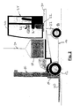
- Fig. 2 it is shown how with the aid of a hoist 36 Battery 38 is lifted out of the receiving space or lowered into it.
- the cover 34 is guided on the base body by means of suitable guides, for example with the help of U-rails on the base body, which with rollers on the Cover 34 cooperate (not shown).
- the relative movement between the vehicle body 10 and cover 34 can be unlocked with the help of locks, not shown be prevented.
- With a suitable execution of the guide it is possible to manually move the cover plus cabin 24 without additional drive.
- the position of the cover 34 can be opposite the base body 10 by a corresponding sensor or switch (not shown).
- the sensor signal is sent to the drive control of the vehicle given, so that dangerous situations for the operation of the vehicle are avoided become. For example, driving the vehicle at partial or completely open cover 34 can be prevented.
- the cover 34 may be part of the vehicle counterweight included and moved with a separate drive so that the Total center of gravity of the vehicle is shifted by moving the cover 34. This improves the stability of the counterbalance truck in the vehicle's longitudinal direction. By combining this shift with a maximum allowable Driving speed, safe operation of the vehicle is possible.
- the embodiment described last has a particularly advantageous effect.
- a heavy load is to be raised very high, as shown in FIG. 3 is.
- the driver positions the vehicle in front of you, for example Shelf and places the tiltable mast 16 vertically. Then he starts with the Lifting movement.
- the suitable displacement drive a displacement of the cover 34 including the Cabin 24 towards the rear of the vehicle.
- the cover 34 is in accordance with these sensor signals up to its rear end position.
- the one required for this Space also results from the space for e.g. Quadricycles necessary working aisle width.
- the rear of the lid is provided with a sensor 40, which detects obstacles that hinder the pushing movement or people and the movement stops automatically when danger is imminent.
- a sensor 40 which detects obstacles that hinder the pushing movement or people and the movement stops automatically when danger is imminent.
- the Movement of the cover 34 is stopped as soon as a hazard to people and things or the stability of the vehicle is to be feared.
- the vehicle For stacking the load on the shelf according to FIG. 3, the vehicle can be moved to the rear sliding cover can only be moved at reduced speed.
Landscapes
- Engineering & Computer Science (AREA)
- Transportation (AREA)
- Structural Engineering (AREA)
- Mechanical Engineering (AREA)
- Life Sciences & Earth Sciences (AREA)
- Geology (AREA)
- Civil Engineering (AREA)
- Power Engineering (AREA)
- Sustainable Energy (AREA)
- Sustainable Development (AREA)
- Chemical & Material Sciences (AREA)
- Combustion & Propulsion (AREA)
- Forklifts And Lifting Vehicles (AREA)
- Arrangement Or Mounting Of Propulsion Units For Vehicles (AREA)
Abstract
Description
- Fig. 1
- zeigt schematisch in Seitenansicht ein Flurförderzeug nach der Erfindung.
- Fig. 2
- zeigt eine Darstellung des Flurförderzeugs nach Fig. 1 während eines Batteriewechsels.
- Fig. 3
- zeigt das Flurförderzeug nach den Figuren 1 und 2 beim Anheben einer Last in großer Hubhöhe.
Claims (9)
- Batterie-elektrisch betriebenes Flurförderzeug, insbesondere Gegengewichtsstapler, mit einem Grundkörper mit vorderer Lastachse und hinterer Lenkachse, einem am Grundkörper angebrachten Hubgerüst für ein am Hubgerüst höhenverstellbares Lastmittel und einer Fahrerplatzanordnung auf dem Grundkörper mit Fahrersitz, Lenkmitteln und Bedienelementen, dadurch gekennzeichnet, dass der Grundkörper (10) einen nach oben offenen Aufnahmeraum für die Batterie (38) aufweist und die Fahrerplatzanordnung (24) auf einer deckelartigen Abdeckung (34) angeordnet ist, die annähernd horizontal verschiebbar an der Oberseite des Grundkörpers (10) geführt ist zur wahlweisen Freigabe des Aufnahmeraums.
- Flurförderzeug nach Anspruch 1, dadurch gekennzeichnet, dass die Abdeckung (34) seitlich mit Rollen oder Schienen versehen ist, die mit Schienen oder Rollen des Grundkörpers (10) zusammenwirken.
- Flurförderzeug nach Anspruch 1 oder 2, dadurch gekennzeichnet, dass zwischen der Abdeckung (34) und dem Grundkörper (10) entsperrbare Verriegelungsmittel wirken, die die Abdeckung in den Endstellungen verriegeln.
- Flurförderzeug nach einem der Ansprüche 1 bis 3, dadurch gekennzeichnet, dass eine Antriebsvorrichtung für die Abdeckung (34) vorgesehen ist.
- Flurförderzeug nach Anspruch 4, dadurch gekennzeichnet, dass Sensoren für das Lastgewicht und/oder die Lastschwerpunktslage und/oder die Hubgerüstneigung und/oder die Hubhöhe des Lastmittels (18, 20) vorgesehen sind und eine Steuervorrichtung für die Antriebsvorrichtung die Lage der Abdeckung (34) in Abhängigkeit von mindestens einem der Sensorsignale steuert.
- Flurförderzeug nach einem der Ansprüche 1 bis 5, dadurch gekennzeichnet, dass der Abdeckung (34) ein Positionssensor zugeordnet ist, welcher die Lage in mindestens einer Position erfasst und das Signal des Positionssensors auf eine Steuervorrichtung für den Antrieb des Flurförderzeugs gegeben wird.
- Flurförderzeug nach Anspruch 5 oder 6, dadurch gekennzeichnet, dass die Abdeckung (34) am hinteren Ende zumindest einen Teil des Gegengewichts aufnimmt.
- Flurförderzeug nach einem der Ansprüche 5 bis 7, dadurch gekennzeichnet, dass an der Rückseite der Abdeckung (34) mindestens ein Sensor (40) angeordnet ist, der ein Signal auf die Steuervorrichtung für den Abdeckungsantrieb gibt zwecks automatischer Unterbrechung der Bewegung der Abdeckung (34) bei einem vom Sensor (40) erfassten Hindernis.
- Flurförderzeug nach einem der Ansprüche 1 bis 8, dadurch gekennzeichnet, dass die Fahrerplatzanordnung eine Fahrerkabine (24) aufweist und die Fahrerkabine (24) drehbar auf der Abdeckung (34) angeordnet ist.
Applications Claiming Priority (2)
| Application Number | Priority Date | Filing Date | Title |
|---|---|---|---|
| DE10114571A DE10114571A1 (de) | 2001-03-24 | 2001-03-24 | Batterie-elektrisch betriebenes Flurförderzeug, insbesondere Gegengewichtsstapler |
| DE10114571 | 2001-03-24 |
Publications (2)
| Publication Number | Publication Date |
|---|---|
| EP1243490A1 true EP1243490A1 (de) | 2002-09-25 |
| EP1243490B1 EP1243490B1 (de) | 2003-07-30 |
Family
ID=7678916
Family Applications (1)
| Application Number | Title | Priority Date | Filing Date |
|---|---|---|---|
| EP02005087A Expired - Lifetime EP1243490B1 (de) | 2001-03-24 | 2002-03-07 | Batterie-elektrisch betriebenes Flurförderzeug, insbesondere Gegengewichtsstapler |
Country Status (3)
| Country | Link |
|---|---|
| US (1) | US6736587B2 (de) |
| EP (1) | EP1243490B1 (de) |
| DE (2) | DE10114571A1 (de) |
Cited By (3)
| Publication number | Priority date | Publication date | Assignee | Title |
|---|---|---|---|---|
| DE10317617A1 (de) * | 2003-04-16 | 2004-11-18 | Zf Friedrichshafen Ag | Batterie-elektrisch betriebenes Flurförderfahrzeug |
| DE102007004481A1 (de) * | 2007-01-30 | 2008-07-31 | Jungheinrich Ag | Flurförderzeug für den Mitfahrbetrieb |
| DE102011100918A1 (de) * | 2011-04-29 | 2012-10-31 | Jungheinrich Aktiengesellschaft | Flugförderzeug mit einer Fahrerkabine |
Families Citing this family (7)
| Publication number | Priority date | Publication date | Assignee | Title |
|---|---|---|---|---|
| DE10145991B4 (de) * | 2001-09-18 | 2021-02-11 | Linde Material Handling Gmbh | Rahmen für ein batteriebetriebenes Flurförderzeug |
| DE102006017889A1 (de) * | 2006-04-13 | 2007-10-25 | Linde Material Handling Gmbh | Flurförderzeug mit einer Batterie und Verfahren zum Betrieb eines Flurförderzeugs mit einer Batterie |
| WO2014068609A1 (ja) * | 2012-10-30 | 2014-05-08 | 川崎重工業株式会社 | 電動車両および電動車両用バッテリの搬出方法 |
| DE102013002554A1 (de) * | 2013-02-15 | 2014-08-21 | Jungheinrich Aktiengesellschaft | Verfahren zur Erkennung von Objekten in einem Lager und/oder zur räumlichen Orientierung in einem Lager |
| BR112017003874A2 (pt) | 2014-09-15 | 2018-01-23 | Crown Equip Corp | empilhadeira. |
| JP7456358B2 (ja) * | 2020-11-17 | 2024-03-27 | 株式会社豊田自動織機 | 産業車両 |
| CN119160827B (zh) * | 2024-09-30 | 2026-02-06 | 徐州徐工特种工程机械有限公司 | 一种新型平衡重叉车 |
Citations (5)
| Publication number | Priority date | Publication date | Assignee | Title |
|---|---|---|---|---|
| US2916172A (en) * | 1958-06-13 | 1959-12-08 | Burton H Locke | Fork lift truck with shiftable ballast |
| FR2137908A1 (de) * | 1971-05-13 | 1972-12-29 | Huta Stalowa Wola | |
| DE3020807A1 (de) * | 1979-06-02 | 1980-12-18 | Coventry Climax Ltd | Industrie-nutzfahrzeug |
| US4312418A (en) * | 1980-03-31 | 1982-01-26 | Clark Equipment Company | Pivoted valve and hood for lift truck |
| DE4321768A1 (de) * | 1993-06-30 | 1995-01-12 | Linde Ag | Flurförderzeug |
Family Cites Families (7)
| Publication number | Priority date | Publication date | Assignee | Title |
|---|---|---|---|---|
| US3275092A (en) * | 1964-05-05 | 1966-09-27 | Allis Chalmers Mfg Co | Electric truck battery compartment |
| DE7306935U (de) | 1973-02-23 | 1976-08-19 | O & K Orenstein & Koppel Ag, 1000 Berlin | Elektrische steckkontakteinrichtung fuer hubstapler |
| US4074785A (en) * | 1976-04-05 | 1978-02-21 | Towmotor Corporation | Battery enclosure |
| DE8715557U1 (de) * | 1987-11-24 | 1988-01-21 | Jungheinrich Unternehmensverwaltung Kg, 2000 Hamburg | Führungsvorrichtung für ein Batteriekabel in einem Flurförderzeug |
| GB2331054B (en) * | 1997-11-06 | 2001-08-08 | Lansing Linde Ltd | Industrial truck with a battery block |
| DE19815121A1 (de) | 1998-04-03 | 1999-10-07 | Still Gmbh | Stapler mit Gegengewicht |
| DE29918831U1 (de) * | 1999-10-26 | 2000-02-24 | Linde Ag, 65189 Wiesbaden | Flurförderzeug mit einem Batterieblock |
-
2001
- 2001-03-24 DE DE10114571A patent/DE10114571A1/de not_active Withdrawn
-
2002
- 2002-03-07 EP EP02005087A patent/EP1243490B1/de not_active Expired - Lifetime
- 2002-03-07 DE DE50200024T patent/DE50200024D1/de not_active Expired - Lifetime
- 2002-03-22 US US10/104,168 patent/US6736587B2/en not_active Expired - Fee Related
Patent Citations (5)
| Publication number | Priority date | Publication date | Assignee | Title |
|---|---|---|---|---|
| US2916172A (en) * | 1958-06-13 | 1959-12-08 | Burton H Locke | Fork lift truck with shiftable ballast |
| FR2137908A1 (de) * | 1971-05-13 | 1972-12-29 | Huta Stalowa Wola | |
| DE3020807A1 (de) * | 1979-06-02 | 1980-12-18 | Coventry Climax Ltd | Industrie-nutzfahrzeug |
| US4312418A (en) * | 1980-03-31 | 1982-01-26 | Clark Equipment Company | Pivoted valve and hood for lift truck |
| DE4321768A1 (de) * | 1993-06-30 | 1995-01-12 | Linde Ag | Flurförderzeug |
Cited By (4)
| Publication number | Priority date | Publication date | Assignee | Title |
|---|---|---|---|---|
| DE10317617A1 (de) * | 2003-04-16 | 2004-11-18 | Zf Friedrichshafen Ag | Batterie-elektrisch betriebenes Flurförderfahrzeug |
| DE102007004481A1 (de) * | 2007-01-30 | 2008-07-31 | Jungheinrich Ag | Flurförderzeug für den Mitfahrbetrieb |
| DE102011100918A1 (de) * | 2011-04-29 | 2012-10-31 | Jungheinrich Aktiengesellschaft | Flugförderzeug mit einer Fahrerkabine |
| DE102011100918A8 (de) * | 2011-04-29 | 2013-01-03 | Jungheinrich Aktiengesellschaft | Flurförderzeug mit einer Fahrerkabine |
Also Published As
| Publication number | Publication date |
|---|---|
| DE10114571A1 (de) | 2002-09-26 |
| US6736587B2 (en) | 2004-05-18 |
| EP1243490B1 (de) | 2003-07-30 |
| DE50200024D1 (de) | 2003-09-04 |
| US20020134599A1 (en) | 2002-09-26 |
Similar Documents
| Publication | Publication Date | Title |
|---|---|---|
| DE102020000820B4 (de) | Gabelstapler | |
| DE69800866T2 (de) | Transportabler Gabelhubwagen mit teleskopischem Hebearm | |
| EP0466065B1 (de) | Lastförderfahrzeug | |
| DE10305900C5 (de) | Stapler | |
| DE29723095U1 (de) | Flurförderfahrzeug | |
| EP1243490B1 (de) | Batterie-elektrisch betriebenes Flurförderzeug, insbesondere Gegengewichtsstapler | |
| DE69806316T2 (de) | Wagen mit Hubmast, geeignet zur Montage an das Ende eines Transportfahrzeugs | |
| DE19518116A1 (de) | Flurförderzeug mit einem Fahrerstand | |
| DE3017456A1 (de) | Hochregalstapler | |
| EP0465838B1 (de) | Lastaufnahmefahrzeug mit Kippsicherung | |
| EP1447376B1 (de) | Schubmaststapler | |
| DE69501578T3 (de) | Motorhubwagen mit teleskopischem Arm | |
| DE602004001836T2 (de) | Transportabler Gabelhubwagen | |
| EP2511224B1 (de) | Hochregalflurförderzeug, insbesondere Kommissionierflurförderzeug, mit einem Fahrersitz und seitlichen Armlehnen | |
| DE2739325A1 (de) | Verladefahrzeug | |
| DE69734731T2 (de) | Fahrzeug zum personentransport | |
| EP1447373B1 (de) | Verfahren zum Betrieb eines Schubmaststaplers und Schubmaststapler zur Durchführung des Verfahrens | |
| EP0983899B1 (de) | Ladevorrichtung zum Be- und Entladen eines Fahrzeuges | |
| DE3117803C2 (de) | Hochregalstapler | |
| DE4331832C2 (de) | Ladegerät | |
| EP1179466B1 (de) | Flurförderzeug mit einer Lastaufnahmevorrichtung | |
| EP0583546A1 (de) | Flurförderzeug, insbesondere fahrerloses Fahrzeug | |
| DE19830373B4 (de) | Lastenhandhabungsfahrzeug | |
| DE29922311U1 (de) | Stapler | |
| DE4440399A1 (de) | Gabelstapler |
Legal Events
| Date | Code | Title | Description |
|---|---|---|---|
| PUAI | Public reference made under article 153(3) epc to a published international application that has entered the european phase |
Free format text: ORIGINAL CODE: 0009012 |
|
| AK | Designated contracting states |
Kind code of ref document: A1 Designated state(s): AT BE CH CY DE DK ES FI FR GB GR IE IT LI LU MC NL PT SE TR |
|
| AX | Request for extension of the european patent |
Free format text: AL;LT;LV;MK;RO;SI |
|
| 17P | Request for examination filed |
Effective date: 20020824 |
|
| GRAH | Despatch of communication of intention to grant a patent |
Free format text: ORIGINAL CODE: EPIDOS IGRA |
|
| GRAH | Despatch of communication of intention to grant a patent |
Free format text: ORIGINAL CODE: EPIDOS IGRA |
|
| AKX | Designation fees paid |
Designated state(s): DE FR GB IT SE |
|
| GRAA | (expected) grant |
Free format text: ORIGINAL CODE: 0009210 |
|
| AK | Designated contracting states |
Designated state(s): DE FR GB IT SE |
|
| REG | Reference to a national code |
Ref country code: GB Ref legal event code: FG4D Free format text: NOT ENGLISH |
|
| REG | Reference to a national code |
Ref country code: IE Ref legal event code: FG4D Free format text: GERMAN |
|
| REF | Corresponds to: |
Ref document number: 50200024 Country of ref document: DE Date of ref document: 20030904 Kind code of ref document: P |
|
| GBT | Gb: translation of ep patent filed (gb section 77(6)(a)/1977) |
Effective date: 20031025 |
|
| REG | Reference to a national code |
Ref country code: SE Ref legal event code: TRGR |
|
| REG | Reference to a national code |
Ref country code: IE Ref legal event code: FD4D |
|
| ET | Fr: translation filed | ||
| PLBE | No opposition filed within time limit |
Free format text: ORIGINAL CODE: 0009261 |
|
| STAA | Information on the status of an ep patent application or granted ep patent |
Free format text: STATUS: NO OPPOSITION FILED WITHIN TIME LIMIT |
|
| 26N | No opposition filed |
Effective date: 20040504 |
|
| PGFP | Annual fee paid to national office [announced via postgrant information from national office to epo] |
Ref country code: SE Payment date: 20091222 Year of fee payment: 9 |
|
| PGFP | Annual fee paid to national office [announced via postgrant information from national office to epo] |
Ref country code: FR Payment date: 20100331 Year of fee payment: 9 |
|
| PGFP | Annual fee paid to national office [announced via postgrant information from national office to epo] |
Ref country code: IT Payment date: 20100327 Year of fee payment: 9 |
|
| REG | Reference to a national code |
Ref country code: SE Ref legal event code: EUG |
|
| REG | Reference to a national code |
Ref country code: FR Ref legal event code: ST Effective date: 20111130 |
|
| PG25 | Lapsed in a contracting state [announced via postgrant information from national office to epo] |
Ref country code: FR Free format text: LAPSE BECAUSE OF NON-PAYMENT OF DUE FEES Effective date: 20110331 |
|
| PG25 | Lapsed in a contracting state [announced via postgrant information from national office to epo] |
Ref country code: IT Free format text: LAPSE BECAUSE OF NON-PAYMENT OF DUE FEES Effective date: 20110307 |
|
| PGFP | Annual fee paid to national office [announced via postgrant information from national office to epo] |
Ref country code: GB Payment date: 20120322 Year of fee payment: 11 |
|
| PG25 | Lapsed in a contracting state [announced via postgrant information from national office to epo] |
Ref country code: SE Free format text: LAPSE BECAUSE OF NON-PAYMENT OF DUE FEES Effective date: 20110308 |
|
| GBPC | Gb: european patent ceased through non-payment of renewal fee |
Effective date: 20130307 |
|
| PG25 | Lapsed in a contracting state [announced via postgrant information from national office to epo] |
Ref country code: GB Free format text: LAPSE BECAUSE OF NON-PAYMENT OF DUE FEES Effective date: 20130307 |
|
| PGFP | Annual fee paid to national office [announced via postgrant information from national office to epo] |
Ref country code: DE Payment date: 20150601 Year of fee payment: 14 |
|
| REG | Reference to a national code |
Ref country code: DE Ref legal event code: R119 Ref document number: 50200024 Country of ref document: DE |
|
| PG25 | Lapsed in a contracting state [announced via postgrant information from national office to epo] |
Ref country code: DE Free format text: LAPSE BECAUSE OF NON-PAYMENT OF DUE FEES Effective date: 20161001 |