EP1243461A1 - Sitzuntergestell für einen Fahrzeugsitz - Google Patents
Sitzuntergestell für einen Fahrzeugsitz Download PDFInfo
- Publication number
- EP1243461A1 EP1243461A1 EP02090055A EP02090055A EP1243461A1 EP 1243461 A1 EP1243461 A1 EP 1243461A1 EP 02090055 A EP02090055 A EP 02090055A EP 02090055 A EP02090055 A EP 02090055A EP 1243461 A1 EP1243461 A1 EP 1243461A1
- Authority
- EP
- European Patent Office
- Prior art keywords
- seat
- adjustment
- side parts
- base frame
- frame according
- Prior art date
- Legal status (The legal status is an assumption and is not a legal conclusion. Google has not performed a legal analysis and makes no representation as to the accuracy of the status listed.)
- Granted
Links
Images




Classifications
-
- B—PERFORMING OPERATIONS; TRANSPORTING
- B60—VEHICLES IN GENERAL
- B60N—SEATS SPECIALLY ADAPTED FOR VEHICLES; VEHICLE PASSENGER ACCOMMODATION NOT OTHERWISE PROVIDED FOR
- B60N2/00—Seats specially adapted for vehicles; Arrangement or mounting of seats in vehicles
- B60N2/02—Seats specially adapted for vehicles; Arrangement or mounting of seats in vehicles the seat or part thereof being movable, e.g. adjustable
- B60N2/04—Seats specially adapted for vehicles; Arrangement or mounting of seats in vehicles the seat or part thereof being movable, e.g. adjustable the whole seat being movable
- B60N2/16—Seats specially adapted for vehicles; Arrangement or mounting of seats in vehicles the seat or part thereof being movable, e.g. adjustable the whole seat being movable height-adjustable
- B60N2/18—Seats specially adapted for vehicles; Arrangement or mounting of seats in vehicles the seat or part thereof being movable, e.g. adjustable the whole seat being movable height-adjustable the front or the rear portion of the seat being adjustable, e.g. independently of each other
- B60N2/185—Seats specially adapted for vehicles; Arrangement or mounting of seats in vehicles the seat or part thereof being movable, e.g. adjustable the whole seat being movable height-adjustable the front or the rear portion of the seat being adjustable, e.g. independently of each other characterised by the drive mechanism
- B60N2/1853—Linear actuator, e.g. screw mechanism
-
- B—PERFORMING OPERATIONS; TRANSPORTING
- B60—VEHICLES IN GENERAL
- B60N—SEATS SPECIALLY ADAPTED FOR VEHICLES; VEHICLE PASSENGER ACCOMMODATION NOT OTHERWISE PROVIDED FOR
- B60N2/00—Seats specially adapted for vehicles; Arrangement or mounting of seats in vehicles
- B60N2/02—Seats specially adapted for vehicles; Arrangement or mounting of seats in vehicles the seat or part thereof being movable, e.g. adjustable
- B60N2/04—Seats specially adapted for vehicles; Arrangement or mounting of seats in vehicles the seat or part thereof being movable, e.g. adjustable the whole seat being movable
- B60N2/06—Seats specially adapted for vehicles; Arrangement or mounting of seats in vehicles the seat or part thereof being movable, e.g. adjustable the whole seat being movable slidable
- B60N2/067—Seats specially adapted for vehicles; Arrangement or mounting of seats in vehicles the seat or part thereof being movable, e.g. adjustable the whole seat being movable slidable by linear actuators, e.g. linear screw mechanisms
-
- B—PERFORMING OPERATIONS; TRANSPORTING
- B60—VEHICLES IN GENERAL
- B60N—SEATS SPECIALLY ADAPTED FOR VEHICLES; VEHICLE PASSENGER ACCOMMODATION NOT OTHERWISE PROVIDED FOR
- B60N2/00—Seats specially adapted for vehicles; Arrangement or mounting of seats in vehicles
- B60N2/02—Seats specially adapted for vehicles; Arrangement or mounting of seats in vehicles the seat or part thereof being movable, e.g. adjustable
- B60N2/04—Seats specially adapted for vehicles; Arrangement or mounting of seats in vehicles the seat or part thereof being movable, e.g. adjustable the whole seat being movable
- B60N2/16—Seats specially adapted for vehicles; Arrangement or mounting of seats in vehicles the seat or part thereof being movable, e.g. adjustable the whole seat being movable height-adjustable
- B60N2/1605—Seats specially adapted for vehicles; Arrangement or mounting of seats in vehicles the seat or part thereof being movable, e.g. adjustable the whole seat being movable height-adjustable characterised by the cinematic
- B60N2/161—Rods
- B60N2/1615—Parallelogram-like structure
-
- B—PERFORMING OPERATIONS; TRANSPORTING
- B60—VEHICLES IN GENERAL
- B60N—SEATS SPECIALLY ADAPTED FOR VEHICLES; VEHICLE PASSENGER ACCOMMODATION NOT OTHERWISE PROVIDED FOR
- B60N2/00—Seats specially adapted for vehicles; Arrangement or mounting of seats in vehicles
- B60N2/02—Seats specially adapted for vehicles; Arrangement or mounting of seats in vehicles the seat or part thereof being movable, e.g. adjustable
- B60N2/04—Seats specially adapted for vehicles; Arrangement or mounting of seats in vehicles the seat or part thereof being movable, e.g. adjustable the whole seat being movable
- B60N2/16—Seats specially adapted for vehicles; Arrangement or mounting of seats in vehicles the seat or part thereof being movable, e.g. adjustable the whole seat being movable height-adjustable
- B60N2/1635—Seats specially adapted for vehicles; Arrangement or mounting of seats in vehicles the seat or part thereof being movable, e.g. adjustable the whole seat being movable height-adjustable characterised by the drive mechanism
- B60N2/164—Linear actuator, e.g. screw mechanism
-
- B—PERFORMING OPERATIONS; TRANSPORTING
- B60—VEHICLES IN GENERAL
- B60N—SEATS SPECIALLY ADAPTED FOR VEHICLES; VEHICLE PASSENGER ACCOMMODATION NOT OTHERWISE PROVIDED FOR
- B60N2/00—Seats specially adapted for vehicles; Arrangement or mounting of seats in vehicles
- B60N2/02—Seats specially adapted for vehicles; Arrangement or mounting of seats in vehicles the seat or part thereof being movable, e.g. adjustable
- B60N2/04—Seats specially adapted for vehicles; Arrangement or mounting of seats in vehicles the seat or part thereof being movable, e.g. adjustable the whole seat being movable
- B60N2/16—Seats specially adapted for vehicles; Arrangement or mounting of seats in vehicles the seat or part thereof being movable, e.g. adjustable the whole seat being movable height-adjustable
- B60N2/18—Seats specially adapted for vehicles; Arrangement or mounting of seats in vehicles the seat or part thereof being movable, e.g. adjustable the whole seat being movable height-adjustable the front or the rear portion of the seat being adjustable, e.g. independently of each other
- B60N2/1803—Seats specially adapted for vehicles; Arrangement or mounting of seats in vehicles the seat or part thereof being movable, e.g. adjustable the whole seat being movable height-adjustable the front or the rear portion of the seat being adjustable, e.g. independently of each other with independent front and/or rear adjustment
-
- B—PERFORMING OPERATIONS; TRANSPORTING
- B60—VEHICLES IN GENERAL
- B60N—SEATS SPECIALLY ADAPTED FOR VEHICLES; VEHICLE PASSENGER ACCOMMODATION NOT OTHERWISE PROVIDED FOR
- B60N2/00—Seats specially adapted for vehicles; Arrangement or mounting of seats in vehicles
- B60N2/02—Seats specially adapted for vehicles; Arrangement or mounting of seats in vehicles the seat or part thereof being movable, e.g. adjustable
- B60N2/04—Seats specially adapted for vehicles; Arrangement or mounting of seats in vehicles the seat or part thereof being movable, e.g. adjustable the whole seat being movable
- B60N2/16—Seats specially adapted for vehicles; Arrangement or mounting of seats in vehicles the seat or part thereof being movable, e.g. adjustable the whole seat being movable height-adjustable
- B60N2/18—Seats specially adapted for vehicles; Arrangement or mounting of seats in vehicles the seat or part thereof being movable, e.g. adjustable the whole seat being movable height-adjustable the front or the rear portion of the seat being adjustable, e.g. independently of each other
- B60N2/1807—Seats specially adapted for vehicles; Arrangement or mounting of seats in vehicles the seat or part thereof being movable, e.g. adjustable the whole seat being movable height-adjustable the front or the rear portion of the seat being adjustable, e.g. independently of each other characterised by the cinematic
- B60N2/181—Rods
Definitions
- the invention relates to a seat base for a vehicle seat according to the preamble of the claim 1.
- a multiple setting known from DE 199 04 224 C1 of the seat height and seat inclination has a lower rail, a Top rail, an adjustment lever and a connecting lever that is hinged to the top of the top rail and is pivotally mounted on the same axes is like the adjustment lever.
- a device known from EP 0 813 990 A2 translational adjustment of a seat part, in particular for longitudinal seat cushion adjustment and motor vehicle seats, has a leadership backdrop, one in the leadership backdrop guided support element and one between the edge of the Guide link and the slider mounted on the support element on.
- a seat base frame known from DE 199 22 993 A1 for a motor vehicle seat has a movable seat frame on the two long sides over one each front and a rear adjustment lever with a vehicle floor side Assembly is articulated and one Adjustment device for the inclination of the seat cushion holder has, which comprises a spindle gear which with one of the Moving adjustment lever for adjusting the seat height connected is.
- DE 199 04 224 C1 is an adjustable one Seat underframe for a vehicle seat with a longitudinal rail guide known, the one attachable to the vehicle floor Bottom rail and sliding on the bottom rail Top rail and a device for adjusting the Seat height and / or seat inclination with an adjustment lever comprises, which is arranged laterally next to the rail longitudinal guide and on one axis on the one hand with the top rail and on the other hand articulated to the seat support is.
- DE 199 06 621 A1 describes a multi adjustment a drive for a vehicle seat with a height and reclining seat pan known in the front and rear area on trestles with oppositely inclined Control scenes is mounted, the trestles slidable store on a seat rail.
- the object of the present invention is to provide a seat base for a vehicle seat of the aforementioned Type the seat depth and seat tilt adjustment together to combine that an optimal force application point using a minimal number of power transmission elements with optimal leadership characteristics at the same time is guaranteed.
- the solution according to the invention creates a combination for a seat depth and seat inclination adjustment with optimal Force application point for both seat adjustments and enables a significant reduction in parts for power transmission from the adjustment drive to the force application point on the seat part.
- the solution according to the invention is based on the idea independently of each other a horizontal and vertical Movement of the seat pan by means of two intersecting ones Realize slide guides through which a universal joint axis which engages both the seat depth adjustment as well also causes the seat tilt adjustment.
- the guide links are preferably designed as an elongated hole and in the seat side parts and seat pan mounts aligned essentially perpendicular to each other arranged.
- the runs in the seat side parts arranged guide link essentially perpendicular to Longitudinal extension of the seat side parts and causes the guidance the universal joint axis for a seat inclination adjustment, while the one essentially perpendicular to it Guiding backdrop in the seat pan mounts, which are fixed with the seat pan are connected, the seat depth adjustment serve.
- the universal joint axis consists in particular of three a bore provided sliding elements and one through the Bore the sliding elements and the guide slots Threaded bolt that has a lever arrangement with both the drive device for seat depth adjustment as well with the drive device for seat inclination adjustment connected is.
- the two outer ones are of the three-part glider system Glides in the guide linkages of the seat side parts and the Sliding seat holder arranged.
- the middle glider serves to support the seat depth and seat inclination adjustment between the guide slots of the seat side parts and the seat pan holder.
- the outer gliders point a hollow cylindrical shaft that fits into the respective Leadership setting is inserted, continue to point out Gliders on the side, protruding from the head of the glider elements Bridges on the side boundaries of the respective Leadership backdrops.
- the bridges and the shafts are used to guide the seat incline and seat depth adjustment and should limit the play of the adjustment device and improve the friction properties.
- the middle gliding element of the three-part gliding system serves to support the seat depth and seat inclination adjustment and has lateral webs that are farther apart are spaced apart as the width of the slots Guide scenes with web-shaped side boundaries are provided so that tilting movements of the adjusting device be limited.
- resilient tongues of the middle slider will eliminates axial play of the universal joint axis since the middle Sliding element with the resilient tongues against the to Guide scenes adjacent surfaces of the seat side parts and the seat pan receptacles presses.
- connection of the universal joint axis with the two Drive devices for seat depth and seat angle adjustment takes place via an adjustment lever which is connected to a Spindle drive for both the seat depth and for the Seat tilt adjustment is connected.
- the spindle drive for seat depth adjustment is via a swivel and a Traverse connected to the adjustment lever.
- the spindle drive for the seat tilt adjustment is about a first Rotary lever with one connecting the two universal joint axes Adjusting tube and a second rotary lever with the adjusting lever connected.
- the adjustment lever has a first linkage for receiving of the threaded bolt of the universal joint axis, a middle shot for the articulation of the traverse and a third mount for articulating the second rotary lever of the spindle drive to adjust the seat inclination.
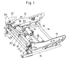
- Figure 1 shows a perspective view of a seat base of a vehicle seat on its two long sides with one top rail each of a longitudinal rail guide 15, 16 is connected, which consists of the top rails and the there is a bottom rail connected to the vehicle floor, which interlocking in a longitudinally displaceable manner.
- the seat base consists of two seat side parts 11, 12 which at their front and rear ends via cross struts 13, 14 connected to form a seat frame are.
- a Adjustment motor 17 is provided, the drive axis via a Gear engages in the rail longitudinal guide 15, 16.
- to Seat height adjustment serves a lever arrangement 18, which from the seat side parts 11, 12 and the cross struts 13, 14 existing seat frame in relation to the vehicle floor raises or lowers.
- a seat pan (seat cushion support) 25 is on two next to the Seat side parts 11, 12 arranged seat pan receptacles 21, 22 and on a seat pan attachment 23, by one Drive motor 80 of a drive device 8 for seat depth adjustment is flanged, attached.
- the as a spindle drive trained drive device for seat depth adjustment 8 has a spindle 81 in addition to the drive motor 80 as well as a swivel joint 82 and a cross member 83 and causes a displacement of the seat pan 25 in the direction of Double arrow SN relative to the seat frame.
- drive device for seat inclination adjustment 9 a drive motor 90 and causes a raising or lowering the front edge of the seat pan 25 corresponding to the Double arrow SN and thus a rotary movement around a fictitious one Pivot point.
- the in the area of the leading edges of the Seat side parts 11, 12 and the seat pan receptacles 21, 22 arranged combined adjustment device for adjustment the seat depth and seat inclination is subsequently based on the Figures 2 to 5 and on the basis of individual parts in Figures 6 to 16 explained in more detail.
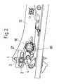
- FIG. 2 shows a side view of one of the two adjustment devices, on the right side of the seat in the direction of travel 12 of the vehicle seat is arranged.
- the adjustment device comprises two intersecting scenes 1, 2, which are designed as an elongated hole and of which the first Guide link 1 substantially perpendicular to the longitudinal extent of the seat side part 12 at the front end of the Seat side part 12 and the second guide link 2 in Essentially perpendicular to the first guide link 1 in the right seat pan receptacle 22 is arranged.
- Both yourself intersecting guide links 1, 2 are on a universal joint axis 3 connected to each other on which the two drive devices for seat depth and seat angle adjustment attack. How this is done in detail is the perspective representations of the adjusting device according to Figures 3 and 4 and the exploded view according to FIG. 5.
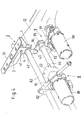
- Figure 3 shows a perspective view of the direction of travel left, arranged on the left seat side part 11 Adjustment device, as well as the right seat side part 12 essentially designed as an elongated hole perpendicular to the longitudinal extent of the seat side part 11 extending guide link 1.
- Perpendicular to the first guide link 1 extends in the left Seat pan receptacle 21 arranged and also as an elongated hole trained second guide link 2, which is thus essentially in the longitudinal adjustment direction of the vehicle seat extends.
- the two leadership scenes 1, 2 penetrating Universal joint axis 3 is connected to an adjusting lever 4, on which with the drive device for seat depth adjustment 8 connected according to Figure 1 cross member 83 and Rotary lever 92, 94 and an adjusting tube 93 the drive device for seat inclination adjustment 9 according to FIG. 4.
- the combined seat depth and seat tilt adjustment causing universal joint axis 3 penetrates the two vertically mutually standing guide links 1, 2, of which the first guide link 1 perpendicular to the longitudinal extent the seat side parts 11, 12 arranged at the front end and as an elongated hole with an inward facing Side boundary 10 is provided.
- second guide link 2 is located in the two seat pan receptacles 21, 22 and is also designed as an elongated hole, which is essentially extends perpendicular to the first guide link 1 and one facing the inner surfaces of the seat side parts 11, 12, protruding from the side surface of the seat pan receptacles 22 Has side boundary 20 according to Figure 6.
- the Universal joint axis 3 consists of three sliding elements 4, 5, 6, which have aligned holes 40, 50, 60, through which a threaded bolt 30 according to Figures 5, 15 and 16 is inserted.
- the universal joint axis 3 is with a Adjusting lever 4 connected to an upper receptacle 41 Inclusion of the threaded end of the threaded bolt, a middle receptacle 42 for connection to the Traverse 83 and a lower receptacle 43 for connection with a second rotary lever 94 of the drive device for Has seat tilt adjustment 9.
- sliding elements 4, 5, 6 are the two outer ones Sliding elements 4, 6 are substantially identical in construction and have a hollow cylindrical shaft 40, 60, from which the one shaft 40 in the first guide link 1 and the other shaft 61 in the second guide link 2 is slidable in the longitudinal direction so that the heads 42, 62 of the outer sliding elements 4, 6 on the outer surfaces the seat side parts 11, 12 or the inward Surfaces of the seat pan receptacles 21, 22 abut.
- the middle sliding element is between the guide links 1, 2 5 arranged that with outer webs on the side boundaries 10, 20 of the guide link 1, 2 and thus limiting tipping movements.
- the adjusting tube 93 of the drive device for seat inclination adjustment 9 is on a bore 95 in the seat side parts 11, 12 by means of second threaded bolts 97 and over Bearing bushes 96 and a hole in a second rotary lever 94 attached and with a first rotary lever 92 a spindle 91 connected by a drive motor 90 is adjusted for seat inclination.
- the cross arm 83 is connected via a swivel joint 82 to a spindle 81 connected, which together with the drive motor 80 Forms drive device for seat depth adjustment 8.
- the drive motor 80 in the one or the other direction of rotation and thus the Spindle 81 lengthened or shortened, so that the position of the Drive motor 80 and thus the location of the drive motor 80 connected tray attachment 23 with respect to the Traverse 83 is changed.
- the swivel joint 82 serves an angle compensation for the position adjustment. Since the Traverse 83 over the universal joint axis 3 and the first Link guide 1 in the seat side parts 11, 12 in the longitudinal direction is set, causes a change in length of the Spindle 81 on the seat pan attachment 23 and the side Seat pan recordings 21, 22 a shift of Seat pan receptacles 21, 22 over the length of the second Guide slots 2 in relation to the seat side parts 11, 12.
- FIGS Universal joint axes
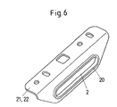
- Figure 6 shows a perspective view of the seat pan receptacles 21, 22, which are designed as an angle and at their Side surfaces the second guide slot designed as an elongated hole 2 with a side boundary protruding from the side surface 20 have.
- the seat pan mounts are on the surface 21, 22 with holes for fixing the tub Mistake.
- outer sliding elements 4, 6 5 of which the one outer sliding element 6 of the Guide link 2 of the seat pan receptacles 21, 22 assigned is shown in Figures 7 to 9. They exist from a hollow cylindrical shaft 41, 61, the bore 40, 60 with the bore of the other outer sliding element 4, 6 and the hole in the middle sliding element is aligned and the reception of the threaded bolt 30. From the head 42, 62 of the outer sliding elements 4, 6 are lateral webs 43, 63 or 44, 64 and encompass the side boundaries 10, 20 the guide link 1, 2. The ends of the webs 43, 63 and 44, 64 are resilient and rest on the the side boundaries 10, 20 adjacent side surfaces the seat side parts 11, 12 or the seat pan receptacles 21, 22 on.
- the shaft 41, 61 is of arched webs 45, 65 and 46, 66 edged, the flush installation of the side boundaries 10, 20 between the side webs 43, 63 or 44, 64 and the webs 45, 65 and 46, 66 effect.
- the middle sliding element shown in Figures 10 to 12 5 points from the sliding element head 50 on both sides protruding slide bars 51 to 54, which around the side boundaries 10, 20 of the guide slots 1, 2 grip and thus Limit tilting movements of the universal joint axis 3.
- the middle sliding element 5 has resilient tongues 55, 56 on, which compensate for the axial play of the universal joint axis 3 and thus the outer sliding elements 4, 6 against the Side surfaces of the side parts 11, 12 and seat pan receptacles Press 21, 22.
- Figure 13 shows a perspective view and figure 14 in a side view the threaded bolt for connection of the three sliding elements 4, 5, 6, the shaft 32 through the aligned holes 40, 50, 60 of the sliding elements 4, 5, 6 is inserted and with its bolt head 31st on the outward-facing surfaces of the seat side parts 11, 12 abuts and with its threaded part 33 with the adjusting lever 4 is screwed.
Landscapes
- Engineering & Computer Science (AREA)
- Aviation & Aerospace Engineering (AREA)
- Transportation (AREA)
- Mechanical Engineering (AREA)
- Seats For Vehicles (AREA)
Abstract
Description
- Figur 1
- eine perspektivische Ansicht eines auf Schienenlängsführungen gelagerten Sitzuntergestells;
- Figur 2
- eine Seitenansicht eines Teils des Sitzuntergestells mit sich kreuzenden Kulissen zur Sitztiefen- und Sitzneigungsverstellung;
- Figur 3
- eine perspektivische Ansicht der sich kreuzenden Führungskulissen zur Sitzneigungs- und Sitztiefenverstellung;
- Figur 4
- eine perspektivische Ansicht der sich kreuzenden Führungskulissen mit den An-triebseinrichtungen zur Sitztiefen- und Sitzneigungsverstellung;
- Figur 5
- eine Explosionsdarstellung der Einzelteile der Kulissenführung zur Sitztiefen- und Sitzneigungsverstellung;
- Figur 6
- eine perspektivische Einzelansicht einer Sitzwannenaufnahme mit Führungskulisse;
- Fig. 7 - 9
- eine perspektivische Ansicht, Draufsicht und ein Schnitt durch ein äußeres Gleitelement;
- Fig. 10 - 12
- mehrere Ansichten und Schnitte durch das mittlere Gleitelement und
- Fig. 13 u. 14
- eine perspektivische Ansicht und Seitenansicht des Gewindebolzens der Kreuzgelenkachse.
Claims (11)
- Sitzuntergestell für einen Fahrzeugsitz, mit jeweils einem zwei Seitenteile aufweisenden Sitzrahmen, einer Sitzwanne zur Aufnahme eines Sitzkissens und einer Einrichtung zur Sitztiefen- und Sitzneigungsverstellung,
gekennzeichnet durch
eine jeweils in den Sitzseitenteilen (11, 12) angeordnete erste Führungskulisse (1),
eine jeweils in Sitzwannenaufnahmen (21, 22) angeordnete zweite Führungskulisse (2),
und eine Kreuzgelenkachse (3), die beide Führungskulissen (1, 2) durchgreift und mit einem Antrieb (8) zur Sitztiefenverstellung und einem Antrieb (9) zur Sitzneigungsverstellung verbunden ist. - Sitzuntergestell nach Anspruch 1, dadurch gekennzeichnet, dass die Führungskulissen (1, 2) als Langloch ausgebildet und im wesentlichen senkrecht zueinanderstehend ausgerichtet sind.
- Sitzuntergestell nach Anspruch 2, dadurch gekennzeichnet, dass die in den Sitzseitenteilen (11, 12) angeordneten Führungskulissen (1) im wesentlichen senkrecht zur Längserstreckung der Sitzseitenteile (11, 12) verlaufen.
- Sitzuntergestell nach mindestens einem der voranstehenden Ansprüche, dadurch gekennzeichnet, dass die Kreuzgelenkachse (3) aus drei mit einer Bohrung (40, 50, 60) versehenen Gleitelementen (4, 5, 6) und einem durch die Bohrungen (40, 50, 60) der Gleitelemente (4, 5, 6) und die Führungskulissen (1, 2) gesteckten Gewindebolzen (30) gebildet sind.
- Sitzuntergestell nach Anspruch 4, dadurch gekennzeichnet, dass äußere Gleitelemente (4, 6) zur Sitztiefenund Sitzneigungsverstellung in den Führungskulissen (1, 2) der Sitzseitenteile (11, 12) und der Sitzwannenaufnahmen (21, 22) gleitend angeordnet sind und dass ein mittleres Gleitelement (5) zur Abstützung der Sitztiefen- und Sitzneigungsverstellung zwischen den Führungskulissen (1, 2) der Sitzseitenteile (11, 12) und der Sitzwannenaufnahmen (21, 22) angeordnet ist.
- Sitzuntergestell nach Anspruch 5, dadurch gekennzeichnet, dass die äußeren Gleitelemente (4, 6) einen in die jeweilige Führungskulisse (1 bzw. 2) gesteckten hohlzylindrischen Schaft (41, 61) und seitliche, vom Kopf (42, 62) der äußeren Gleitelemente (4, 6) abstehende Stege (43, 44; 63, 64) aufweisen, die an Seitenbegrenzungen (10, 20) der Führungskulissen (1, 2) der Sitzseitenteile (11, 12) bzw. der Sitzwannenaufnahmen (21, 22) anliegen.
- Sitzuntergestell nach Anspruch 6, dadurch gekennzeichnet, dass die einander zugewandten Seitenbegrenzungen (10, 20) der Führungskulissen (1, 2) von den Seitenflächen der Sitzseitenteile (11, 12) und der Sitzwannenaufnahmen (21, 22) abstehen und dass das mittlere Gleitelement (5) die Seitenbegrenzungen (10, 20) der Führungskulissen (1, 2) umfassende Stege und an den Seitenflächen der Sitzseitenteile (11, 12) und der Sitzwannenaufnahmen (21, 22) anliegende, federnde Zungen aufweist.
- Sitzuntergestell nach mindestens einem der voranstehenden Ansprüche, dadurch gekennzeichnet, dass die Kreuzgelenkachse (3) über einen Verstellhebel (4) sowohl mit einem Spindelantrieb (80, 81) zur Sitztiefenverstellung (8) als auch mit einem Spindelantrieb (90, 91) zur Sitzneigungsverstellung (9) verbunden ist.
- Sitzuntergestell nach Anspruch 8, dadurch gekennzeichnet, dass der Spindelantrieb (80, 81) zur Sitztiefenverstellung (8) über ein Drehgelenk (82) und einer Traverse (83) mit dem Verstellhebel (4) verbunden ist.
- Sitzuntergestell nach Anspruch 8, dadurch gekennzeichnet, dass der Spindelantrieb (90, 91) zur Sitzneigungsverstellung (9) über einen ersten Drehhebel (92) mit einem die beidseitigen Kreuzgelenkachsen (3) verbindenden Verstellrohr (93) und über einen zweiten Drehhebel (94) mit dem Verstellhebel (4) verbunden ist.
- Sitzuntergestell nach Anspruch 10, dadurch gekennzeichnet, dass der Verstellhebel (4) eine erste Anlenkung zur Aufnahme des Gewindebolzens (30), eine mittlere Aufnahme (42) zur Anlenkung der Traverse (83) und eine dritte Aufnahme (43) zur Anlenkung des zweiten Drehhebels (94) zur Sitzneigungsverstellung (9) aufweist.
Applications Claiming Priority (2)
| Application Number | Priority Date | Filing Date | Title |
|---|---|---|---|
| DE2001113153 DE10113153C1 (de) | 2001-03-14 | 2001-03-14 | Sitzuntergestell für einen Fahrzeugsitz |
| DE10113153 | 2001-03-14 |
Publications (2)
| Publication Number | Publication Date |
|---|---|
| EP1243461A1 true EP1243461A1 (de) | 2002-09-25 |
| EP1243461B1 EP1243461B1 (de) | 2007-08-15 |
Family
ID=7678005
Family Applications (1)
| Application Number | Title | Priority Date | Filing Date |
|---|---|---|---|
| EP20020090055 Expired - Lifetime EP1243461B1 (de) | 2001-03-14 | 2002-02-13 | Sitzuntergestell für einen Fahrzeugsitz |
Country Status (3)
| Country | Link |
|---|---|
| EP (1) | EP1243461B1 (de) |
| DE (2) | DE10113153C1 (de) |
| ES (1) | ES2291419T3 (de) |
Cited By (4)
| Publication number | Priority date | Publication date | Assignee | Title |
|---|---|---|---|---|
| JP2007512169A (ja) * | 2003-11-28 | 2007-05-17 | ブローゼ・ファールツォイクタイレ・ゲーエムベーハー・ウント・コンパニ・コマンディットゲゼルシャフト・コーブルク | 自動車の、特に自動車用シートの、相対移動可能な二つのサブアセンブリをガイド方向にガイドする装置 |
| JP2009531231A (ja) * | 2006-03-27 | 2009-09-03 | ジョンソン コントロールズ テクノロジー カンパニー | シートアジャスタ用のトランスミッションデバイス |
| CN111216606A (zh) * | 2018-11-26 | 2020-06-02 | 现代自动车株式会社 | 车辆座椅的高度调节装置 |
| CN113492736A (zh) * | 2020-04-02 | 2021-10-12 | 现代自动车株式会社 | 一种用于车辆的放松舒适座椅 |
Families Citing this family (16)
| Publication number | Priority date | Publication date | Assignee | Title |
|---|---|---|---|---|
| DE10262266B4 (de) * | 2002-06-14 | 2013-08-14 | C. Rob. Hammerstein Gmbh & Co. Kg | Gestell eines Kraftfahrzeugsitzes mit einem Sitzträger und einem Polsterträger |
| DE10226717B4 (de) * | 2002-06-14 | 2008-04-17 | C. Rob. Hammerstein Gmbh & Co. Kg | Gestell eines Kraftfahrzeugsitzes mit einem Sitzträger und einem Polsterträger |
| DE20318799U1 (de) * | 2003-11-28 | 2005-04-21 | Brose Fahrzeugteile Gmbh & Co. Kg, Coburg | Vorrichtung zur Führung zwei zueinander verstellbarer Baugruppen eines Kraftfahrzeugs, insbesondere eines Kraftfahrzeugsitzes, entlang einer Führungsrichtung |
| DE102004055535B3 (de) * | 2004-11-17 | 2006-07-20 | Johnson Controls Gmbh | Strukturelement für einen Sitz, insbesondere für einen Kraftfahrzeugsitz |
| JP2007161087A (ja) | 2005-12-14 | 2007-06-28 | Aisin Seiki Co Ltd | 車両用座席 |
| DE102008008924A1 (de) | 2008-02-07 | 2009-08-13 | Dr. Ing. H.C. F. Porsche Aktiengesellschaft | Verstellbarer Sitz |
| DE102008043196B4 (de) * | 2008-10-27 | 2021-10-21 | Brose Fahrzeugteile SE & Co. Kommanditgesellschaft, Coburg | Sitzteil eines Fahrzeugsitzes und Kraftfahrzeugsitz |
| DE202008015668U1 (de) | 2008-11-26 | 2010-04-15 | Brose Fahrzeugteile Gmbh & Co. Kommanditgesellschaft, Coburg | Verbindungsvorrichtung für eine Kulisse in einem Fahrzeugsitz-Untergestell |
| FR2942431B1 (fr) | 2009-02-20 | 2011-03-11 | Faurecia Sieges Automobile | Siege de vehicule, procede de fabrication d'un tel siege de vehicule et machine pour la mise en oeuvre du procede de fabrication. |
| DE102010041570A1 (de) | 2010-09-28 | 2012-03-29 | Brose Fahrzeugteile Gmbh & Co. Kommanditgesellschaft, Coburg | Verstelleinrichtung mit einem Spindelgetriebe |
| DE102011056241A1 (de) * | 2011-12-09 | 2013-06-13 | C. Rob. Hammerstein Gmbh & Co. Kg | Sitzschale für einen Kraftfahrzeugsitz |
| DE102012013174A1 (de) * | 2012-03-09 | 2013-09-12 | Keiper Gmbh & Co. Kg | Höheneinsteller für einen Fahrzeugsitz und Fahrzeugsitz |
| DE102012214499B4 (de) | 2012-08-14 | 2021-09-09 | Brose Fahrzeugteile SE & Co. Kommanditgesellschaft, Coburg | Sitzanordnung mit zwei Antriebsvorrichtungen zum Verschwenken zweier Verstellteile |
| DE102013202327B3 (de) | 2013-02-13 | 2014-06-05 | Brose Fahrzeugteile Gmbh & Co. Kg, Coburg | Verstellsystem für einen Fahrzeugsitz |
| DE102015015878A1 (de) * | 2015-12-09 | 2017-06-14 | GM Global Technology Operations LLC (n. d. Ges. d. Staates Delaware) | Kraftfahrzeug mit höhenverstellbaren Sitz |
| KR102108803B1 (ko) | 2018-03-22 | 2020-05-11 | 현대자동차주식회사 | 차량용 시트 및 차량용 시트를 이용한 착석 자세 제어 방법 |
Citations (6)
| Publication number | Priority date | Publication date | Assignee | Title |
|---|---|---|---|---|
| JPS61249844A (ja) * | 1985-04-27 | 1986-11-07 | Ikeda Bussan Co Ltd | 車両用シ−ト |
| EP0589421A1 (de) * | 1992-09-25 | 1994-03-30 | FERRERO GIULIO S.p.A. | Verstellbarer Fahrzeugsitz |
| EP0813990A2 (de) * | 1996-06-22 | 1997-12-29 | Brose Fahrzeugteile GmbH & Co. KG | Vorrichtung zur translatorischen Verstellung eines Sitzteils, insbesondere zur Sitzkissenlängsverstellung von Kraftfahrzeugsitzen |
| DE19906621A1 (de) * | 1999-02-17 | 2000-08-31 | Brose Fahrzeugteile | Multiverstellung mit einem Antrieb für Fahrzeugsitze (el. verstellbar) |
| DE19904224C1 (de) * | 1999-02-03 | 2000-09-07 | Brose Fahrzeugteile | Verstellbares Sitzuntergestell für einen Fahrzeugsitz |
| DE19922993A1 (de) * | 1999-05-12 | 2000-11-23 | Brose Fahrzeugteile | Sitzuntergestell für einen Kraftfahrzeugsitz |
-
2001
- 2001-03-14 DE DE2001113153 patent/DE10113153C1/de not_active Expired - Fee Related
-
2002
- 2002-02-13 EP EP20020090055 patent/EP1243461B1/de not_active Expired - Lifetime
- 2002-02-13 ES ES02090055T patent/ES2291419T3/es not_active Expired - Lifetime
- 2002-02-13 DE DE50210669T patent/DE50210669D1/de not_active Expired - Lifetime
Patent Citations (7)
| Publication number | Priority date | Publication date | Assignee | Title |
|---|---|---|---|---|
| JPS61249844A (ja) * | 1985-04-27 | 1986-11-07 | Ikeda Bussan Co Ltd | 車両用シ−ト |
| GB2175200A (en) * | 1985-04-27 | 1986-11-26 | Ikeda Bussan Co | Automotive seat |
| EP0589421A1 (de) * | 1992-09-25 | 1994-03-30 | FERRERO GIULIO S.p.A. | Verstellbarer Fahrzeugsitz |
| EP0813990A2 (de) * | 1996-06-22 | 1997-12-29 | Brose Fahrzeugteile GmbH & Co. KG | Vorrichtung zur translatorischen Verstellung eines Sitzteils, insbesondere zur Sitzkissenlängsverstellung von Kraftfahrzeugsitzen |
| DE19904224C1 (de) * | 1999-02-03 | 2000-09-07 | Brose Fahrzeugteile | Verstellbares Sitzuntergestell für einen Fahrzeugsitz |
| DE19906621A1 (de) * | 1999-02-17 | 2000-08-31 | Brose Fahrzeugteile | Multiverstellung mit einem Antrieb für Fahrzeugsitze (el. verstellbar) |
| DE19922993A1 (de) * | 1999-05-12 | 2000-11-23 | Brose Fahrzeugteile | Sitzuntergestell für einen Kraftfahrzeugsitz |
Non-Patent Citations (1)
| Title |
|---|
| PATENT ABSTRACTS OF JAPAN vol. 011, no. 102 (M - 576) 31 March 1987 (1987-03-31) * |
Cited By (5)
| Publication number | Priority date | Publication date | Assignee | Title |
|---|---|---|---|---|
| JP2007512169A (ja) * | 2003-11-28 | 2007-05-17 | ブローゼ・ファールツォイクタイレ・ゲーエムベーハー・ウント・コンパニ・コマンディットゲゼルシャフト・コーブルク | 自動車の、特に自動車用シートの、相対移動可能な二つのサブアセンブリをガイド方向にガイドする装置 |
| JP2009531231A (ja) * | 2006-03-27 | 2009-09-03 | ジョンソン コントロールズ テクノロジー カンパニー | シートアジャスタ用のトランスミッションデバイス |
| CN101448674B (zh) * | 2006-03-27 | 2014-01-08 | 江森自控科技公司 | 用于车辆部件调节器的传动装置及车辆座椅组件 |
| CN111216606A (zh) * | 2018-11-26 | 2020-06-02 | 现代自动车株式会社 | 车辆座椅的高度调节装置 |
| CN113492736A (zh) * | 2020-04-02 | 2021-10-12 | 现代自动车株式会社 | 一种用于车辆的放松舒适座椅 |
Also Published As
| Publication number | Publication date |
|---|---|
| ES2291419T3 (es) | 2008-03-01 |
| DE50210669D1 (de) | 2007-09-27 |
| EP1243461B1 (de) | 2007-08-15 |
| DE10113153C1 (de) | 2002-04-25 |
Similar Documents
| Publication | Publication Date | Title |
|---|---|---|
| DE10113153C1 (de) | Sitzuntergestell für einen Fahrzeugsitz | |
| DE3805957C2 (de) | ||
| DE102012112525B4 (de) | Nutzfahrzeugsitz mit doppelarretierbarem Querschlittenteil | |
| EP3511201B1 (de) | Verstelleinrichtung für die längsverstellung eines fahrzeugsitzes | |
| WO2014001013A1 (de) | Verstelleinrichtung zum verstellen der position eines windschilds | |
| DE102019215769B4 (de) | Sitz mit einer Sitzeinstellanordnung und einer Schienenanordnung sowie Sitz mit einer Sitzträgerstruktur | |
| DE102010052619A1 (de) | Fahrzeugsitz mit geführten Scherenarmen | |
| EP0111165A2 (de) | Sitzgestell mit Hangausgleich für Fahrzeuge, insbesondere Ackerschlepper | |
| DE102004055643B4 (de) | Verfahren zur Sitzverstellung und Sitz | |
| DE102005029665A1 (de) | Sitztiefenverstellung für einen Kraftfahrzeugsitz | |
| DE3617810C2 (de) | ||
| DD153404A5 (de) | Gleisstopfmaschine | |
| WO2018077822A1 (de) | Kopfstützenanordnung mit ersten und zweiten verschwenkbaren hebelelementen für die verstellung eines kopfstützenkörpers | |
| EP1034973A2 (de) | Höhenverstellbarer Fahrzeugsitz | |
| EP1048510A2 (de) | Kraftfahrzeug-Rücksitzbank | |
| DE19838281C1 (de) | Höhenverstellbare Armlehne für ein Kraftfahrzeug | |
| DE3347255C2 (de) | Zahnärztlicher Patientenstuhl mit Kopfstütze | |
| DE10306626A1 (de) | Fahrzeugsitz mit einer Sitzhöhen- und einer Sitzkissenneigungsverstellung | |
| DE3111466A1 (de) | Verstellvorrichtung zum verstellen eines sitzes, insbesondere eines kraftfahrzeugsitzes | |
| DE10058017A1 (de) | Kraftfahrzeugsitz | |
| DE3618673A1 (de) | Fahrzeugsitz mit einer schenkelstuetze | |
| DE10317239A1 (de) | Sitzlängsführung für einen Kraftfahrzeugsitz | |
| DE19910080B4 (de) | Verstellvorrichtung für einen längsverstellbaren Fahrzeugsitz | |
| DE102024203686B4 (de) | Kopfstütze | |
| DE10142795A1 (de) | Längen- und höhenverstellbare Armauflage |
Legal Events
| Date | Code | Title | Description |
|---|---|---|---|
| PUAI | Public reference made under article 153(3) epc to a published international application that has entered the european phase |
Free format text: ORIGINAL CODE: 0009012 |
|
| AK | Designated contracting states |
Kind code of ref document: A1 Designated state(s): AT BE CH CY DE DK ES FI FR GB GR IE IT LI LU MC NL PT SE TR |
|
| AX | Request for extension of the european patent |
Free format text: AL;LT;LV;MK;RO;SI |
|
| 17P | Request for examination filed |
Effective date: 20021008 |
|
| AKX | Designation fees paid |
Designated state(s): DE ES FR GB IT SE |
|
| 17Q | First examination report despatched |
Effective date: 20041118 |
|
| GRAP | Despatch of communication of intention to grant a patent |
Free format text: ORIGINAL CODE: EPIDOSNIGR1 |
|
| GRAS | Grant fee paid |
Free format text: ORIGINAL CODE: EPIDOSNIGR3 |
|
| GRAC | Information related to communication of intention to grant a patent modified |
Free format text: ORIGINAL CODE: EPIDOSCIGR1 |
|
| GRAA | (expected) grant |
Free format text: ORIGINAL CODE: 0009210 |
|
| AK | Designated contracting states |
Kind code of ref document: B1 Designated state(s): DE ES FR GB IT SE |
|
| REG | Reference to a national code |
Ref country code: GB Ref legal event code: FG4D Free format text: NOT ENGLISH |
|
| REF | Corresponds to: |
Ref document number: 50210669 Country of ref document: DE Date of ref document: 20070927 Kind code of ref document: P |
|
| REG | Reference to a national code |
Ref country code: ES Ref legal event code: FG2A Ref document number: 2291419 Country of ref document: ES Kind code of ref document: T3 |
|
| GBV | Gb: ep patent (uk) treated as always having been void in accordance with gb section 77(7)/1977 [no translation filed] |
Effective date: 20070815 |
|
| PGFP | Annual fee paid to national office [announced via postgrant information from national office to epo] |
Ref country code: ES Payment date: 20080324 Year of fee payment: 7 |
|
| PG25 | Lapsed in a contracting state [announced via postgrant information from national office to epo] |
Ref country code: GB Free format text: LAPSE BECAUSE OF FAILURE TO SUBMIT A TRANSLATION OF THE DESCRIPTION OR TO PAY THE FEE WITHIN THE PRESCRIBED TIME-LIMIT Effective date: 20070815 |
|
| PLBE | No opposition filed within time limit |
Free format text: ORIGINAL CODE: 0009261 |
|
| STAA | Information on the status of an ep patent application or granted ep patent |
Free format text: STATUS: NO OPPOSITION FILED WITHIN TIME LIMIT |
|
| PG25 | Lapsed in a contracting state [announced via postgrant information from national office to epo] |
Ref country code: SE Free format text: LAPSE BECAUSE OF FAILURE TO SUBMIT A TRANSLATION OF THE DESCRIPTION OR TO PAY THE FEE WITHIN THE PRESCRIBED TIME-LIMIT Effective date: 20071115 |
|
| 26N | No opposition filed |
Effective date: 20080516 |
|
| REG | Reference to a national code |
Ref country code: ES Ref legal event code: FD2A Effective date: 20090214 |
|
| PG25 | Lapsed in a contracting state [announced via postgrant information from national office to epo] |
Ref country code: ES Free format text: LAPSE BECAUSE OF NON-PAYMENT OF DUE FEES Effective date: 20090214 |
|
| PG25 | Lapsed in a contracting state [announced via postgrant information from national office to epo] |
Ref country code: IT Free format text: LAPSE BECAUSE OF NON-PAYMENT OF DUE FEES Effective date: 20080229 |
|
| REG | Reference to a national code |
Ref country code: FR Ref legal event code: PLFP Year of fee payment: 14 |
|
| PGFP | Annual fee paid to national office [announced via postgrant information from national office to epo] |
Ref country code: DE Payment date: 20150228 Year of fee payment: 14 |
|
| REG | Reference to a national code |
Ref country code: FR Ref legal event code: PLFP Year of fee payment: 15 |
|
| PGFP | Annual fee paid to national office [announced via postgrant information from national office to epo] |
Ref country code: FR Payment date: 20160108 Year of fee payment: 15 |
|
| REG | Reference to a national code |
Ref country code: DE Ref legal event code: R119 Ref document number: 50210669 Country of ref document: DE |
|
| PG25 | Lapsed in a contracting state [announced via postgrant information from national office to epo] |
Ref country code: DE Free format text: LAPSE BECAUSE OF NON-PAYMENT OF DUE FEES Effective date: 20160901 |
|
| REG | Reference to a national code |
Ref country code: FR Ref legal event code: ST Effective date: 20171031 |
|
| PG25 | Lapsed in a contracting state [announced via postgrant information from national office to epo] |
Ref country code: FR Free format text: LAPSE BECAUSE OF NON-PAYMENT OF DUE FEES Effective date: 20170228 |