EP1243423A2 - Verbrauchsmodul für ein elektronisches Gerät - Google Patents
Verbrauchsmodul für ein elektronisches Gerät Download PDFInfo
- Publication number
- EP1243423A2 EP1243423A2 EP02090085A EP02090085A EP1243423A2 EP 1243423 A2 EP1243423 A2 EP 1243423A2 EP 02090085 A EP02090085 A EP 02090085A EP 02090085 A EP02090085 A EP 02090085A EP 1243423 A2 EP1243423 A2 EP 1243423A2
- Authority
- EP
- European Patent Office
- Prior art keywords
- projection
- consumption module
- connection elements
- module according
- consumption
- Prior art date
- Legal status (The legal status is an assumption and is not a legal conclusion. Google has not performed a legal analysis and makes no representation as to the accuracy of the status listed.)
- Granted
Links
Images


Classifications
-
- B—PERFORMING OPERATIONS; TRANSPORTING
- B41—PRINTING; LINING MACHINES; TYPEWRITERS; STAMPS
- B41J—TYPEWRITERS; SELECTIVE PRINTING MECHANISMS, i.e. MECHANISMS PRINTING OTHERWISE THAN FROM A FORME; CORRECTION OF TYPOGRAPHICAL ERRORS
- B41J2/00—Typewriters or selective printing mechanisms characterised by the printing or marking process for which they are designed
- B41J2/005—Typewriters or selective printing mechanisms characterised by the printing or marking process for which they are designed characterised by bringing liquid or particles selectively into contact with a printing material
- B41J2/01—Ink jet
- B41J2/17—Ink jet characterised by ink handling
- B41J2/175—Ink supply systems ; Circuit parts therefor
- B41J2/17503—Ink cartridges
- B41J2/17553—Outer structure
-
- B—PERFORMING OPERATIONS; TRANSPORTING
- B41—PRINTING; LINING MACHINES; TYPEWRITERS; STAMPS
- B41J—TYPEWRITERS; SELECTIVE PRINTING MECHANISMS, i.e. MECHANISMS PRINTING OTHERWISE THAN FROM A FORME; CORRECTION OF TYPOGRAPHICAL ERRORS
- B41J2/00—Typewriters or selective printing mechanisms characterised by the printing or marking process for which they are designed
- B41J2/005—Typewriters or selective printing mechanisms characterised by the printing or marking process for which they are designed characterised by bringing liquid or particles selectively into contact with a printing material
- B41J2/01—Ink jet
- B41J2/17—Ink jet characterised by ink handling
- B41J2/175—Ink supply systems ; Circuit parts therefor
- B41J2/17503—Ink cartridges
- B41J2/17526—Electrical contacts to the cartridge
Definitions
- the present invention relates to an electrically operated consumption module for Inserting in a holder of an electronic device, in particular a Ink cartridge for the printing device of a franking machine, with a Consumable device, associated electrical connection elements, the Contact elements for connecting the consumption module with a Have consumption module control of the device, and one for Cooperation with the holder provided projection to prevent the Use in different types of holders.
- Interchangeable ink cartridges for printing devices such as simple ones Office printers, usually consisting of a consumer device in the form a printhead and an associated ink reservoir. Is the ink cartridge inserted in the corresponding holder of the printer, so is the print head connected to the printer controller via the electrical connection elements, which controls the individual print elements of the print head for printing.
- Such ink cartridges usually have a special geometric Design on, which ensures that the ink cartridge only in the holders printers can be used for which the ink cartridge is provided is.
- the above-mentioned projections are also used here Ensure that the ink cartridge in question is only in an appropriate one Counterpart trained bracket can be used.
- Franking machines generate the franking imprint on the letter to be sent or mailpiece usually with special, usually not on the open market available ink.
- This ink usually has a special color as well as often special fluorescence or other properties.
- the mail carrier the rapid mechanical processing of large quantities by post through the use of such the recognition performance optical To facilitate detection systems of increasing ink.
- Another purpose of Using such special ink is to counterfeit franking imprints using conventional office printers.
- the object of the present invention is therefore a consumption module to provide the type mentioned above, which reliably the Use of the consumption module in a device not intended for this purpose prevented.
- This task is based on a consumption module according to the Preamble of claim 1 by the in the characterizing part of the claim solved a specified characteristics.
- the present invention is based on the technical teaching that Use of the consumption module in a device not intended for this purpose can be reliably prevented in such a way that the connection elements trained and / or associated with the lead that they are in the unauthorized Removing the protrusion can be at least partially destroyed. This means that easily ensured that when removing the projection the Supply lines between the consumption module control and the Consumption device of the consumption module are at least partially capped and so that the proper operation of the consumption module after removing the Lead is prevented.
- connection elements can, for example, correspond with the Be mechanically connected so that they are destroyed or damaged, as soon as it is removed from the consumption module.
- the design and additionally or alternatively, the arrangement of the connection elements can be so be chosen so that they try to remove the projection be affected accordingly. It is only necessary to ensure that the Loads that usually affect the lead in normal operation its normal handling and when it is inserted into the associated holder act, still no destruction or impairment of the connection elements to lead.
- connection elements run at least partially in sections on or in the projection. hereby it is ensured in a simple manner that the relevant connection elements actually be destroyed when removing the protrusion.
- connection elements at least partially in the area of the projection are arranged that between leading to the projection and from the projection leading sections of the connection elements one opposite the straight Assignment reversed assignment exists.
- connection elements are embedded in at least one conductive foil and the Projection is assigned to the conductor foil in such a way that the conductor foil during unauthorized removal of the projection with at least partial destruction of the Connecting elements is damaged.
- the projection can, for example, be designed such that it has the conductor foil wholly or partially encompasses at least one connection element, so that the conductor foil and thus the connection element when removing the Projection is damaged, for example torn.
- the projection is at least in sections firmly connected to the conductor foil. This can for example, can be realized simply by at least the projection Is glued or welded in sections to the conductor foil.
- a storage device for storing consumption module-related Information provided.
- This can be, for example Serial number and other identification information regarding the Consumption module and / or that contained in the consumption module Be consumable.
- consumption-related information be stored, for example a quantity of the already removed Information representing the consumable medium.
- the type and an expiration date of the ink be saved.
- Information regarding the above can also be provided reversed assignment of the areas of the connection elements before and after Be ahead. This can then be controlled by the associated Postage meter machine can be read out and then taken into account when actuated become. This makes it possible to print with different ink cartridges Assignment swaps to further increase the likelihood of fraud to reduce.
- the invention can be used in connection with any consumption modules where it must be ensured that they are not in connection with devices are used for which they are not intended. Leaves particularly advantageous the invention mentioned in connection with franking machines use the consumption module as an ink cartridge for a franking machine is trained.
- the Consumption module according to the invention has the projection to cooperate locking means provided with a locking device of the holder on.
- locking means provided with a locking device of the holder on.
- he can, for example, a simple paragraph or the like have, which cooperates with a corresponding bolt on the bracket.
- the present invention further relates to an electronic device, in particular a franking machine, with a consumption module according to one of the previous claims.
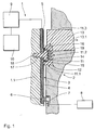
- Figure 1 shows a schematic partial section through an ink cartridge 1, which in the provided holder 2 of a franking machine sits.
- the ink cartridge 1 has in a conductor foil 3 made of electrically insulating plastic embedded, electrically conductive first and second line sections 4 and 5.
- the first line sections 4 are at one end with contact elements 6 provided, the state shown, contact springy contacts 7, which are in turn connected to a printer controller 8 of the franking machine.
- the second line sections 5 are at one end with a consumer device the ink cartridge 1 in the form of a - schematically indicated print head 9 connected. This printhead is about a - also only schematically indicated - ink reservoir 10 supplied with ink.
- a projection in the form of a nose 11 is arranged, the End face 11.1 to 11.3 with a shoulder 12 and a latch 13 of the holder 2 cooperates to fix the ink cartridge 1 in the holder 2. It understands with other variants that other or other facilities for Fixation of the ink cartridge can be provided that is not with the nose interact.
- the Connection between the printer controller 8 and the printhead 9 made.
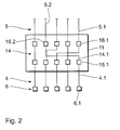
- the first, second and third line sections 4, 5 and 14 together form the electrical connection elements of the ink cartridge 1. If the nose 11, for example by breaking it down or sawing it down from the housing 1.1 to remove the ink cartridge 1, the third line sections 14 damaged or the contact between the first line sections 4 and second line sections 5 interrupted. In other words, this will the connection elements in question are destroyed, and the ink cartridge 1 can thus can no longer be operated.
- connection elements In the example shown, run into the third line sections 14 and thus Part of the connection elements within the nose 1.1.
- the connection elements also run on the outside of the nose can.
- the conductor film it is possible for the conductor film to be in one piece trained connection elements runs outside on the nose.
- the nose 11 is in the form of an anchoring pin 17 in via an anchoring means a recess in the form of a bore 18 in the housing 1.1 of the ink cartridge 1 anchored.
- This anchorage carries most of the mechanical stress, which are introduced into the ink cartridge via the fixation 12, 13. This is ensured that contact between the first and third Service sections 4 and 14 or between the second and third Line sections 5 and 14 is not affected during normal operation.
- the first contact area 15.1 of the first line section 4.1 is not - as is the case with the would correspond to a straightforward assignment - with the second contact area 16.1 of the second line section 5.1 connected but offset to it arranged second contact area 16.2 of the second line section 5.2.
- the ink cartridge can be designed in this way in other variants can, in particular the nose can be arranged so that a tapping of the Control signals on the second line sections is not possible. This can for example, simply by having the nose in one area is arranged in which the second line sections are no longer freely accessible the surface of the ink cartridge.
- connection elements Commonly used ink cartridges have a significantly higher number of connection elements. Depending on the number the connecting elements involved in the exchange result different number of possible variations of the exchange. At n Connection elements result in n! Possibilities of exchange, so yes with a relatively small number of connection elements, a sufficiently large one Number of exchanges results for each ink cartridge of one type to be provided with an individual exchange pattern.
- FIG. 1 there is also a storage device in the nose 11 embedded in the form of a chip 19, which corresponds to the first and third Line sections formed - not shown - connections with the Printer controller 8 is connected and thus read from it and additionally or can be described alternatively.
- this chip 15 are next to one Ink cartridge 1 serial number and other encrypted information for the identification and authentication of the ink cartridge, which during or after the Inserting the ink cartridge into the franking machine are queried, including the type and an expiration date of the ink is stored in the ink reservoir 10.
- an area of the chip 19 by the printer controller 8 with information be described with regard to the fill level of the ink reservoir 10. All these Information is added in the broadest sense in the area of the franking machine used to ensure the proper operation of the franking machine.
- the chip 19 also contains information relating to that described above Assignment of the first and second line sections 4 and 5, thus one Information regarding the assignment of the areas of the connection elements before and after the nose 11. This can then be read out by the printer controller 8 and then be taken into account for control. This enables the Ink cartridge 1 with the above individual assignment swaps to further reduce the likelihood of fraud.
- FIGS 3 and 4 show schematic partial sections through another preferred Execution of the consumption module according to the invention in the form of an ink cartridge 1 'for a franking machine.
- connection elements 20 are formed in one piece also embedded in a conductor foil 3 'which is on the surface 1.2' of the Housing 1.1 'of the ink cartridge 1' is attached. Over a portion of the Conductive foil 3 'sits a nose 11', which ensures that the ink cartridge 1 'only in a specially designed bracket for an associated franking machine can be used.
- the nose 11 ' is glued to the conductor foil 3'.
- the gluing is like this formed that their strength over the strength of the conductor foil 3 ', at least but lies above the strength of the connection elements 20.
- the conductor foil 3 'remains thus stick to the nose 11 'when the nose 11' is removed from the ink cartridge 1 ' and the conductor foil 3 'or the connecting elements 20 are then reached when they are reached a tension that is above the relevant strength limit or destroyed.
- the conductor foil 3 ' is in the The area of the nose 11 'is not attached to the housing 1.1', so that it is removed the nose 11 'lifts from the housing 1.1' without resistance from the housing 1.1 '. This creates just in the areas of the conductor foil 3 'between the Areas that are connected to the nose or the housing, especially high voltages, so that the described damage or Destruction comes.
- the conductor foil and the connection elements can also be used in other variants the area covered by the nose in terms of its mechanical strength be appropriately weakened to ensure that they are already at a relatively easy lifting or removing the nose from the housing destroyed become. It goes without saying that instead of the described bonding also another type of a correspondingly firm connection, for example one Welding can be selected.
- the nose 11 ' projects laterally beyond the conductor foil 3' and is there via anchors 17 'in corresponding recesses in the housing 1.1 'anchored. As in the execution, these anchorings are worn out Figure 1, the main proportion of mechanical stresses in normal operation act on the nose 11 '. This ensures that the conductor foil 3 'or Connection elements 20 not in normal operation or in normal handling be affected.
- FIG. 5 shows a schematic partial section through another preferred Embodiment, which in its basic structure from that Figures 3 and 4 are the same, so only the differences are dealt with here shall be.
- the conductor film 3 "remains when the nose 11" is removed from the housing 1.1 " the ink cartridge 1 "connected to the nose 11" and the conductor foil 3 'or Connection elements 20 "are then reached when a voltage is above their strength limit lies, damaged or destroyed.
- connection elements are not necessarily in the conductor foils described must be embedded. They are just as good be embedded or arranged directly in the housing of the consumption module.
Landscapes
- Ink Jet (AREA)
Abstract
Description
- Figur 1
- einen schematischen Teilschnitt durch ein bevorzugtes Ausführungsbeispiel des erfindungsgemäßen Verbrauchsmoduls;
- Figur 2
- eine schematische Darstellung des Verlaufs der Anschlusselemente im Bereich des Vorsprungs der Variante aus Figur 1;
- Figur 3
- einen schematischen Teilschnitt durch ein weiteres bevorzugtes Ausführungsbeispiel des erfindungsgemäßen Verbrauchs -moduls;
- Figur 4
- einen schematischen Teilschnitt durch die Ausführung aus Figur 3 entlang Linie IV-IV;
- Figur 5
- einen schematischen Teilschnitt durch ein anderes Ausführungsbeispiel des erfindungsgemäßen Verbrauchsmoduls.
Claims (10)
- Elektrisch betriebenes Verbrauchsmodul zum einsetzen in eine Halterung (2) eines elektronischen Gerätes, insbesondere Tintenpatrone für die Druckeinrichtung einer Frankiermaschine, mit einer Verbrauchseinrichtung (9), damit verbundenen elektrischen Anschlusselementen (4, 5, 14; 20; 20"), die Kontaktelemente (6) zum Verbinden des Verbrauchsmoduls (1; 1'; 1") mit einer Verbrauchsmodulsteuerung (8) des Gerätes aufweisen, und einem zum Zusammenwirken mit der Halterung vorgesehenen Vorsprung (11; 11'; 11") zum Verhindern des Einsetzens in andersartige Halterungen, dadurch gekennzeichnet, dass die Anschlusselemente (4, 5, 14; 20, 20") derart ausgebildet und/oder dem Vorsprung (11; 11'; 11") zugeordnet sind, dass sie beim unautorisierten Entfernen des Vorsprungs (11; 11'; 11") zumindest teilweise zerstört werden.
- Verbrauchsmodul nach Anspruch 1, dadurch gekennzeichnet, dass die Anschlusselemente (4, 5, 14; 20, 20") zumindest teilweise abschnittsweise an oder in dem Vorsprung (11; 11'; 11") verlaufen.
- Verbrauchsmodul nach Anspruch 2, dadurch gekennzeichnet, dass die Anschlusselemente (4, 5, 14) zumindest teilweise im Bereich des Vorsprungs (11) derart angeordnet sind, dass zwischen zum Vorsprung (11) hinführenden und vom Vorsprung (11) wegführenden Abschnitten (4, 5) der Anschlusselemente (4, 5, 14) eine gegenüber der geradlinigen Zuordnung vertauschte Zuordnung besteht.
- Verbrauchsmodul nach einem der vorhergehenden Ansprüche, dadurch gekennzeichnet, dass die Anschlusselemente (20, 20") in wenigstens einer Leiterfolie (3', 3") eingebettet sind und der Vorsprung (11'; 11") der Leiterfolie (3'; 3") derart zugeordnet ist, dass die Leiterfolie (3'; 3") beim unautorisierten Entfernen des Vorsprungs (11'; 11") unter zumindest teilweiser Zerstörung der Anschlusselemente (20; 20") beschädigt wird.
- Verbrauchsmodul nach Anspruch 4, dadurch gekennzeichnet, dass der Vorsprung (11', 11") zumindest abschnittsweise fest mit der Leiterfolie (3'; 3") verbunden ist.
- Verbrauchsmodul nach Anspruch 4 oder 5, dadurch gekennzeichnet, das der Vorsprung (11') zumindest abschnittsweise mit der Leiterfolie (3') verklebt oder verschweißt ist.
- Verbrauchsmodul nach einem der vorhergehenden Ansprüche, dadurch gekennzeichnet, dass in dem Vorsprung (11) eine Speichereinrichtung (19) zum Speichern verbrauchsmodulbezogener Informationen vorgesehen ist.
- Verbrauchsmodul nach einem der vorhergehenden Ansprüche, dadurch gekennzeichnet, dass es als Tintenpatrone (1; 1', 1") für eine Frankiermaschine ausgebildet ist.
- Verbrauchsmodul nach einem der vorhergehenden Ansprüche, dadurch gekennzeichnet, dass der Vorsprung (11) zum Zusammenwirken mit einer Verriegelungseinrichtung (12, 13) der Halterung (2) vorgesehene Verriegelungsmittel (11.1; 11.2; 11.3) aufweist.
- Elektronisches Gerät, insbesondere Frankiermaschine, mit einem Verbrauchsmodul (1; 1'; 1") nach einem der vorhergehenden Ansprüche.
Applications Claiming Priority (2)
| Application Number | Priority Date | Filing Date | Title |
|---|---|---|---|
| DE10114540 | 2001-03-21 | ||
| DE10114540A DE10114540A1 (de) | 2001-03-21 | 2001-03-21 | Verbrauchsmodul für ein elektronisches Gerät |
Publications (3)
| Publication Number | Publication Date |
|---|---|
| EP1243423A2 true EP1243423A2 (de) | 2002-09-25 |
| EP1243423A3 EP1243423A3 (de) | 2003-07-23 |
| EP1243423B1 EP1243423B1 (de) | 2005-09-07 |
Family
ID=7678893
Family Applications (1)
| Application Number | Title | Priority Date | Filing Date |
|---|---|---|---|
| EP02090085A Expired - Lifetime EP1243423B1 (de) | 2001-03-21 | 2002-03-01 | Verbrauchsmodul für ein elektronisches Gerät |
Country Status (3)
| Country | Link |
|---|---|
| US (1) | US6634740B2 (de) |
| EP (1) | EP1243423B1 (de) |
| DE (2) | DE10114540A1 (de) |
Families Citing this family (2)
| Publication number | Priority date | Publication date | Assignee | Title |
|---|---|---|---|---|
| US7182445B2 (en) * | 2003-04-25 | 2007-02-27 | Hewlett-Packard Development Company, L.P. | Replaceable printer component |
| US20110312781A1 (en) * | 2010-06-17 | 2011-12-22 | Geneasys Pty Ltd | Loc with digital memory to store genetic data updates |
Family Cites Families (11)
| Publication number | Priority date | Publication date | Assignee | Title |
|---|---|---|---|---|
| US4813912A (en) * | 1986-09-02 | 1989-03-21 | Pitney Bowes Inc. | Secured printer for a value printing system |
| DE69033928T2 (de) * | 1989-08-05 | 2002-07-18 | Canon K.K., Tokio/Tokyo | Tintenstrahlaufzeichnungsgerät und Tintenkassette dafür |
| JP3222454B2 (ja) * | 1990-02-02 | 2001-10-29 | キヤノン株式会社 | インクタンクカートリッジ |
| US5969739A (en) | 1992-03-18 | 1999-10-19 | Hewlett-Packard Company | Ink-jet pen with rectangular ink pipe |
| JP2962044B2 (ja) * | 1992-05-29 | 1999-10-12 | 富士ゼロックス株式会社 | インクタンク、インクジェットカートリッジ、及びインクジェット記録装置 |
| US5598194A (en) * | 1993-04-30 | 1997-01-28 | Hewlett-Packard Company | Wiping structure for cleaning electrical contacts for a printer and ink cartridge |
| DE19540472B4 (de) * | 1994-10-31 | 2006-05-11 | Hewlett-Packard Development Co., L.P., Houston | Tintenstrahlstift mit rechteckiger Tintenleitung |
| JPH0939265A (ja) | 1995-07-29 | 1997-02-10 | Seiko Epson Corp | プリンタにおけるインクカートリッヂ並びにその識別装置 |
| DE19613945C2 (de) * | 1996-04-06 | 1999-04-22 | Francotyp Postalia Gmbh | Wiederverwendbarkeitssperre für einen Behälter für die Tintenversorgung |
| DE19613943C2 (de) * | 1996-04-06 | 1999-04-22 | Francotyp Postalia Gmbh | Wiederverwendbarkeitssperre für einen Behälter für die Tintenversorgung |
| GB9709049D0 (en) * | 1997-05-02 | 1997-06-25 | Neopost Ltd | Postage meter with removable print head |
-
2001
- 2001-03-21 DE DE10114540A patent/DE10114540A1/de not_active Withdrawn
-
2002
- 2002-03-01 EP EP02090085A patent/EP1243423B1/de not_active Expired - Lifetime
- 2002-03-01 DE DE50204139T patent/DE50204139D1/de not_active Expired - Fee Related
- 2002-03-21 US US10/103,330 patent/US6634740B2/en not_active Expired - Fee Related
Also Published As
| Publication number | Publication date |
|---|---|
| US6634740B2 (en) | 2003-10-21 |
| DE50204139D1 (de) | 2005-10-13 |
| DE10114540A1 (de) | 2002-10-02 |
| EP1243423A3 (de) | 2003-07-23 |
| US20020135647A1 (en) | 2002-09-26 |
| EP1243423B1 (de) | 2005-09-07 |
Similar Documents
| Publication | Publication Date | Title |
|---|---|---|
| DE19630612C2 (de) | Tintenkartusche für Drucker und Tintenkartuschenidentifizierungssystem | |
| DE602006007793C5 (de) | Tintenbehälter und Platine darauf montiert | |
| DE3507871A1 (de) | Programmierbarer und mit datenverarbeitungsmitteln interaktiv kommunizierfaehiger elektronisch-mechanischer wendeflachschluessel | |
| EP0946926B1 (de) | Kontaktlose chipkarte mit transponderspule | |
| DE60018193T2 (de) | Befestigungsvorrichtung für elektrische bauelemente | |
| EP1243423B1 (de) | Verbrauchsmodul für ein elektronisches Gerät | |
| DE102005048033B4 (de) | Sicherheitsdokument | |
| DE69933837T2 (de) | Unterlage für elektrische schaltanordnung mit mitteln die entkoppeln vermeiden | |
| EP0919385B1 (de) | Umkodierung von Tintendruckköpfen | |
| DE10345257B4 (de) | Chipkarte mit Kontaktfelder und Verfahren zum Herstellen solcher Kontaktfelder | |
| DE3245681A1 (de) | Schluessel sowie dadurch zu betaetigender schliesszylinder | |
| EP0617382A2 (de) | Wertkarte mit auswechselbar gehaltertem Einsteckteil | |
| EP1492047A2 (de) | Datenträger | |
| EP3168048B1 (de) | Druckmaterialbehälter mit kurzschlussdetektion | |
| WO2011144246A1 (de) | Druckmaterialbehälter und kontaktvorrichtung | |
| EP1213817B1 (de) | Verfahren zur Ermittlung eines Erfordernisses zum Austausch eines Bauteils | |
| EP0599079B1 (de) | Sicherheitsausweiskarte | |
| DE3611441A1 (de) | Verfahren zum auslesen und/oder einlesen von daten aus bzw. in eine chipkarte sowie chipkarte und lese- und/oder schreibgeraet zur verwendung bei diesem verfahren | |
| DE69525784T2 (de) | Programmeinstellvorrichtung für eine Zeitregistriereinrichtung | |
| DE202019102437U1 (de) | Platine für eine Druckerpatrone, Druckerpatrone und Drucksystem | |
| DE102006038486B4 (de) | Sicherungselement zum Schutz von Datenträgerkarten | |
| DE10248390B4 (de) | Display für tragbaren elektronischen Datenträger | |
| DE102024111706A1 (de) | Kartenförmiger Datenträger, Verfahren zum Herstellen eines kartenförmigen Datenträgers sowie Identifikationsverfahren | |
| EP1574358A1 (de) | Ausweisdokument mit einem integrierten Schaltkreis | |
| DE10208172B4 (de) | Zwischenträger zum Einsetzen in einen Träger und Träger mit einem Zwischenträger |
Legal Events
| Date | Code | Title | Description |
|---|---|---|---|
| PUAI | Public reference made under article 153(3) epc to a published international application that has entered the european phase |
Free format text: ORIGINAL CODE: 0009012 |
|
| AK | Designated contracting states |
Kind code of ref document: A2 Designated state(s): AT BE CH CY DE DK ES FI FR GB GR IE IT LI LU MC NL PT SE TR |
|
| AX | Request for extension of the european patent |
Free format text: AL;LT;LV;MK;RO;SI |
|
| PUAL | Search report despatched |
Free format text: ORIGINAL CODE: 0009013 |
|
| AK | Designated contracting states |
Designated state(s): AT BE CH CY DE DK ES FI FR GB GR IE IT LI LU MC NL PT SE TR |
|
| AX | Request for extension of the european patent |
Extension state: AL LT LV MK RO SI |
|
| RIC1 | Information provided on ipc code assigned before grant |
Ipc: 7B 41J 2/175 A Ipc: 7G 07B 17/00 B |
|
| 17P | Request for examination filed |
Effective date: 20030813 |
|
| AKX | Designation fees paid |
Designated state(s): CH DE FR GB IT LI |
|
| 17Q | First examination report despatched |
Effective date: 20040329 |
|
| GRAP | Despatch of communication of intention to grant a patent |
Free format text: ORIGINAL CODE: EPIDOSNIGR1 |
|
| GRAS | Grant fee paid |
Free format text: ORIGINAL CODE: EPIDOSNIGR3 |
|
| GRAA | (expected) grant |
Free format text: ORIGINAL CODE: 0009210 |
|
| AK | Designated contracting states |
Kind code of ref document: B1 Designated state(s): CH DE FR GB IT LI |
|
| REG | Reference to a national code |
Ref country code: GB Ref legal event code: FG4D Free format text: NOT ENGLISH |
|
| REG | Reference to a national code |
Ref country code: CH Ref legal event code: EP |
|
| REF | Corresponds to: |
Ref document number: 50204139 Country of ref document: DE Date of ref document: 20051013 Kind code of ref document: P |
|
| RAP2 | Party data changed (patent owner data changed or rights of a patent transferred) |
Owner name: FRANCOTYP-POSTALIA GMBH |
|
| GBT | Gb: translation of ep patent filed (gb section 77(6)(a)/1977) |
Effective date: 20060104 |
|
| ET | Fr: translation filed | ||
| PLBE | No opposition filed within time limit |
Free format text: ORIGINAL CODE: 0009261 |
|
| STAA | Information on the status of an ep patent application or granted ep patent |
Free format text: STATUS: NO OPPOSITION FILED WITHIN TIME LIMIT |
|
| 26N | No opposition filed |
Effective date: 20060608 |
|
| PGFP | Annual fee paid to national office [announced via postgrant information from national office to epo] |
Ref country code: DE Payment date: 20070213 Year of fee payment: 6 |
|
| PGFP | Annual fee paid to national office [announced via postgrant information from national office to epo] |
Ref country code: CH Payment date: 20070314 Year of fee payment: 6 |
|
| PGFP | Annual fee paid to national office [announced via postgrant information from national office to epo] |
Ref country code: GB Payment date: 20070322 Year of fee payment: 6 |
|
| PGFP | Annual fee paid to national office [announced via postgrant information from national office to epo] |
Ref country code: IT Payment date: 20070623 Year of fee payment: 6 |
|
| PGFP | Annual fee paid to national office [announced via postgrant information from national office to epo] |
Ref country code: FR Payment date: 20070319 Year of fee payment: 6 |
|
| REG | Reference to a national code |
Ref country code: CH Ref legal event code: PL |
|
| GBPC | Gb: european patent ceased through non-payment of renewal fee |
Effective date: 20080301 |
|
| REG | Reference to a national code |
Ref country code: FR Ref legal event code: ST Effective date: 20081125 |
|
| PG25 | Lapsed in a contracting state [announced via postgrant information from national office to epo] |
Ref country code: LI Free format text: LAPSE BECAUSE OF NON-PAYMENT OF DUE FEES Effective date: 20080331 Ref country code: CH Free format text: LAPSE BECAUSE OF NON-PAYMENT OF DUE FEES Effective date: 20080331 Ref country code: DE Free format text: LAPSE BECAUSE OF NON-PAYMENT OF DUE FEES Effective date: 20081001 |
|
| PG25 | Lapsed in a contracting state [announced via postgrant information from national office to epo] |
Ref country code: FR Free format text: LAPSE BECAUSE OF NON-PAYMENT OF DUE FEES Effective date: 20080331 |
|
| PG25 | Lapsed in a contracting state [announced via postgrant information from national office to epo] |
Ref country code: GB Free format text: LAPSE BECAUSE OF NON-PAYMENT OF DUE FEES Effective date: 20080301 |
|
| PG25 | Lapsed in a contracting state [announced via postgrant information from national office to epo] |
Ref country code: IT Free format text: LAPSE BECAUSE OF NON-PAYMENT OF DUE FEES Effective date: 20080301 |