EP1243335A1 - Katalysator und verfahren zu dessen herstellung - Google Patents
Katalysator und verfahren zu dessen herstellung Download PDFInfo
- Publication number
- EP1243335A1 EP1243335A1 EP00976292A EP00976292A EP1243335A1 EP 1243335 A1 EP1243335 A1 EP 1243335A1 EP 00976292 A EP00976292 A EP 00976292A EP 00976292 A EP00976292 A EP 00976292A EP 1243335 A1 EP1243335 A1 EP 1243335A1
- Authority
- EP
- European Patent Office
- Prior art keywords
- support
- thin film
- alumina
- silicon
- ceramic
- Prior art date
- Legal status (The legal status is an assumption and is not a legal conclusion. Google has not performed a legal analysis and makes no representation as to the accuracy of the status listed.)
- Granted
Links
Images


Classifications
-
- B—PERFORMING OPERATIONS; TRANSPORTING
- B01—PHYSICAL OR CHEMICAL PROCESSES OR APPARATUS IN GENERAL
- B01D—SEPARATION
- B01D53/00—Separation of gases or vapours; Recovering vapours of volatile solvents from gases; Chemical or biological purification of waste gases, e.g. engine exhaust gases, smoke, fumes, flue gases, aerosols
- B01D53/34—Chemical or biological purification of waste gases
- B01D53/92—Chemical or biological purification of waste gases of engine exhaust gases
- B01D53/94—Chemical or biological purification of waste gases of engine exhaust gases by catalytic processes
- B01D53/9445—Simultaneously removing carbon monoxide, hydrocarbons or nitrogen oxides making use of three-way catalysts [TWC] or four-way-catalysts [FWC]
- B01D53/945—Simultaneously removing carbon monoxide, hydrocarbons or nitrogen oxides making use of three-way catalysts [TWC] or four-way-catalysts [FWC] characterised by a specific catalyst
-
- B—PERFORMING OPERATIONS; TRANSPORTING
- B01—PHYSICAL OR CHEMICAL PROCESSES OR APPARATUS IN GENERAL
- B01J—CHEMICAL OR PHYSICAL PROCESSES, e.g. CATALYSIS OR COLLOID CHEMISTRY; THEIR RELEVANT APPARATUS
- B01J21/00—Catalysts comprising the elements, oxides, or hydroxides of magnesium, boron, aluminium, carbon, silicon, titanium, zirconium, or hafnium
- B01J21/02—Boron or aluminium; Oxides or hydroxides thereof
- B01J21/04—Alumina
-
- B—PERFORMING OPERATIONS; TRANSPORTING
- B01—PHYSICAL OR CHEMICAL PROCESSES OR APPARATUS IN GENERAL
- B01J—CHEMICAL OR PHYSICAL PROCESSES, e.g. CATALYSIS OR COLLOID CHEMISTRY; THEIR RELEVANT APPARATUS
- B01J23/00—Catalysts comprising metals or metal oxides or hydroxides, not provided for in group B01J21/00
- B01J23/38—Catalysts comprising metals or metal oxides or hydroxides, not provided for in group B01J21/00 of noble metals
- B01J23/54—Catalysts comprising metals or metal oxides or hydroxides, not provided for in group B01J21/00 of noble metals combined with metals, oxides or hydroxides provided for in groups B01J23/02 - B01J23/36
- B01J23/56—Platinum group metals
- B01J23/63—Platinum group metals with rare earths or actinides
-
- B—PERFORMING OPERATIONS; TRANSPORTING
- B01—PHYSICAL OR CHEMICAL PROCESSES OR APPARATUS IN GENERAL
- B01J—CHEMICAL OR PHYSICAL PROCESSES, e.g. CATALYSIS OR COLLOID CHEMISTRY; THEIR RELEVANT APPARATUS
- B01J37/00—Processes, in general, for preparing catalysts; Processes, in general, for activation of catalysts
- B01J37/02—Impregnation, coating or precipitation
- B01J37/0201—Impregnation
-
- B—PERFORMING OPERATIONS; TRANSPORTING
- B01—PHYSICAL OR CHEMICAL PROCESSES OR APPARATUS IN GENERAL
- B01J—CHEMICAL OR PHYSICAL PROCESSES, e.g. CATALYSIS OR COLLOID CHEMISTRY; THEIR RELEVANT APPARATUS
- B01J37/00—Processes, in general, for preparing catalysts; Processes, in general, for activation of catalysts
- B01J37/02—Impregnation, coating or precipitation
- B01J37/0215—Coating
-
- B—PERFORMING OPERATIONS; TRANSPORTING
- B01—PHYSICAL OR CHEMICAL PROCESSES OR APPARATUS IN GENERAL
- B01J—CHEMICAL OR PHYSICAL PROCESSES, e.g. CATALYSIS OR COLLOID CHEMISTRY; THEIR RELEVANT APPARATUS
- B01J37/00—Processes, in general, for preparing catalysts; Processes, in general, for activation of catalysts
- B01J37/02—Impregnation, coating or precipitation
- B01J37/0234—Impregnation and coating simultaneously
-
- B—PERFORMING OPERATIONS; TRANSPORTING
- B01—PHYSICAL OR CHEMICAL PROCESSES OR APPARATUS IN GENERAL
- B01J—CHEMICAL OR PHYSICAL PROCESSES, e.g. CATALYSIS OR COLLOID CHEMISTRY; THEIR RELEVANT APPARATUS
- B01J37/00—Processes, in general, for preparing catalysts; Processes, in general, for activation of catalysts
- B01J37/02—Impregnation, coating or precipitation
- B01J37/0236—Drying, e.g. preparing a suspension, adding a soluble salt and drying
-
- B—PERFORMING OPERATIONS; TRANSPORTING
- B01—PHYSICAL OR CHEMICAL PROCESSES OR APPARATUS IN GENERAL
- B01J—CHEMICAL OR PHYSICAL PROCESSES, e.g. CATALYSIS OR COLLOID CHEMISTRY; THEIR RELEVANT APPARATUS
- B01J27/00—Catalysts comprising the elements or compounds of halogens, sulfur, selenium, tellurium, phosphorus or nitrogen; Catalysts comprising carbon compounds
- B01J27/20—Carbon compounds
- B01J27/22—Carbides
- B01J27/224—Silicon carbide
-
- Y—GENERAL TAGGING OF NEW TECHNOLOGICAL DEVELOPMENTS; GENERAL TAGGING OF CROSS-SECTIONAL TECHNOLOGIES SPANNING OVER SEVERAL SECTIONS OF THE IPC; TECHNICAL SUBJECTS COVERED BY FORMER USPC CROSS-REFERENCE ART COLLECTIONS [XRACs] AND DIGESTS
- Y02—TECHNOLOGIES OR APPLICATIONS FOR MITIGATION OR ADAPTATION AGAINST CLIMATE CHANGE
- Y02T—CLIMATE CHANGE MITIGATION TECHNOLOGIES RELATED TO TRANSPORTATION
- Y02T10/00—Road transport of goods or passengers
- Y02T10/10—Internal combustion engine [ICE] based vehicles
- Y02T10/12—Improving ICE efficiencies
Definitions
- This invention relates to a catalyst for the purification of an exhaust gas and a method of producing the same, and more particularly to a catalyst capable of removing carbon monooxide (CO) and hydrocarbon (HC) included in the exhaust gas through oxidation, removing nitrogen oxide (No x ) by reduction efficiently, and being small in the pressure loss and high in the collection ratio of diesel particulates.
- CO carbon monooxide
- HC hydrocarbon
- a honeycomb type filter 100 wherein each cell 101 forming a path of the exhaust gas is shaped into a honeycomb form with a porous silicon carbide sintered body having excellent heat resistance and thermal conductivity and these cells 101 are alternately closed. It is usual to be a catalyst system that the honeycomb filter 100 is connected to an exhaust side of the diesel engine to decompose PM (particulate mass), HC, Co and so on deposited in the filer through oxidation.
- a holding layer made of ⁇ -alumina is formed on a surface of a filtering wall (cell wall) 102 in a honeycomb-shaped heat-resistant support of, for example, cordierite or the like and further an active catalyst component made of a noble metal such as Pt, Pd, Rh or the like is held on the carrier layer.
- the alumina layer wash-coated by the conventional technique 103 (wash-coat alumina layer) is formed in a thin film uniformly coating a wall face of a filtering wall 102 as shown in FIG. 2(a), and has a pore structure as shown by a partial enlarged view in FIG. 2(b).
- a pore size in such a pore structure is mainly 20-500 ⁇ , and a specific surface area is usually 50-300 m 2 /g.
- the alumina layer 103 is a catalyst holding layer for dispersion-supporting an active catalyst component such as a noble metal or the like on its surface, so that it is required to have a large specific surface area and a certain thickness (about 50-100 ⁇ m).
- the wash-coat alumina layer 103 is small in the pore size and porosity and large in the passing resistance, so that there is a problem that the pressure loss considerably increases as compared with the support having no alumina layer.
- the wash-coat alumina layer 103 uniformly coats the surface of the support as a filtering wall 102 but also is poor in the adhesion property, so that it is feared to peel off from the support in the cleaning of ash deposited in the purification of the exhaust gas.
- the wash-coat alumina layer 103 is a pore structure, but the pore size is as small as 20-500 ⁇ , so that when it is exposed to a higher temperature for a long time, the sintering proceeds and phase transition to ⁇ -phase is caused to decrease a surface area and hence there is caused a problem that the heat resistance is poor.
- the surface of the holding layer for the active component, particularly alumina holding layer covering the support is maintained at a stable state over a long time.
- an object of the invention to propose a catalyst having large pore size and porosity and small pressure loss and a high collecting efficiency of diesel particulates though an alumina thin film is formed on a surface of a support as well as a method of producing the same.
- the invention is fundamentally a catalyst comprising a porous ceramic support, particularly silicon-containing support and an active catalyst component dispersion held on a surface thereof, wherein each surface of particles constituting the ceramic support is covered with a thin film of alumina, particularly alumina thin film containing a rare earth oxide. And also, it is advantageous to use a catalyst wherein the active catalyst component is held on irregular surfaces of the alumina thin film covering the surface of each particle.
- the ceramic support particularly silicon-containing ceramic support in a preferable embodiment is favorable to be constructed with a silicide support containing a non-oxide ceramic such as silicon carbide, silicon nitride or the like, or an oxide ceramic such as sialon, mullite, cordierite or the like.
- a silicide support containing a non-oxide ceramic such as silicon carbide, silicon nitride or the like, or an oxide ceramic such as sialon, mullite, cordierite or the like.
- the silicon containing ceramic support is used as a porous body, fiber-shaped body or pellet-shaped body, preferably is formed in a honeycomb-shaped porous silicon carbide sintered body.
- a preferable embodiment is a support having SiO 2 layer on its surface, an amount of which in the support is 0.001-20 mass%.
- the alumina thin film covering the surface of each particle in the ceramic support contains a rare earth oxide such as ceria (CeO 2 ), lanthana (La 2 O 3 ) or the like in its surface and/or inside and a micro-sectional form thereof shows a haired structure that fine fibers having a diameter: 2-50 nm, a length: 20-300 nm and a ratio of total length/diameter of 5-100 are forested with each other.
- the alumina thin film is an amount of 0.1-15 mass% as an alumina amount based on the support.
- the rare earth oxide-containing alumina thin film covering the support is covered in an amount of 0.1-15 mass% as converted by an alumina amount based on the support, and the rare earth oxide contained in the alumina thin film has a content of 10-80 mass% based on the alumina.
- At least a part of the rare earth oxide is a composite oxide with zirconium.
- a particle size of the composite oxide of the rare earth oxide with zirconium is a size of 1-30 nm.
- the catalyst support can be produced by forming an alumina thin film or a rare earth oxide-containing alumina thin film made from a rare earth oxide and alumina on a surface of each particle constituting a ceramic support, particularly silicon-containing ceramic support through the following steps (a)-(e) and then holding an active catalyst component such as a noble metal or the like on irregular surfaces of such an alumina thin film.
- the catalyst can be produced by forming an alumina thin film or a rare earth oxide-containing alumina thin film containing a rare earth oxide and alumina on a surface of each particle constituting a ceramic support, particularly silicon-containing ceramic support through the following steps (a)-(f) and then holding an active catalyst component such as a noble metal or the like on irregular surfaces of such an alumina thin film.
- the composition, structure and properties of the ceramic support, particularly silicon-containing support are as mentioned above.
- the alumina thin film covering each ceramic particle surface is the same as mentioned above.
- the rare earth oxide is a composite oxide with zirconium, and a particle size thereof is a size of 1-30 nm as mentioned above.
- the active catalyst component is used at least one metal selected from the group consisting of Pt, Rh, Pd, Ce, Cu, V, V, Fe, Tu and Ag, or an alloy or a compound thereof.
- FIG. 1 is a schematic view of a typical catalyst support
- FIG. 2 is a conceptual view of the conventional wash-coat alumina layer
- FIGS. 3(a), (b) and (c) are conceptual views of an alumina thin film according to the invention, respectively
- FIG. 4 is an electron microphotograph showing a particle structure of a catalyst support
- FIG. 5 is a schematic view of a pressure loss
- FIG. 6 is a diagrammatical view explaining a mechanism of improving an oxidation rate by addition of CeO 2
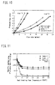
- FIG. 7 is a comparative graph showing oxidation characteristic of soot upon regenerating property of DPF
- FIG. 8 is a comparative graph showing a regenerating rate upon a regenerating property of DPF
- FIG. 1 is a schematic view of a typical catalyst support
- FIG. 2 is a conceptual view of the conventional wash-coat alumina layer
- FIGS. 3(a), (b) and (c) are conceptual views of an alumina thin film according to the invention,
- FIG. 9 is a comparative graph on a regenerating ratio of DPF;
- FIG. 10 is a comparative graph showing a pressure loss characteristic in Example 1;
- FIG. 11 is a comparative graph showing a specific surface area in Example 1;
- FIG. 12 is a comparative graph showing a comparative graph showing a heat resistance in Example 1;
- FIG. 13 is a comparative graph showing a pressure loss characteristic in Example 2;
- FIG. 14 is a comparative graph of THC, CO purification property in Example 2;
- FIG. 15 is a comparative graph showing a burning characteristic of soot in Example 2;
- FIG. 16 is a comparative graph of a pressure loss characteristic in Example 3;
- FIG. 17 is a comparative graph of a specific surface area in Example 3;
- FIG. 18 is a comparative graph of heat resistance of (a) alumina thin film and (b) catalyst in Example 3.
- a filtering wall 2 of a support 1 is formed with a porous silicon-containing ceramic sintered body made of a ceramic, particularly a silicon-containing ceramic, for example, silicon carbide as a preferable embodiment (hereinafter referred to as "porous SiC sintered body” simply) and a surface of the filtering wall 2, particularly each surface of SiC particles is covered with an alumina thin film as a catalyst holding layer at a given thickness and an active catalyst component such as Pt, Pd or the like (hereinafter referred to as “active component” simply) is held on the alumina thin film.
- a porous silicon-containing ceramic sintered body made of a ceramic, particularly a silicon-containing ceramic, for example, silicon carbide as a preferable embodiment
- active component such as Pt, Pd or the like
- the ceramic support used in the catalyst according to the invention there can be used ones obtained by adding and mixing silicon carbide powder, silicon nitride powder, oxide ceramic or a silicon-containing ceramic powder of an oxide such as sialon, mullite, cordierite or the like with an organic binder, a lubricant, a plasticizer and water, extrusion-shaping them and sintering. In this way, a wall-flow honeycomb type filter is formed as shown in FIG. 1.
- SiC sintered body As an example of silicon-containing ceramic support, there will be described an example using SiC sintered body below.
- the support (filter) 1 is constructed with SiC sintered body of substantially a square in section wherein plural through-holes (cells) are regularly formed along an axial line direction thereof. These cells are separated from each other through a filtering wall 2 (which may be called as “cell wall 2" hereinafter), and arranged so as to show a checkered pattern wherein opening portion of each cell is sealed at its one end face side with a sealing body 104 and opened at the other end face side and each end face as a whole is an opened part or a sealed part. And also, many cells 101 having a square shape at section are formed in the support (filter) 1 of the SiC sintered body. In other words, such a filter has a honeycomb structure.
- a density of the cell 101 is about 200 cells/square inch. That is, about a half of these cells 101 are opened at upstream side end faces, and the reminder is opened at downstream side end faces, and a thickness of the cell wall 2 separating the cells 101 from each other is set to be about 0.4 mm.
- the support 1 of the SiC sintered body has a structure of partitioning with porous cell walls 2 as shown in FIG. 3(a). It is favorable that pores in the porous cell wall 2 has an average value of pore size of 5 ⁇ m-15 ⁇ m as measured by a mercury pressure process and a value of standard deviation in pore size distribution when the pore size is represented by customary logarithm is not more than 0.20.
- the cell wall 2 has a pore size of the above range, it is also suitable for collecting fine particulates. That is, when the average pore size of the cell wall 2 is set to the above range, diesel particulates can surely be collected. On the other hand, when the average value of the pore size of the cell wall 2 is less than 5 ⁇ m, the pressure loss when the exhaust gas passes through the inner wall becomes extremely large and there is a risk of stopping the engine, while when the average value of the pore size exceeds 15 ⁇ m, fine particulates can not efficiently be collected.
- a starting material is formed by compounding 70 parts by weight of silicon carbide powder having an average particle size of about 10 ⁇ m, about 30 parts by weight of silicon carbide powder having an average particle size of about 0.5 ⁇ m, about 6 parts by weight of methyl cellulose as a binder based on 100 parts by weight of the ceramic powder, about 25 parts by weight of a dispersion consisting of an organic solvent and water based on 100 parts by weight of the ceramic powder.
- the starting material is milled and extruded into a honeycomb shape and thereafter a part of cells 101 is sealed to form a checkered pattern.
- the resulting shaped body is dried and degreased and fired in an inert atmosphere at 2200°C for 4 hours to obtain a desired ceramic support.
- the silicon content is favorable to be 0.01-10 mass%. Because, when the silicon content is less than 0.01 mass%, Si feeding ability is lacking and the effect of improving the heat resistance is less, while when the silicon content exceeds 10 mass%, the strength of the honeycomb filter lowers. Even in the other silicon-containing ceramics, the silicon content is favorably 0.01-10 mass% likewise the above case, more preferably 0.01-5 mass%, further preferably 0.01-2 mass%.
- a most important feature in the invention lies in that the surface of the cell wall 2 in the support 1, particularly each surface of ceramic particles constituting the cell wall 2 is separately covered with an alumina thin film. More concretely, each particle surface of the SiC sintered body constituting the cell wall 2 is separately covered with the alumina thin film by various methods. That is, the cell wall 2 is constructed as an aggregate of the ceramic particles each covered with the alumina thin film.
- FIG. 2(b) shows the conventional technique that an alumina layer 103 is uniformly coated and formed on the surface of the cell wall 102 by a wash-coat method.
- FIGS. 3(b) and (c) are diagrammatic views of a support used in the invention, wherein each surface of SiC particles 4 constituting the cell wall 2 is separately covered with the alumina thin film 3 (means both a case containing rare earth oxide and a case containing no rare earth oxide, hereinafter abbreviated as "alumina thin film” simply).
- the holding film (alumina thin film) as a characteristic feature in the catalyst according to the invention is not formed by a method wherein the alumina layer 103 is merely uniformly coated onto the wall face of the cell wall 2 as a filtering wall for exhaust gas as disclosed in the conventional technique.
- the alumina layer 103 is merely uniformly coated onto the wall face of the cell wall 2 as a filtering wall for exhaust gas as disclosed in the conventional technique.
- gaps between the particles are sealed to obstruct the permeation.
- each surface of the SiC particles constituting the cell wall 2 is separately covered with the alumina thin film 3. In the invention, therefore, the pores are maintained as they are without clogging the pores of the cell wall 2 itself, i.e.
- the gap produced between the particles so that the pressure loss is considerably small as compared with the conventional alumina thin film 103.
- the heat resistance is excellent, and further the alumina thin film 3 separately covers each SiC particle itself, so that when, for example, the washing is conducted, the thin film is not peeled off from the cell wall and becomes excellent in the washing resistance.
- FIG. 4 shows a comparison between an electron microphotograph (x10K), (x30K) of the ceramic support formed by covering each surface of SiC particles with the alumina thin film (invention) and an electron microphotograph (x10K), (x30K) of the ceramic support formed by uniformly covering the surface of the cell wall with the alumina film (conventional technique).
- alumina are forested on the each surface of SiC particles in needle form (fibrous form), which is clearly seen to be an apparently haired structure as shown in FIG. 3(c).
- the structure of the alumina thin film required in the catalyst according to the invention i.e. crystal structure of the alumina thin film formed by covering each surface of particles such as SiC or the like contains at least one of ⁇ -Al 2 O 3 , ⁇ -Al 2 O 3 and ⁇ -Al 2 O 3 , wherein a diameter of fibrous protruded alumina constituting the alumina thin film is 2-50 nm and a length thereof is 20-300 nm and a ratio of total length/diameter is 5-50. And also, a thickness of the thin film is not more than 0.5 ⁇ m, and a specific surface area of alumina as an alumina is favorable to be 50-300 m 2 /g.
- the thickness of alumina thin film used herein means an average of distances from the surface of the SiC particle to tops of alumina fibers protruded therefrom. Moreover, the diameter of alumina is more desirably 5-20 nm, and the ratio of total length/diameter is more desirably 10-30.
- the reason why the properties of the fibrous protruded alumina thin film are restricted a mentioned above is due to the fact that when the length of the fibrous protruded alumina is less than 20 nm, it is difficult to ensure the surface area, while when it exceeds 300 nm, the structure becomes brittle. And also, when the diameter is less than 2 nm, it is equal to or smaller than the size of the catalyst such as noble mental or the like and does not act as a holding layer, while when it exceeds 50 nm, it is difficult to ensure the desired specific surface area.
- the reason why the specific surface area of the alumina thin film is restricted as mentioned above is due to the fact that when the specific surface area is less than 50 m 2 /g, sintering of the fibrous protruded alumina excessively proceeds and the durability is poor, while when it exceeds 300 m 2 /g, the fibrous protruded alumina becomes finer and does not act as so-called holding layer and structurally brittle. Moreover, a preferable specific surface area is a range of 50-200 m 2 /g.
- an amount of alumina thin film as a holding layer is preferable to be 0.5-15 mass% as an alumina ratio.
- a preferable amount is 1-4 mass%.
- the pressure loss property when the exhaust gas passes through the cell wall as a filtering wall is considered as follows. That is, the pressure loss when a diesel exhaust gas passes through the support (filter) can be shown in FIG. 5.
- resistances ⁇ P1 resistance due to the narrowing of the opening in the path
- ⁇ P2 resistance passing through small tube
- ⁇ P3 resistance passing through wall
- ⁇ P4 resistance passing through deposited diesel particulates and is a value of 2-3 times or more of the initial pressure loss.
- a surface area of the support having a cell structure of 14/200 is 8.931 cm 2 /cm 3 and a density of the support is 0.675 g/cm 3 , so that a surface area of cell walls is 0.0013 m 2 /g.
- the surface area of the fine pore in the cell wall is 0.12 m 2 /g as measured by a mercury porosimeter and is about 100 times the surface area of the cell wall.
- the thickness of the alumina layer is required to be 50 ⁇ m.
- a resistance passing through the alumina layer increases in addition to the resistance ⁇ P3 passing through the inside of the cell wall.
- ⁇ P1 is large.
- the pressure loss becomes considerably large as compared with the filter not coated with the alumina. This tendency becomes more conspicuous when the particulates are deposited on the filter.
- the thickness is about 0.5 ⁇ m at maximum.
- the resistance ⁇ P3 is slightly increased, but the other pressure loss can substantially be ignored, so that the pressure loss property is considerably improved as compared with that of the conventional wash-coat layer.
- alumina has a high specific surface area and is suitable as a catalyst carrying film. particularly, it is presently desired to develop a catalyst having a high heat resistance stably operating at a higher temperature, and the alumina carrying film is required to have a higher heat resistance accompanied therewith.
- each alumina particle is rendered into a fine fiber and 2 ⁇ a rare earth oxide such as ceria or the like is included.
- contact points between the alumina particles can be decreased, and the particle growth is controlled by lowering the sintering rate and hence the specific surface area can be increased to improve the heat resistance.
- the alumina thin film covering each surface of the particles of the support shows a haired structure at its micro-section that the alumina particles are forested in form of fine fibers, so that mutual contact points of the adjoining alumina fine fibers decrease and hence the heat resistance is considerably improved.
- the heat resistance is improved by the addition of ceria or the like.
- the reason is due to the effect of forming a new compound on the surface of the crystal grains constituting the alumina to obstruct the growth of the alumina particles with each other.
- Si is supplied from SiC or SiO 2 existing on a surface layer of Sic, which acts to shield a mass transfer path to thereby improve the heat resistance. According to the inventors' studies, it has been confirmed that when SiC is intentionally treated at a high temperature to form an oxide, the heat resistance is further improved.
- the particulate deposited on the surface of the cell wall is mainly carbon, which can be removed through oxidation by a method such as combustion or the like.
- substances are retained as an ash after the combustion. They are oxides or sulfates of compounds of Ca, Mg, Zn and the like adding to an engine oil for serving as a neutralizing agent, a lubricant or the like, or deposits of a catalyst such as CeO 2 , CuO or the like included in a fuel for combusting carbon together with the particulates on the surface of the filter.
- These ashes are deposited to increase the pressure loss of the filter during the running of the vehicle over a long time, so that they are necessary to be washed with a high pressure water or the like. In this case, the ashes can completely be removed by washing at a pressure of not less than 30 kg/cm 2 .
- the carrier alumina thin film used in the invention
- the surface of each particle constituting the SiC carrier is thinly covered with the alumina, and Si is supplied from SiC constituting the carrier and chemically bonded to closely adhere particles to each other, so that the adhesion property is high and hence the resistance to washing is high and the durability as a coating is strong.
- the alumina thin film wherein a rare earth oxide such as ceria (CeO 2 ) or lanthana (La 2 O 3 ) is added in an amount of about 10-80 mass%, preferably 20-40 mass% to Al 2 O 3 to uniformly disperse these oxides in the surface and inside of the thin film.
- a rare earth oxide such as ceria (CeO 2 ) or lanthana (La 2 O 3 ) is added in an amount of about 10-80 mass%, preferably 20-40 mass% to Al 2 O 3 to uniformly disperse these oxides in the surface and inside of the thin film.
- the supply of oxygen into the exhaust gas is activated by the action of adjusting oxygen concentration inherent to the ceria to improve the efficiency of combustion-removing "soot (diesel particulates)" adhered to the filter and hence considerably improve the regeneration ratio of the catalyst support.
- the rare earth oxide such as ceria or the like serves to not only improve the heat resistance of the alumina but also adjust the oxygen concentration on the surface of the catalyst.
- hydrocarbon or carbon monooxide existing in the exhaust gas are removed by an oxidation reaction and NOx is removed by reduction reaction.
- the composition of the exhaust gas always varies between rich region and lean region of the fuel, so that an atmosphere acting to the surface of the catalyst violently varies.
- the ceria added to the catalyst is relatively small in an oxidation-reduction potential between Ce 3+ and Ce 4+ , so that a reaction of the following formula: 2CeO 2 ⁇ Ce 2 O 3 + 1/2O 2 reversibly proceeds.
- FIG. 6 explains a mechanism of oxidation rate on each catalyst when Al 2 O 3 thin film (a) not added with ceria (CeO 2 ) or Al 2 O 3 thin film (b) added with ceria is used as a holding film.
- the catalyst (a) containing no CeO 2 oxidizes soot by activating oxygen in the exhaust gas.
- oxygen in the fluid should be activated, so that the efficiency is poor.
- the catalyst (b) containing CeO 2 supplies oxygen according to the following reaction; CeO 2 ⁇ CeO 2-x + x/2O 2 That is, oxygen discharged into an atmosphere and oxygen in the exhaust gas react are activated by the catalyst (noble metal) and react with soot (carbon) to form CO 2 (CeO 2-x is oxidized into original CeO 2 ). And also, CeO 2 and the soot directly contact with each other, so that even if an amount of oxygen discharged is small, the soot can be efficiently oxidized.
- CeO 2 holds the catalyst (noble metal) to increase OSC (oxygen storing capacity). Because, the catalyst (noble metal) activates oxygen in the exhaust gas and also oxygen on the CeO 2 surface near to the noble metal is activated to increase the above OSC.
- FIGS. 7 and 8 show experimental results on regeneration properties of Pt/CeO 2 /needle Al 2 O 3 catalyst (invention example) and Pt/needle Al 2 O 3 (comparative example) and Pt/Al 2 O 3 (wash coat) catalyst with respect to the effect of adding the rare earth oxide such as ceria or the like to the alumina thin film, respectively.
- FIG. 9 shows a comparison of the regeneration ratios themselves, from which it is clear that the effect in the invention example (ceria containing catalyst) becomes conspicuous.
- the rare earth oxide it is more favorable to use a composite oxide of, for example, rare earth element and zirconium in addition to the single oxide (CeO 2 ) as mentioned above. It is considered that since zirconium oxide is included in the rare earth oxide, the grain growth of the rare earth oxide is suppressed to improve the property of controlling the oxygen concentration.
- the rare earth oxide taking a form of a composite oxide with zirconium is favorable to have a particle size of about 1-30 nm, more preferably 2-20 nm.
- the particle size is less than 1 nm, it is difficult to produce the composite oxide.
- the particle size exceeds 30 nm, the particles are apt to be sintered and the surface area of the particle becomes small and hence the contact area with the exhaust gas becomes small and there is left a problem that the activity weakens. Further, there is a problem that the pressure loss in the passing of the exhaust gas becomes large.
- impregnation method such as an evaporation drying method, an equilibrium adsorption method, an incipient wetness method or a spraying method is applicable.
- the incipient wetness method is advantageous.
- This method is a method wherein an aqueous solution containing a given amount of the active component is added dropwise onto the support and at a time of uniformly and slightly wetting the surface of the support (Incipient), the impregnation of the active component into pores of the support is stopped and then the drying and firing are carried out. That is, it is carried out by dropwisely adding the active component containing solution onto the surface of the support with a burette or an injection cylinder. The holding amount is adjusted by a concentration in the solution.
- binary, ternary alloys such as Pt/Rh system, Pt/Rh/Pd system and the like are used as a noble metal component usable as the active catalyst component. They are used as a cocatalyst as mentioned above.
- the rare earth oxide such as ceria, lanthana or the like, and such a catalyst is less in the deterioration through poison (lead poison, phosphorus poison, sulfur poison) and small in the thermal deterioration and is excellent in the durability.
- a characteristic of the method of producing the catalyst according to the invention lies in a point that an alumina thin film or an alumina thin film containing a rare earth oxide is formed on irregular surfaces formed by particles of the ceramic support, particularly silicon-containing ceramic support through a sol-gel method.
- each particle surface of the ceramic particles such as SiC or the like forming the cell wall is covered with the alumina thin film through immersion of the solution, and then preliminarily fired and subjected to a step of treating with hot water, whereby the micro-sectional structure of the alumina thin film is changed into an alumina thin film (holding film) having a haired structure of foresting fine fibers of alumina and a given amount of an active component is adsorbed and fixed (held) onto the surface of the alumina thin film.
- This step is a treatment wherein oxidation is carried out by heating at 800-1600°C for 5-100 hours for providing Si amount assisting chemical bonding with alumina onto each surface of silicon containing ceramic particles such as SiC or the like.
- SiC sintered body itself contains about 0.8 mass% of SiO 2 . This is existent onto the surface of SiC or in the grain boundary thereof, from which it is easily guessed to supply Si. Further, it means to increase SiO 2 for improving the heat resistance, and in this case, it is desirable to heat in an oxidizing atmosphere at 800-1600°C for 5-100 hours.
- the recommendable conditions are 1000-1500°C and 5-20 hours. When this condition is satisfied, SiO 2 enough to supply Si can be formed on the surface and the porosity and pore size in the filter are hardly changed and the pressure loss property is not damaged.
- This step is a treatment wherein a solution of aluminum or a metallic compound containing aluminum and a rare earth oxide is impregnated into each surface of the ceramic particles constituting the cell wall of the support by a sol-gel method to cover alumina thin film.
- inorganic metal compounds and organic metal compounds as a starting metal compound.
- the inorganic metal compound are used Al(NO 3 ) 3 , AlCl 3 , AlOCl, AlPO 4 , Al 2 (SO 4 ) 3 , AlPO 4 , Al 2 (SO 4 ) 3 , Al 2 O 3 , Al(OH) 2 , Al and so on.
- Al(NO 3 ) 3 and AlCl 3 are particularly favorable because they are easily dissolved in a solvent such as an alcohol, water or the like and easy in the handling.
- organic metal compound there are a metal alkoxide, a metal acetylacetonate, and a metal carboxylate. Concretely, there are Al(OCH 3 ) 3 , Al(OC 2 H 3 ) 3 , Al(iso-OC 3 H 7 ) 3 and so on.
- Ce(NO 3 ) 3 , CeCl 3 , Ce 2 (SO 4 ) 3 , CeO 2 , Ce(OH) 3 , Ce 2 (CO 3 ) 3 and the like are used in a solution of the cerium-containing compound.
- the solvent at least one of water, alcohol, diol, polyvalent alcohol, ethylene glycol, ethylene oxide, triethanol amine, xylene and so on is used considering the dissolution into the above metal compound.
- a catalyst in the preparation of the solution may be added hydrochloric acid, sulfuric acid, nitric acid, acetic acid or hydrofluoric acid. Further, it is effective to add Li, K, Ca, Sr, Ba, La, Pr, Nd, Si or Zr alone or a compound thereof to the starting material in order to improve the heat resistance of alumina.
- Al(NO 3 ) 3 and Ce(NO 3 ) 3 may be mentioned as a recommended metal compound. Because, they can be dissolved at a relatively low temperature to easily form a starting solution. And also, 1,3-butane diol is recommended as the solvent. As a first reason, the viscosity is adequate and it is possible to form a gel film of a proper thickness on SiC particle at a gel state. As a second reason, this solvent forms a metal alkoxide in the solution and may form a metal oxide polymer consisting of oxygen-metal-oxygen or a precursor of a metal oxide gel.
- An amount of Al(NO 3 ) 3 is desirable to be 10-50 mass%. When it is less than 10 mass%, alumina amount having a surface area for maintaining the activity of the catalyst over a long time can not be held, while when it exceeds 45 mass%, heat generation quantity in the dissolution becomes large and gelation easily occurs.
- an amount of Ce(NO 3 ) 3 is desirable to be 1-30 mass%. When it is less than 1 mass%, the oxidation can not proceed, while when it exceeds 30 mass%, the grain growth of CeO 2 after the firing occurs.
- a mixing ratio of Al(NO 3 ) 3 to Ce(NO 3 ) 3 is favorable to be 10:2. The reason is due to the fact that the dispersing degree of CeO 2 particles after the firing can be improved by making Al(NO 3 ) 3 rich.
- a temperature is desirable to be 50-130°C.
- the solubility of the medium is low, while when it exceeds 130°C, the reaction rapidly proceeds into gelation and the solution can not be used as an applying solution.
- the stirring time is desirable to be 1-9 hours. Because the viscosity of the solution is stable within the above range.
- the above prepared solution of the metal compound is invaded into all pores as a gap between the ceramic particles in the cell wall.
- a catalyst support filter
- the metal compound solution is filled to conduct deaeration
- an aspirator, a vacuum pump or the like may be used as a deaeration apparatus.
- This step is a treatment that volatile components such as NO 2 and the like are evaporated off to fix a gel of the solution to the surface of the ceramic particle and an extra solution is removed, which is carried out by heating at 120-170°C for about 2 hours.
- the heating temperature is lower than 120°C, it is difficult to evaporate the volatile components, while when it exceeds 170°C, the gelated film thickness becomes ununiform.
- This step is a preliminary firing treatment for removing residual components to from amorphous alumina, which is desirable to heat to a temperature of 300-500°C.
- the temperature of the preliminary firing is lower than 300°C, it is difficult to remove residual organic matter, while when it exceeds 500°C, Al 2 O 3 is crystallized and boehmite of small fibrous protrusion can not be formed by the subsequent hot water treatment.
- This step is a treatment for forming a given structure of alumina thin film.
- this treatment immediately after the preliminarily fired catalyst support is immersed into water, particles on the surface of amorphous alumina thin film are subjected to a deflocculating action to discharge into the solution at a sol state, and also boehmite particles produced by hydration coagulate into small fibrous protrusions to form a stable state against deflocculation.
- alumina thin film indicating a thin film state of individually adhering to each surface of the ceramic particles by the hot water treatment is forested into small fibers (needle particles) to form a thin film of a rough surface indicating a so-called haired structure. Therefore, it is a thin film having a higher specific surface area.
- the sintering of alumina proceeds as the surface diffusion is main, and the specific surface area rapidly decreases in the phase transformation into ⁇ -alumina.
- silica is caught by the alumina particles, it is considered that this silica clogs the pore site of alumina or moves onto the needle-shaped particle in the course of the heat treatment to suppress the surface diffusion or the sintering between the particles.
- a viscous flowing mechanism from a contact point between the needle-shaped particles through the sintering is predominant in an initial sintering of the support, while it is considered that at the last stage, silica shields a mass transferring path between the needle-shaped particles, and hence the transformation into ⁇ -alumina is obstructed and the sintering does not proceed and the high specific surface area is maintained.
- a temperature in the hot water treatment is desirable to be 50-100°C. When it is lower than 50°C, hydration of amorphous alumina thin film does not proceed and boehmite of small fibrous protrusion is not formed. While, when it exceeds 100°C, water is evaporated and the step is hardly maintained over a long time.
- the treating time is desirable to be not less than 1 hour. When it is less than 1 hour, hydration of amorphous alumina is insufficient.
- This step is a treatment wherein boehmite produced by hydration is rendered into alumina crystal.
- a preferable firing temperature is 500-1000°C, and the treatment is carried out for 5-20 hours. When the temperature is lower than 500°C, the crystallization does not proceed, while when it exceeds 1000°C, the sintering excessively proceeds and the surface area tends to lower.
- a holding amount of the active component is determined by dropwisely impregnating an aqueous solution containing Pt or the like in an amount corresponding to a water absorbing amount of the support so as to render into a state of slightly wetting the surface.
- the water absorbing amount of SiC ceramic support absorbs 24.7 g/l when a measured value of the water absorbing amount of a dry support is 22.46 mass% and the support has a mass of 110 g and a volume of 0.163 1.
- a solution of dinitroanmine platinum nitrate [Pt(NH 3 ) 2 (NO 2 ) 2 ]HNO 3 , Pt concentration: 4.53 mass%).
- the thus prepared aqueous solution of the given amount of dinitroanmine platinum nitrate is added dropwise on both end faces of the support through a pipette at constant intervals.
- Pt is uniformly dispersed and fixed onto the surface of the alumina holding film covering the SiC support by dropwisely adding 40-80 droplets on a one-side surface at given intervals.
- the support after the addition of the aqueous solution is dried at 110°C for about 2 hours to remove water and placed in a desicator and left to stand for 1 hour and an adhesion amount is measured by using an electron balance or the like. Then, the firing is carried out in N2 atmosphere under conditions of about 500°C and 1 hour to metallize Pt.
- the catalyst according to the invention is used in applications as a filter for purifying the exhaust gas.
- One of the applications is an oxidation catalyst for gasoline engine, three-way catalyst or an oxidation catalyst for diesel engine as an example of a plain honeycomb support, and the other application is a diesel particulate filter wherein openings of a honeycomb are alternately clogged in a checkered pattern.
- the diesel particulate filter itself has only a function of catching particulates (floating particulate mass: PM) through filtering wall (cell wall 102), but when the active catalyst component is held thereon, hydrocarbon and carbon monooxide in the exhaust gas can be oxidized.
- NOx selective reducing type catalyst component or absorbing type catalyst component capable of reducing NOx is held even in an oxidizing atmosphere such as a diesel exhaust gas, the reduction of NOx is possible.
- the PM caught in the DPF brings about the increase of pressure loss in the DPF accompanied with the deposition, so that it is usually required to regenerate by combustion or the like.
- a temperature of starting combustion of soot (carbon) as a main component of PM included in the diesel exhaust gas is usually about 550-630°C.
- This example is conducted for confirming action and effect of the alumina thin film formed on the surface of the support.
- a catalyst support produced under conditions shown in Table 1 (Invention Examples 1-1, 1-2, Comparative Example 1) is attached to a particulate filter (DPF) in an exhaust gas purifying apparatus for diesel vehicle to conduct a purification test. According to this test, the pressure loss property, heat resistance and wash resistance of the filter are measured. The measured results are shown in the same table and in FIGS. 10, 11 and 12.
- an example is a case that alumina holding film (8 g/l) is formed on the particle surface of the support
- a reference example is a case that a holding film is not held on the surface of the support
- a comparative example is a case that a wash-coat alumina uniform film is formed on the surface of the support.
- Example 2 Reference Example Comparative Example 2 Support SiC-DPF SiC-DPF SiC-DPF Al 2 O 3 coat impregnation none wash coat Al 2 O 3 amount 8 g/l none 8 g/l Pt amount 1.7 g/l none 1.7 g/l Pressure loss property PM 0 g/l(10 m/sec) 1 1 1.45 PM 8 g/l(3 m/sec) 1 1 1.45 Heat resistance of Al 2 O 3 FIG.
- the example adaptable in the invention indicates the pressure loss property approximately equal to the reference example having no holding film and considerably develops the effect as compared with the comparative example.
- the performance combusting the soot of the catalyst is evaluated by an equilibrium temperature testing method.
- This testing method is the following test. That is, a diesel engine is placed in a testing apparatus and a catalyst (DPF) is inserted in a way of an exhaust pipe thereof and an operation is started at this state. Since soot is caught in DPF with the lapse of operating time, the pressure loss increases. In this case, as the exhaust temperature is raised by any method, a point counterbalancing a soot depositing rate with an oxidation reaction rate of soot (equilibrium temperature) appears at a certain temperature, while a pressure at this time (equilibrium pressure) can be measured. It can be said that the lower both the equilibrium temperature and equilibrium pressure, the better the catalyst.
- Example 2 when the same test is carried out after the aging is conducted in an oxidizing atmosphere of 850°C-20 hr, the equilibrium temperature and pressure are not substantially deteriorated in Example 2 according to the invention, while in Comparative example 2, they are deteriorated to the same state as in a case holding no catalyst.
- This property is a general method in case of evaluating an oxidation catalyst.
- a relation of a temperature to purification of so-called THC (total hydrocarbon) into CO2 and water and purification of CO into CO2 is examined.
- This property is said to be an excellent catalyst as the conversion ratio becomes higher from a low temperature.
- an engine and a filter As a measuring method is used an engine and a filter, wherein amounts of THC and CO before and after the filter are measured by an exhaust gas analyzer to determine the purification ratio to the temperature.
- the invention example shows an excellent performance as compared with the comparative example because the purification temperature of THC and CO is lowered by about 30°C. This is considered due to the fact that since the catalyst is uniformly dispersed into the particles of the catalyst in the invention example, a time passing through the wall is apparently long as compared with a time passing through the wash coat and hence a chance of adsorbing CO, THC on an active point of Pt is increased.
- This example is carried out for confirming action and effect of ceria-containing alumina thin film formed on the surface of the support.
- a catalyst support produced under conditions shown in Table 3 (invention examples 3-1, 3-2, comparative example 3) is attached to a particulate filter (DPF) in an exhaust gas purifying apparatus of a diesel vehicle to conduct a purification test. By this test are examined the pressure loss property, heat resistance and wash resistance of this filter.
- DPF particulate filter
- Example 3-1 Example 3-2 Comparative Example 3
- Honeycomb support SiC filter SiC filter SiC filter Alumina holding coat impregnation impregnation wash coat Preliminary treatment of filter none 1100°C, 20 hr none SiO 2 amount (Si amount) 0.2% (0.11%) 3%, (1.0%) 0.2% (0.11%) Al 2 O 3 amount 3.2% 3.0% 3.1%
- Si amount Si amount 0.2%
- 0.11% 3%
- Al 2 O 3 amount 3.2% 3.0% 3.1%
- FIG. 16 Specific surface area
- Heat resistance FIG. 18 Wash resistance no peel at 70 kg/cm 2 no peel at 80 kg/cm 2 almost peel at 10 kg/cm 2
- DPF filters soot in the exhaust gas, so that the soot is deposited thereon.
- An action of removing the deposited soot is called as a regeneration.
- a ratio of regenerated soot weight to deposited soot weight by percentage is a regeneration ration.
- examples 4-1, 4-2 are particle surface of the support having an alumina holding film (8 g/l), and a reference example is a support surface having no holding film, and Comparative Example 4 is a wash-coat alumina uniform film formed on the surface of the support.
- Table 4 it has been confirmed that the examples according to the invention are superior in the pressure loss property, heat resistance, property in soot combustion and conversion ratio of THC and CO.
- Example 4-1 Example 4-2 Reference Example Comparative Example 4 Support SiC-DPF SiC-DPF SiC-DPF SiC-DPF Al 2 O 3 coat impregnation impregnation none wash-coat Al 2 O 3 amount 8 g/l 8 g/l none 8 g/l CeO 2 amount 2 g/l 1 g/l(CeO 2 ) 1 g/l(ZrO 2 ) none none Pt amount 1.7 g/l 1.7 g/l none 1.7 g/l Pressure loss property PM 0 g/l (10 m/sec) 1 1 1 1.45 PM 8 g/l (3 m/sec) 1 1 1 1.45 Heat resistance of Al 2 O 3 coat FIG.
- a catalyst for the purification of an exhaust gas being large in the effect of catching diesel particulates and small in the pressure loss and having excellent heat resistance and soot combustion property and good wash resistance and the establishment of an advantageous production technique thereof.
- the catalyst according to the invention is particularly said to be preferable for applying to a system of treating a diesel exhaust gas, but is possible to use in the following fields.
Applications Claiming Priority (7)
| Application Number | Priority Date | Filing Date | Title |
|---|---|---|---|
| JP32536999 | 1999-11-16 | ||
| JP32536999A JP4545857B2 (ja) | 1999-11-16 | 1999-11-16 | 触媒およびその製造方法 |
| JP2000055063 | 2000-02-29 | ||
| JP2000055063 | 2000-02-29 | ||
| JP2000198199 | 2000-06-30 | ||
| JP2000198199A JP4907756B2 (ja) | 2000-02-29 | 2000-06-30 | 排ガス浄化用触媒およびその製造方法 |
| PCT/JP2000/008086 WO2001036097A1 (fr) | 1999-11-16 | 2000-11-16 | Catalyseur et procede de preparation correspondant |
Publications (3)
| Publication Number | Publication Date |
|---|---|
| EP1243335A1 true EP1243335A1 (de) | 2002-09-25 |
| EP1243335A4 EP1243335A4 (de) | 2004-05-06 |
| EP1243335B1 EP1243335B1 (de) | 2014-03-05 |
Family
ID=27340107
Family Applications (1)
| Application Number | Title | Priority Date | Filing Date |
|---|---|---|---|
| EP00976292.3A Expired - Lifetime EP1243335B1 (de) | 1999-11-16 | 2000-11-16 | Katalysator und verfahren zu dessen herstellung |
Country Status (5)
| Country | Link |
|---|---|
| US (1) | US7250385B1 (de) |
| EP (1) | EP1243335B1 (de) |
| KR (1) | KR100641549B1 (de) |
| CA (1) | CA2392216A1 (de) |
| WO (1) | WO2001036097A1 (de) |
Cited By (11)
| Publication number | Priority date | Publication date | Assignee | Title |
|---|---|---|---|---|
| EP1489274A1 (de) † | 2002-03-04 | 2004-12-22 | Ibiden Co., Ltd. | Wabenfilter zur abgasdekontaminierung und abgasdekontaminierungsvorrichtung |
| EP1566214A1 (de) * | 2002-11-22 | 2005-08-24 | Ngk Insulators, Ltd. | Katalytischer artikel |
| EP1666146A1 (de) | 2003-08-12 | 2006-06-07 | Ngk Insulators, Ltd. | Auf siliciumcarbid basierendes katalysatormaterial und herstellungsverfahren dafür |
| WO2007131665A1 (de) * | 2006-05-12 | 2007-11-22 | Emitec Gesellschaft Für Emissionstechnologie Mbh | Trägerkörper zur abgasnachbehandlung mit disperser katalysatoranordnung |
| EP1885821A2 (de) * | 2005-05-25 | 2008-02-13 | Uop Llc | Geschichtete zusammensetzung und verfahren zur herstellung und verwendung der zusammensetzung |
| EP1927400A1 (de) | 2006-12-01 | 2008-06-04 | Nissan Motor Co., Ltd. | Faserkatalysator |
| EP1982762A1 (de) | 2007-04-17 | 2008-10-22 | Ibiden Co., Ltd. | Katalysatorträgerwabe und Verfahren zu ihrer Herstellung |
| EP2008712A2 (de) | 2007-04-17 | 2008-12-31 | Ibiden Co., Ltd. | Katalysatorträgerwabe und Verfahren zu ihrer Herstellung |
| CN102443797A (zh) * | 2011-12-13 | 2012-05-09 | 中国第一汽车股份有限公司 | 覆盖有抗氧化层的泡沫铁金属载体煅烧工艺 |
| EP2589427A3 (de) * | 2009-02-26 | 2014-08-27 | Johnson Matthey Public Limited Company | Filter zum filtern von partikelförmigem material aus dem abgas eines fremdzündungsmotors |
| WO2016055596A1 (fr) * | 2014-10-10 | 2016-04-14 | Commissariat à l'énergie atomique et aux énergies alternatives | Dispositif de conversion catalytique presentant un temps d'activation reduit |
Families Citing this family (33)
| Publication number | Priority date | Publication date | Assignee | Title |
|---|---|---|---|---|
| JP2002530175A (ja) * | 1998-11-20 | 2002-09-17 | コーニンクレッカ フィリップス エレクトロニクス エヌ ヴィ | コードレス走査ヘッドの充電器を備える超音波診断イメージングシステム |
| KR20030048173A (ko) * | 2001-12-11 | 2003-06-19 | 현대자동차주식회사 | 촉매 담체의 구조 |
| JPWO2004024294A1 (ja) * | 2002-09-13 | 2006-01-05 | イビデン株式会社 | フィルタ |
| US8334080B2 (en) * | 2002-09-19 | 2012-12-18 | Fujitsu Limited | Catalyst for fuel cell |
| EP1686107A4 (de) * | 2003-09-12 | 2008-12-03 | Ibiden Co Ltd | Keramiksinterkörper und keramikfilter |
| PL1676620T5 (pl) * | 2003-10-20 | 2012-10-31 | Ibiden Co Ltd | Struktura plastra miodu |
| US20070041880A1 (en) | 2003-12-20 | 2007-02-22 | Bernd Reinsch | Exhaust treatment device |
| JPWO2005108328A1 (ja) * | 2004-05-06 | 2008-03-21 | イビデン株式会社 | ハニカム構造体及びその製造方法 |
| DE102005009285B3 (de) * | 2005-02-22 | 2006-09-21 | Deutsches Zentrum für Luft- und Raumfahrt e.V. | Fenstervorrichtung und Verwendung einer Fenstervorrichtung für ein Diagnosesystem für Verbrennungsvorgänge und für eine Brennkammer |
| WO2008126331A1 (ja) * | 2007-03-30 | 2008-10-23 | Ibiden Co., Ltd. | ハニカムフィルタ |
| WO2008126328A1 (ja) * | 2007-03-30 | 2008-10-23 | Ibiden Co., Ltd. | ハニカムフィルタ |
| WO2008126321A1 (ja) * | 2007-03-30 | 2008-10-23 | Ibiden Co., Ltd. | 排ガス浄化システム |
| WO2008126330A1 (ja) * | 2007-03-30 | 2008-10-23 | Ibiden Co., Ltd. | ハニカム構造体 |
| WO2008126332A1 (ja) * | 2007-03-30 | 2008-10-23 | Ibiden Co., Ltd. | ハニカムフィルタ |
| WO2008126329A1 (ja) * | 2007-03-30 | 2008-10-23 | Ibiden Co., Ltd. | ハニカムフィルタ |
| US20090264277A1 (en) * | 2007-04-17 | 2009-10-22 | Dr. Rishi Raj | Picoscale catalysts for hydrogen catalysis |
| WO2008136078A1 (ja) * | 2007-04-20 | 2008-11-13 | Ibiden Co., Ltd. | ハニカムフィルタ |
| FR2921847B1 (fr) * | 2007-10-08 | 2011-03-18 | Saint Gobain Ct Recherches | Structure de purification incorporant un systeme de catalyse electrochimique polarise |
| US8329607B2 (en) * | 2009-01-16 | 2012-12-11 | Basf Corporation | Layered diesel oxidation catalyst composites |
| US9440192B2 (en) | 2009-01-16 | 2016-09-13 | Basf Corporation | Diesel oxidation catalyst and use thereof in diesel and advanced combustion diesel engine systems |
| US8211392B2 (en) * | 2009-01-16 | 2012-07-03 | Basf Corporation | Diesel oxidation catalyst composite with layer structure for carbon monoxide and hydrocarbon conversion |
| US8252258B2 (en) * | 2009-01-16 | 2012-08-28 | Basf Corporation | Diesel oxidation catalyst with layer structure for improved hydrocarbon conversion |
| JP2010167366A (ja) * | 2009-01-22 | 2010-08-05 | Ngk Insulators Ltd | ハニカム触媒体 |
| MX2013004635A (es) * | 2010-11-02 | 2013-06-05 | Topsoe Haldor As | Metodo para la preparacion de un filtro catalizado de material particulado y filtro catalizado de material particulado. |
| WO2012063341A1 (ja) * | 2010-11-10 | 2012-05-18 | イビデン株式会社 | ハニカム構造体の製造方法、およびハニカム成形体の脱脂処理装置 |
| TWI422422B (zh) * | 2011-11-09 | 2014-01-11 | Nat Univ Tsing Hua | 控制廢氣排放的電觸媒管 |
| WO2013146594A1 (ja) * | 2012-03-29 | 2013-10-03 | 株式会社クボタ | セラミックフィルタ |
| KR101412518B1 (ko) * | 2012-08-29 | 2014-06-26 | 한국과학기술연구원 | 합성가스를 이용한 액체 탄화수소 제조용 촉매, 및 이의 제조 방법 |
| JP6231910B2 (ja) * | 2014-03-14 | 2017-11-15 | 日本碍子株式会社 | 目封止ハニカム構造体 |
| JP6998870B2 (ja) * | 2016-07-14 | 2022-02-04 | イビデン株式会社 | ハニカム構造体及び該ハニカム構造体の製造方法 |
| JP2018143955A (ja) * | 2017-03-06 | 2018-09-20 | イビデン株式会社 | ハニカムフィルタ |
| US11161782B2 (en) | 2017-11-30 | 2021-11-02 | Corning Incorporated | Method of increasing IOX processability on glass articles with multiple thicknesses |
| JP6781742B2 (ja) * | 2018-09-12 | 2020-11-04 | イビデン株式会社 | ハニカム構造体 |
Citations (4)
| Publication number | Priority date | Publication date | Assignee | Title |
|---|---|---|---|---|
| US4749671A (en) * | 1985-07-02 | 1988-06-07 | Nippon Shokubai Kagaku Kogyo Co., Ltd. | Exhaust gas cleaning catalyst and process for production thereof |
| US5171341A (en) * | 1991-04-05 | 1992-12-15 | Minnesota Mining And Manufacturing Company | Concentric-tube diesel particulate filter |
| US5830415A (en) * | 1992-09-14 | 1998-11-03 | Sumitomo Electric Industries, Ltd. | Filter member for purifying exhaust gas and method for manufacturing the same |
| EP1214973A1 (de) * | 1999-06-23 | 2002-06-19 | Ibiden Co., Ltd. | Träger für katalysator und verfahren zu dessen herstellung |
Family Cites Families (48)
| Publication number | Priority date | Publication date | Assignee | Title |
|---|---|---|---|---|
| US3554929A (en) | 1967-06-08 | 1971-01-12 | Du Pont | High surface area alumina coatings on catalyst supports |
| US3410651A (en) | 1968-01-02 | 1968-11-12 | Texaco Inc | Method of treating exhaust gases of internal combustion engine and catalyst therefor |
| DE6932782U (de) | 1969-08-19 | 1969-12-11 | Fechenbacher Armaturen Und Met | Dichtring fuer aussenrueckblickspiegel. |
| US3767453A (en) | 1971-06-30 | 1973-10-23 | Universal Oil Prod Co | Method of depositing a high surface area alumina film on a relatively low surface area support |
| US4102819A (en) * | 1973-12-28 | 1978-07-25 | Prototech, Inc. | Finely particulated colloidal platinum, compound and sol for producing the same, and method of preparation |
| US4273188A (en) | 1980-04-30 | 1981-06-16 | Gulf Research & Development Company | In situ combustion process for the recovery of liquid carbonaceous fuels from subterranean formations |
| JPS5710335A (en) | 1980-06-20 | 1982-01-19 | Toyota Motor Corp | Production of monoliht catalyst carrier |
| JPS5787839A (en) | 1980-11-20 | 1982-06-01 | Toyota Motor Corp | Catalyst of monolithic construction type for purification of waste gas |
| JPS57144039A (en) | 1981-03-04 | 1982-09-06 | Nippon Soda Co Ltd | Modificating method for catalyst carrier |
| US4399185A (en) * | 1981-09-18 | 1983-08-16 | Prototech Company | Low pressure-drop catalytic mat and method of preparing the same |
| US4438219A (en) | 1981-10-28 | 1984-03-20 | Texaco Inc. | Alumina catalyst stable at high temperatures |
| US4483940A (en) | 1981-11-24 | 1984-11-20 | Nippon Shokubai Kagaku Kogyo Co., Ltd. | Method for manufacture of honeycomb catalyst |
| US4419108A (en) | 1982-02-22 | 1983-12-06 | Corning Glass Works | Filter apparatus and method of filtering |
| US4702897A (en) | 1983-09-27 | 1987-10-27 | Signal Applied Technologies, Inc. | Lead-tolerant catalyst system and method for treating exhaust gas containing lead compounds |
| US4572904A (en) | 1983-09-27 | 1986-02-25 | Signal Applied Technologies Inc. | Lead-tolerant catalyst system for treating exhaust gas containing lead compounds |
| JPH065405B2 (ja) | 1984-06-21 | 1994-01-19 | 富士通株式会社 | 多色記録装置 |
| US5236683A (en) | 1987-01-20 | 1993-08-17 | Mizusawa Industrial Chemicals, Ltd. | Amorphous silica spherical particles |
| JPS63218254A (ja) | 1987-03-05 | 1988-09-12 | Toyota Central Res & Dev Lab Inc | 触媒担体の製造方法 |
| US4919902A (en) | 1987-09-30 | 1990-04-24 | Allied-Signal Inc. | Catalyst for treatment of exhaust gases from internal combustion engines |
| BE1000795A4 (nl) | 1987-07-30 | 1989-04-04 | Schelde Delta Bv Met Beperkte | Drager voor katalysatoren, reaktiekomponenten en dergelijke; en inrichting die zulke drager toepast. |
| JPH0622680B2 (ja) | 1987-09-28 | 1994-03-30 | 工業技術院長 | 触媒及びその製造方法 |
| JPH01297145A (ja) | 1988-05-26 | 1989-11-30 | Matsushita Electric Ind Co Ltd | 触媒体 |
| US4959338A (en) | 1988-08-17 | 1990-09-25 | Toa Nenryo Kogyo Kabushiki Kaisha | Heat-resistant catalyst carrier moldings and catalysts for combustion |
| JPH0617217B2 (ja) | 1989-02-28 | 1994-03-09 | 水澤化学工業株式会社 | 非晶質シリカ・アルミナ系球状粒子及びその製法 |
| JPH0440237A (ja) | 1990-06-04 | 1992-02-10 | Riken Corp | 排ガス浄化材及び排ガス浄化方法 |
| JP2552397B2 (ja) | 1990-12-07 | 1996-11-13 | 三田工業株式会社 | ビン移動型ソータのゼネバホイール構造 |
| JPH0663423A (ja) | 1991-06-14 | 1994-03-08 | Hideo Kameyama | 触媒体の製造方法 |
| JP3272746B2 (ja) | 1991-07-19 | 2002-04-08 | イビデン株式会社 | ディーゼルパティキュレートフィルタ |
| JP3250823B2 (ja) | 1991-09-13 | 2002-01-28 | マツダ株式会社 | NOx浄化方法 |
| JP2847007B2 (ja) | 1992-12-21 | 1999-01-13 | 三菱重工業株式会社 | 触媒基材及び燃焼触媒 |
| US5346722A (en) | 1993-05-18 | 1994-09-13 | Corning Incorporated | Method for improving the thermal shock resistance of a washcoated body |
| JPH07112135A (ja) * | 1993-08-23 | 1995-05-02 | Sumitomo Electric Ind Ltd | 排気ガス浄化フィルタ材及びその製造方法 |
| JP2726616B2 (ja) | 1993-12-15 | 1998-03-11 | 日本碍子株式会社 | 多孔質セラミックハニカムフィルタ |
| JP3387290B2 (ja) | 1995-10-02 | 2003-03-17 | トヨタ自動車株式会社 | 排ガス浄化用フィルター |
| JP3707843B2 (ja) | 1995-12-08 | 2005-10-19 | 株式会社日本自動車部品総合研究所 | ディーゼル排ガス浄化フィルタ |
| JPH09173866A (ja) | 1995-12-28 | 1997-07-08 | Nippon Soken Inc | ディーゼル排ガス浄化フィルタ |
| EP1382444B1 (de) | 1996-01-12 | 2013-04-24 | Ibiden Co., Ltd. | Filter zur Reinigung von Abgasen |
| JP3560408B2 (ja) | 1996-02-15 | 2004-09-02 | 株式会社日本自動車部品総合研究所 | ディーゼル排ガス浄化フィルタおよびその製造方法 |
| ES2180668T3 (es) | 1996-03-23 | 2003-02-16 | Heimbach Gmbh Thomas Josef | Cuerpo moldeado poroso apto para flujo pasante a su traves y procedimiento para su fabricacion. |
| JP3874443B2 (ja) | 1996-04-12 | 2007-01-31 | 株式会社日本自動車部品総合研究所 | パティキュレート捕集用フィルタ |
| JPH1099626A (ja) | 1996-09-30 | 1998-04-21 | Ibiden Co Ltd | ハニカムフィルタ及びその製造方法 |
| JP3446558B2 (ja) | 1996-10-03 | 2003-09-16 | 株式会社豊田中央研究所 | 排気ガス浄化用フィルタ |
| DE69817679D1 (de) | 1997-06-12 | 2003-10-09 | Toyota Chuo Kenkyusho Aichi Kk | Teilchenfilter |
| JPH1181983A (ja) | 1997-06-12 | 1999-03-26 | Toyota Central Res & Dev Lab Inc | パティキュレートフィルタ |
| JP2002530175A (ja) | 1998-11-20 | 2002-09-17 | コーニンクレッカ フィリップス エレクトロニクス エヌ ヴィ | コードレス走査ヘッドの充電器を備える超音波診断イメージングシステム |
| EP1688171B2 (de) | 1999-09-29 | 2013-03-27 | Ibiden Co., Ltd. | Wabenförmiger Filter und Anordnung von keramischen Filtern |
| JP5106716B2 (ja) | 2000-01-05 | 2012-12-26 | パナソニック株式会社 | 排ガス浄化材及び排ガス浄化装置 |
| JP4455708B2 (ja) | 2000-01-17 | 2010-04-21 | 日本碍子株式会社 | ハニカム構造体及びその製造方法 |
-
2000
- 2000-11-16 KR KR1020027006212A patent/KR100641549B1/ko not_active IP Right Cessation
- 2000-11-16 WO PCT/JP2000/008086 patent/WO2001036097A1/ja active Application Filing
- 2000-11-16 CA CA002392216A patent/CA2392216A1/en not_active Abandoned
- 2000-11-16 US US10/129,126 patent/US7250385B1/en not_active Expired - Fee Related
- 2000-11-16 EP EP00976292.3A patent/EP1243335B1/de not_active Expired - Lifetime
Patent Citations (4)
| Publication number | Priority date | Publication date | Assignee | Title |
|---|---|---|---|---|
| US4749671A (en) * | 1985-07-02 | 1988-06-07 | Nippon Shokubai Kagaku Kogyo Co., Ltd. | Exhaust gas cleaning catalyst and process for production thereof |
| US5171341A (en) * | 1991-04-05 | 1992-12-15 | Minnesota Mining And Manufacturing Company | Concentric-tube diesel particulate filter |
| US5830415A (en) * | 1992-09-14 | 1998-11-03 | Sumitomo Electric Industries, Ltd. | Filter member for purifying exhaust gas and method for manufacturing the same |
| EP1214973A1 (de) * | 1999-06-23 | 2002-06-19 | Ibiden Co., Ltd. | Träger für katalysator und verfahren zu dessen herstellung |
Non-Patent Citations (1)
| Title |
|---|
| See also references of WO0136097A1 * |
Cited By (25)
| Publication number | Priority date | Publication date | Assignee | Title |
|---|---|---|---|---|
| EP1489274A1 (de) † | 2002-03-04 | 2004-12-22 | Ibiden Co., Ltd. | Wabenfilter zur abgasdekontaminierung und abgasdekontaminierungsvorrichtung |
| EP1489274B2 (de) † | 2002-03-04 | 2013-06-05 | Ibiden Co., Ltd. | Verwendung eines wabenfilters zur abgasreinigung |
| EP1566214A1 (de) * | 2002-11-22 | 2005-08-24 | Ngk Insulators, Ltd. | Katalytischer artikel |
| EP1566214A4 (de) * | 2002-11-22 | 2009-08-26 | Ngk Insulators Ltd | Katalytischer artikel |
| EP1666146A1 (de) | 2003-08-12 | 2006-06-07 | Ngk Insulators, Ltd. | Auf siliciumcarbid basierendes katalysatormaterial und herstellungsverfahren dafür |
| EP1666146A4 (de) * | 2003-08-12 | 2009-07-01 | Ngk Insulators Ltd | Auf siliciumcarbid basierendes katalysatormaterial und herstellungsverfahren dafür |
| EP1885821A2 (de) * | 2005-05-25 | 2008-02-13 | Uop Llc | Geschichtete zusammensetzung und verfahren zur herstellung und verwendung der zusammensetzung |
| EP1885821A4 (de) * | 2005-05-25 | 2009-12-02 | Uop Llc | Geschichtete zusammensetzung und verfahren zur herstellung und verwendung der zusammensetzung |
| US8182753B2 (en) | 2006-05-12 | 2012-05-22 | Emitec Gesellschaft Fuer Emissionstechnologie Mbh | Carrier body for exhaust-gas aftertreatment with dispersed catalyst configuration, process for producing a carrier body and exhaust gas treatment unit and vehicle having a carrier body |
| WO2007131665A1 (de) * | 2006-05-12 | 2007-11-22 | Emitec Gesellschaft Für Emissionstechnologie Mbh | Trägerkörper zur abgasnachbehandlung mit disperser katalysatoranordnung |
| CN101443121B (zh) * | 2006-05-12 | 2012-07-25 | 排放技术有限公司 | 用于排气处理的具有分散的催化剂布置的基体 |
| EP1927400A1 (de) | 2006-12-01 | 2008-06-04 | Nissan Motor Co., Ltd. | Faserkatalysator |
| EP1982762A1 (de) | 2007-04-17 | 2008-10-22 | Ibiden Co., Ltd. | Katalysatorträgerwabe und Verfahren zu ihrer Herstellung |
| CN101288853B (zh) * | 2007-04-17 | 2011-01-26 | 揖斐电株式会社 | 负载有催化剂的蜂窝及其制造方法 |
| EP2286912A3 (de) * | 2007-04-17 | 2011-06-01 | Ibiden Co., Ltd. | Katalysatorträgerwabe und Verfahren zu ihrer Herstellung |
| US8038955B2 (en) | 2007-04-17 | 2011-10-18 | Ibiden Co., Ltd. | Catalyst supporting honeycomb and method of manufacturing the same |
| US7867944B2 (en) | 2007-04-17 | 2011-01-11 | Ibiden Co., Ltd. | Catalyst supporting honeycomb and method of manufacturing the same |
| EP2008712A3 (de) * | 2007-04-17 | 2009-04-08 | Ibiden Co., Ltd. | Katalysatorträgerwabe und Verfahren zu ihrer Herstellung |
| EP2008712A2 (de) | 2007-04-17 | 2008-12-31 | Ibiden Co., Ltd. | Katalysatorträgerwabe und Verfahren zu ihrer Herstellung |
| EP2589427A3 (de) * | 2009-02-26 | 2014-08-27 | Johnson Matthey Public Limited Company | Filter zum filtern von partikelförmigem material aus dem abgas eines fremdzündungsmotors |
| CN102443797A (zh) * | 2011-12-13 | 2012-05-09 | 中国第一汽车股份有限公司 | 覆盖有抗氧化层的泡沫铁金属载体煅烧工艺 |
| CN102443797B (zh) * | 2011-12-13 | 2016-07-20 | 中国第一汽车股份有限公司 | 覆盖有抗氧化层的泡沫铁金属载体煅烧工艺 |
| WO2016055596A1 (fr) * | 2014-10-10 | 2016-04-14 | Commissariat à l'énergie atomique et aux énergies alternatives | Dispositif de conversion catalytique presentant un temps d'activation reduit |
| FR3026961A1 (fr) * | 2014-10-10 | 2016-04-15 | Commissariat Energie Atomique | Dispositif de conversion catalytique presentant un temps d'activation reduit |
| US10408109B2 (en) | 2014-10-10 | 2019-09-10 | Commissariat A L'energie Atomique Et Aux Energies Alternatives | Device for catalytic conversion having a reduced activation time |
Also Published As
| Publication number | Publication date |
|---|---|
| EP1243335A4 (de) | 2004-05-06 |
| US7250385B1 (en) | 2007-07-31 |
| KR100641549B1 (ko) | 2006-10-31 |
| EP1243335B1 (de) | 2014-03-05 |
| WO2001036097A1 (fr) | 2001-05-25 |
| CA2392216A1 (en) | 2001-05-25 |
| KR20020048433A (ko) | 2002-06-22 |
Similar Documents
| Publication | Publication Date | Title |
|---|---|---|
| US7250385B1 (en) | Catalyst and method for preparation thereof | |
| US7625529B2 (en) | Catalyst-carrying filter | |
| US7119046B2 (en) | Catalyst carrier and method of producing same | |
| KR101834022B1 (ko) | 가솔린 미립자 필터를 갖는 가솔린 엔진 배출물 처리 시스템 | |
| KR101717802B1 (ko) | 가솔린 엔진 배기 가스용 처리 시스템 | |
| EP1403231B1 (de) | Verfahren zur herstellung eines porösen keramiksinterkörpers | |
| EP1491248B1 (de) | Keramikfilter und abgasdekontaminierungseinheit | |
| US7306771B2 (en) | Filter catalyst for purifying exhaust gases and its manufacturing method thereof | |
| KR101621983B1 (ko) | 미립자 트랩을 갖는 가솔린 엔진 배출물 처리 시스템 | |
| US20090247399A1 (en) | Catalytic diesel particulate filter and manufacturing method thereof | |
| KR20090092291A (ko) | 개선된 매연 필터 | |
| JP3855267B2 (ja) | 排ガス浄化用触媒及びその製造方法 | |
| JP4907756B2 (ja) | 排ガス浄化用触媒およびその製造方法 | |
| JP4545857B2 (ja) | 触媒およびその製造方法 | |
| CN113661311A (zh) | 排气净化过滤器 | |
| EP1979070A1 (de) | Abgasreinigungskatalysator | |
| JP4498579B2 (ja) | 排気ガス浄化用触媒及びその製造方法 |
Legal Events
| Date | Code | Title | Description |
|---|---|---|---|
| PUAI | Public reference made under article 153(3) epc to a published international application that has entered the european phase |
Free format text: ORIGINAL CODE: 0009012 |
|
| 17P | Request for examination filed |
Effective date: 20020614 |
|
| AK | Designated contracting states |
Kind code of ref document: A1 Designated state(s): AT BE CH CY DE DK ES FI FR GB GR IE IT LI LU MC NL PT SE TR |
|
| A4 | Supplementary search report drawn up and despatched |
Effective date: 20040322 |
|
| RIC1 | Information provided on ipc code assigned before grant |
Ipc: 7B 01J 32/00 B Ipc: 7B 01D 53/94 B Ipc: 7F 01N 3/022 B Ipc: 7B 01J 37/02 A |
|
| 17Q | First examination report despatched |
Effective date: 20050310 |
|
| REG | Reference to a national code |
Ref country code: DE Ref legal event code: R079 Ref document number: 60048461 Country of ref document: DE Free format text: PREVIOUS MAIN CLASS: B01J0037020000 Ipc: B01J0021040000 |
|
| RIC1 | Information provided on ipc code assigned before grant |
Ipc: B01J 21/04 20060101AFI20130627BHEP Ipc: B01J 23/63 20060101ALI20130627BHEP Ipc: B01J 37/02 20060101ALI20130627BHEP Ipc: B01D 53/94 20060101ALI20130627BHEP Ipc: B01J 27/224 20060101ALI20130627BHEP |
|
| GRAP | Despatch of communication of intention to grant a patent |
Free format text: ORIGINAL CODE: EPIDOSNIGR1 |
|
| INTG | Intention to grant announced |
Effective date: 20130930 |
|
| GRAS | Grant fee paid |
Free format text: ORIGINAL CODE: EPIDOSNIGR3 |
|
| GRAA | (expected) grant |
Free format text: ORIGINAL CODE: 0009210 |
|
| AK | Designated contracting states |
Kind code of ref document: B1 Designated state(s): AT BE CH CY DE DK ES FI FR GB GR IE IT LI LU MC NL PT SE TR |
|
| REG | Reference to a national code |
Ref country code: GB Ref legal event code: FG4D |
|
| REG | Reference to a national code |
Ref country code: CH Ref legal event code: EP |
|
| REG | Reference to a national code |
Ref country code: AT Ref legal event code: REF Ref document number: 654462 Country of ref document: AT Kind code of ref document: T Effective date: 20140315 |
|
| REG | Reference to a national code |
Ref country code: IE Ref legal event code: FG4D |
|
| REG | Reference to a national code |
Ref country code: DE Ref legal event code: R096 Ref document number: 60048461 Country of ref document: DE Effective date: 20140417 |
|
| REG | Reference to a national code |
Ref country code: AT Ref legal event code: MK05 Ref document number: 654462 Country of ref document: AT Kind code of ref document: T Effective date: 20140305 |
|
| REG | Reference to a national code |
Ref country code: NL Ref legal event code: VDEP Effective date: 20140305 |
|
| PG25 | Lapsed in a contracting state [announced via postgrant information from national office to epo] |
Ref country code: FI Free format text: LAPSE BECAUSE OF FAILURE TO SUBMIT A TRANSLATION OF THE DESCRIPTION OR TO PAY THE FEE WITHIN THE PRESCRIBED TIME-LIMIT Effective date: 20140305 Ref country code: AT Free format text: LAPSE BECAUSE OF FAILURE TO SUBMIT A TRANSLATION OF THE DESCRIPTION OR TO PAY THE FEE WITHIN THE PRESCRIBED TIME-LIMIT Effective date: 20140305 Ref country code: SE Free format text: LAPSE BECAUSE OF FAILURE TO SUBMIT A TRANSLATION OF THE DESCRIPTION OR TO PAY THE FEE WITHIN THE PRESCRIBED TIME-LIMIT Effective date: 20140305 |
|
| PG25 | Lapsed in a contracting state [announced via postgrant information from national office to epo] |
Ref country code: BE Free format text: LAPSE BECAUSE OF FAILURE TO SUBMIT A TRANSLATION OF THE DESCRIPTION OR TO PAY THE FEE WITHIN THE PRESCRIBED TIME-LIMIT Effective date: 20140305 Ref country code: NL Free format text: LAPSE BECAUSE OF FAILURE TO SUBMIT A TRANSLATION OF THE DESCRIPTION OR TO PAY THE FEE WITHIN THE PRESCRIBED TIME-LIMIT Effective date: 20140305 |
|
| PG25 | Lapsed in a contracting state [announced via postgrant information from national office to epo] |
Ref country code: ES Free format text: LAPSE BECAUSE OF FAILURE TO SUBMIT A TRANSLATION OF THE DESCRIPTION OR TO PAY THE FEE WITHIN THE PRESCRIBED TIME-LIMIT Effective date: 20140305 |
|
| REG | Reference to a national code |
Ref country code: DE Ref legal event code: R097 Ref document number: 60048461 Country of ref document: DE |
|
| PG25 | Lapsed in a contracting state [announced via postgrant information from national office to epo] |
Ref country code: PT Free format text: LAPSE BECAUSE OF FAILURE TO SUBMIT A TRANSLATION OF THE DESCRIPTION OR TO PAY THE FEE WITHIN THE PRESCRIBED TIME-LIMIT Effective date: 20140707 |
|
| PLBE | No opposition filed within time limit |
Free format text: ORIGINAL CODE: 0009261 |
|
| STAA | Information on the status of an ep patent application or granted ep patent |
Free format text: STATUS: NO OPPOSITION FILED WITHIN TIME LIMIT |
|
| PG25 | Lapsed in a contracting state [announced via postgrant information from national office to epo] |
Ref country code: DK Free format text: LAPSE BECAUSE OF FAILURE TO SUBMIT A TRANSLATION OF THE DESCRIPTION OR TO PAY THE FEE WITHIN THE PRESCRIBED TIME-LIMIT Effective date: 20140305 |
|
| 26N | No opposition filed |
Effective date: 20141208 |
|
| REG | Reference to a national code |
Ref country code: DE Ref legal event code: R097 Ref document number: 60048461 Country of ref document: DE Effective date: 20141208 |
|
| PG25 | Lapsed in a contracting state [announced via postgrant information from national office to epo] |
Ref country code: IT Free format text: LAPSE BECAUSE OF FAILURE TO SUBMIT A TRANSLATION OF THE DESCRIPTION OR TO PAY THE FEE WITHIN THE PRESCRIBED TIME-LIMIT Effective date: 20140305 |
|
| PG25 | Lapsed in a contracting state [announced via postgrant information from national office to epo] |
Ref country code: LU Free format text: LAPSE BECAUSE OF FAILURE TO SUBMIT A TRANSLATION OF THE DESCRIPTION OR TO PAY THE FEE WITHIN THE PRESCRIBED TIME-LIMIT Effective date: 20141116 Ref country code: MC Free format text: LAPSE BECAUSE OF FAILURE TO SUBMIT A TRANSLATION OF THE DESCRIPTION OR TO PAY THE FEE WITHIN THE PRESCRIBED TIME-LIMIT Effective date: 20140305 |
|
| REG | Reference to a national code |
Ref country code: CH Ref legal event code: PL |
|
| GBPC | Gb: european patent ceased through non-payment of renewal fee |
Effective date: 20141116 |
|
| PG25 | Lapsed in a contracting state [announced via postgrant information from national office to epo] |
Ref country code: CH Free format text: LAPSE BECAUSE OF NON-PAYMENT OF DUE FEES Effective date: 20141130 Ref country code: LI Free format text: LAPSE BECAUSE OF NON-PAYMENT OF DUE FEES Effective date: 20141130 |
|
| REG | Reference to a national code |
Ref country code: IE Ref legal event code: MM4A |
|
| REG | Reference to a national code |
Ref country code: FR Ref legal event code: ST Effective date: 20150731 |
|
| PG25 | Lapsed in a contracting state [announced via postgrant information from national office to epo] |
Ref country code: GB Free format text: LAPSE BECAUSE OF NON-PAYMENT OF DUE FEES Effective date: 20141116 Ref country code: IE Free format text: LAPSE BECAUSE OF NON-PAYMENT OF DUE FEES Effective date: 20141116 |
|
| PG25 | Lapsed in a contracting state [announced via postgrant information from national office to epo] |
Ref country code: FR Free format text: LAPSE BECAUSE OF NON-PAYMENT OF DUE FEES Effective date: 20141201 |
|
| PG25 | Lapsed in a contracting state [announced via postgrant information from national office to epo] |
Ref country code: CY Free format text: LAPSE BECAUSE OF FAILURE TO SUBMIT A TRANSLATION OF THE DESCRIPTION OR TO PAY THE FEE WITHIN THE PRESCRIBED TIME-LIMIT Effective date: 20140305 Ref country code: GR Free format text: LAPSE BECAUSE OF FAILURE TO SUBMIT A TRANSLATION OF THE DESCRIPTION OR TO PAY THE FEE WITHIN THE PRESCRIBED TIME-LIMIT Effective date: 20140606 |
|
| PG25 | Lapsed in a contracting state [announced via postgrant information from national office to epo] |
Ref country code: TR Free format text: LAPSE BECAUSE OF FAILURE TO SUBMIT A TRANSLATION OF THE DESCRIPTION OR TO PAY THE FEE WITHIN THE PRESCRIBED TIME-LIMIT Effective date: 20140305 |
|
| PGFP | Annual fee paid to national office [announced via postgrant information from national office to epo] |
Ref country code: DE Payment date: 20191105 Year of fee payment: 20 |
|
| REG | Reference to a national code |
Ref country code: DE Ref legal event code: R071 Ref document number: 60048461 Country of ref document: DE |