EP2008712A2 - Katalysatorträgerwabe und Verfahren zu ihrer Herstellung - Google Patents
Katalysatorträgerwabe und Verfahren zu ihrer Herstellung Download PDFInfo
- Publication number
- EP2008712A2 EP2008712A2 EP08007430A EP08007430A EP2008712A2 EP 2008712 A2 EP2008712 A2 EP 2008712A2 EP 08007430 A EP08007430 A EP 08007430A EP 08007430 A EP08007430 A EP 08007430A EP 2008712 A2 EP2008712 A2 EP 2008712A2
- Authority
- EP
- European Patent Office
- Prior art keywords
- cells
- honeycomb
- catalyst
- structured body
- volume
- Prior art date
- Legal status (The legal status is an assumption and is not a legal conclusion. Google has not performed a legal analysis and makes no representation as to the accuracy of the status listed.)
- Granted
Links
- 239000003054 catalyst Substances 0.000 title claims abstract description 133
- 238000004519 manufacturing process Methods 0.000 title claims description 17
- 210000004027 cell Anatomy 0.000 claims abstract description 163
- 239000002245 particle Substances 0.000 claims abstract description 47
- 210000002421 cell wall Anatomy 0.000 claims abstract description 41
- 239000000919 ceramic Substances 0.000 claims description 35
- 239000002243 precursor Substances 0.000 claims description 20
- 229910010271 silicon carbide Inorganic materials 0.000 claims description 19
- HBMJWWWQQXIZIP-UHFFFAOYSA-N silicon carbide Chemical compound [Si+]#[C-] HBMJWWWQQXIZIP-UHFFFAOYSA-N 0.000 claims description 19
- 238000000034 method Methods 0.000 claims description 13
- CETPSERCERDGAM-UHFFFAOYSA-N ceric oxide Chemical compound O=[Ce]=O CETPSERCERDGAM-UHFFFAOYSA-N 0.000 claims description 11
- 229910000422 cerium(IV) oxide Inorganic materials 0.000 claims description 11
- 230000008569 process Effects 0.000 claims description 9
- MCMNRKCIXSYSNV-UHFFFAOYSA-N Zirconium dioxide Chemical compound O=[Zr]=O MCMNRKCIXSYSNV-UHFFFAOYSA-N 0.000 claims description 6
- 239000000203 mixture Substances 0.000 claims description 6
- 239000002131 composite material Substances 0.000 claims description 5
- 238000010438 heat treatment Methods 0.000 claims description 4
- 229910052742 iron Inorganic materials 0.000 claims description 4
- 229910052748 manganese Inorganic materials 0.000 claims description 4
- 229910052693 Europium Inorganic materials 0.000 claims description 3
- 229910052688 Gadolinium Inorganic materials 0.000 claims description 3
- 229910052779 Neodymium Inorganic materials 0.000 claims description 3
- 229910052772 Samarium Inorganic materials 0.000 claims description 3
- 229910052783 alkali metal Inorganic materials 0.000 claims description 3
- 150000001340 alkali metals Chemical class 0.000 claims description 3
- 229910052784 alkaline earth metal Inorganic materials 0.000 claims description 3
- JEIPFZHSYJVQDO-UHFFFAOYSA-N iron(III) oxide Inorganic materials O=[Fe]O[Fe]=O JEIPFZHSYJVQDO-UHFFFAOYSA-N 0.000 claims description 3
- 229910052746 lanthanum Inorganic materials 0.000 claims description 3
- GEYXPJBPASPPLI-UHFFFAOYSA-N manganese(III) oxide Inorganic materials O=[Mn]O[Mn]=O GEYXPJBPASPPLI-UHFFFAOYSA-N 0.000 claims description 3
- 229910052759 nickel Inorganic materials 0.000 claims description 3
- 229910052727 yttrium Inorganic materials 0.000 claims description 3
- 239000004071 soot Substances 0.000 abstract description 39
- 230000008929 regeneration Effects 0.000 abstract description 9
- 238000011069 regeneration method Methods 0.000 abstract description 9
- 241000264877 Hippospongia communis Species 0.000 description 159
- 239000007789 gas Substances 0.000 description 34
- 230000000052 comparative effect Effects 0.000 description 20
- 239000010410 layer Substances 0.000 description 20
- 239000000463 material Substances 0.000 description 19
- 239000003566 sealing material Substances 0.000 description 12
- 239000011230 binding agent Substances 0.000 description 11
- 239000000843 powder Substances 0.000 description 11
- 239000012790 adhesive layer Substances 0.000 description 9
- PNEYBMLMFCGWSK-UHFFFAOYSA-N aluminium oxide Inorganic materials [O-2].[O-2].[O-2].[Al+3].[Al+3] PNEYBMLMFCGWSK-UHFFFAOYSA-N 0.000 description 9
- 239000000853 adhesive Substances 0.000 description 8
- 230000001070 adhesive effect Effects 0.000 description 8
- XLYOFNOQVPJJNP-UHFFFAOYSA-N water Substances O XLYOFNOQVPJJNP-UHFFFAOYSA-N 0.000 description 8
- 239000012159 carrier gas Substances 0.000 description 7
- 239000000835 fiber Substances 0.000 description 7
- 239000002994 raw material Substances 0.000 description 7
- 238000002485 combustion reaction Methods 0.000 description 6
- 229920002134 Carboxymethyl cellulose Polymers 0.000 description 5
- QVGXLLKOCUKJST-UHFFFAOYSA-N atomic oxygen Chemical compound [O] QVGXLLKOCUKJST-UHFFFAOYSA-N 0.000 description 5
- 239000001768 carboxy methyl cellulose Substances 0.000 description 5
- 235000010948 carboxy methyl cellulose Nutrition 0.000 description 5
- 239000008112 carboxymethyl-cellulose Substances 0.000 description 5
- 238000010586 diagram Methods 0.000 description 5
- 230000000694 effects Effects 0.000 description 5
- 239000001301 oxygen Substances 0.000 description 5
- 229910052760 oxygen Inorganic materials 0.000 description 5
- OKKJLVBELUTLKV-UHFFFAOYSA-N Methanol Chemical group OC OKKJLVBELUTLKV-UHFFFAOYSA-N 0.000 description 4
- VYPSYNLAJGMNEJ-UHFFFAOYSA-N Silicium dioxide Chemical compound O=[Si]=O VYPSYNLAJGMNEJ-UHFFFAOYSA-N 0.000 description 4
- 238000011156 evaluation Methods 0.000 description 4
- 238000001125 extrusion Methods 0.000 description 4
- 238000010304 firing Methods 0.000 description 4
- 238000007254 oxidation reaction Methods 0.000 description 4
- RMAQACBXLXPBSY-UHFFFAOYSA-N silicic acid Chemical compound O[Si](O)(O)O RMAQACBXLXPBSY-UHFFFAOYSA-N 0.000 description 4
- UHOVQNZJYSORNB-UHFFFAOYSA-N Benzene Chemical compound C1=CC=CC=C1 UHOVQNZJYSORNB-UHFFFAOYSA-N 0.000 description 3
- CURLTUGMZLYLDI-UHFFFAOYSA-N Carbon dioxide Chemical compound O=C=O CURLTUGMZLYLDI-UHFFFAOYSA-N 0.000 description 3
- LYCAIKOWRPUZTN-UHFFFAOYSA-N Ethylene glycol Chemical compound OCCO LYCAIKOWRPUZTN-UHFFFAOYSA-N 0.000 description 3
- YXFVVABEGXRONW-UHFFFAOYSA-N Toluene Chemical compound CC1=CC=CC=C1 YXFVVABEGXRONW-UHFFFAOYSA-N 0.000 description 3
- 125000004432 carbon atom Chemical group C* 0.000 description 3
- 230000008859 change Effects 0.000 description 3
- 239000002270 dispersing agent Substances 0.000 description 3
- 239000012784 inorganic fiber Substances 0.000 description 3
- 239000010954 inorganic particle Substances 0.000 description 3
- 229920000609 methyl cellulose Polymers 0.000 description 3
- 239000001923 methylcellulose Substances 0.000 description 3
- 235000010981 methylcellulose Nutrition 0.000 description 3
- 230000002093 peripheral effect Effects 0.000 description 3
- 229910052710 silicon Inorganic materials 0.000 description 3
- 239000010703 silicon Substances 0.000 description 3
- 229910000505 Al2TiO5 Inorganic materials 0.000 description 2
- 229910052582 BN Inorganic materials 0.000 description 2
- PZNSFCLAULLKQX-UHFFFAOYSA-N Boron nitride Chemical compound N#B PZNSFCLAULLKQX-UHFFFAOYSA-N 0.000 description 2
- LFQSCWFLJHTTHZ-UHFFFAOYSA-N Ethanol Chemical compound CCO LFQSCWFLJHTTHZ-UHFFFAOYSA-N 0.000 description 2
- PEDCQBHIVMGVHV-UHFFFAOYSA-N Glycerine Chemical compound OCC(O)CO PEDCQBHIVMGVHV-UHFFFAOYSA-N 0.000 description 2
- 239000004372 Polyvinyl alcohol Substances 0.000 description 2
- 229910052581 Si3N4 Inorganic materials 0.000 description 2
- 125000000217 alkyl group Chemical group 0.000 description 2
- 229910002092 carbon dioxide Inorganic materials 0.000 description 2
- HSJPMRKMPBAUAU-UHFFFAOYSA-N cerium(3+);trinitrate Chemical compound [Ce+3].[O-][N+]([O-])=O.[O-][N+]([O-])=O.[O-][N+]([O-])=O HSJPMRKMPBAUAU-UHFFFAOYSA-N 0.000 description 2
- 239000003795 chemical substances by application Substances 0.000 description 2
- 150000004696 coordination complex Chemical class 0.000 description 2
- 229910052878 cordierite Inorganic materials 0.000 description 2
- 238000005238 degreasing Methods 0.000 description 2
- 229910003460 diamond Inorganic materials 0.000 description 2
- 239000010432 diamond Substances 0.000 description 2
- 235000014113 dietary fatty acids Nutrition 0.000 description 2
- JSKIRARMQDRGJZ-UHFFFAOYSA-N dimagnesium dioxido-bis[(1-oxido-3-oxo-2,4,6,8,9-pentaoxa-1,3-disila-5,7-dialuminabicyclo[3.3.1]nonan-7-yl)oxy]silane Chemical compound [Mg++].[Mg++].[O-][Si]([O-])(O[Al]1O[Al]2O[Si](=O)O[Si]([O-])(O1)O2)O[Al]1O[Al]2O[Si](=O)O[Si]([O-])(O1)O2 JSKIRARMQDRGJZ-UHFFFAOYSA-N 0.000 description 2
- KZHJGOXRZJKJNY-UHFFFAOYSA-N dioxosilane;oxo(oxoalumanyloxy)alumane Chemical compound O=[Si]=O.O=[Si]=O.O=[Al]O[Al]=O.O=[Al]O[Al]=O.O=[Al]O[Al]=O KZHJGOXRZJKJNY-UHFFFAOYSA-N 0.000 description 2
- 238000001035 drying Methods 0.000 description 2
- 239000000194 fatty acid Substances 0.000 description 2
- 229930195729 fatty acid Natural products 0.000 description 2
- 150000004665 fatty acids Chemical class 0.000 description 2
- 230000005484 gravity Effects 0.000 description 2
- 230000004941 influx Effects 0.000 description 2
- 238000000465 moulding Methods 0.000 description 2
- 229910052863 mullite Inorganic materials 0.000 description 2
- 150000004767 nitrides Chemical class 0.000 description 2
- 239000003960 organic solvent Substances 0.000 description 2
- 230000003647 oxidation Effects 0.000 description 2
- 229920002451 polyvinyl alcohol Polymers 0.000 description 2
- AABBHSMFGKYLKE-SNAWJCMRSA-N propan-2-yl (e)-but-2-enoate Chemical compound C\C=C\C(=O)OC(C)C AABBHSMFGKYLKE-SNAWJCMRSA-N 0.000 description 2
- 239000000377 silicon dioxide Substances 0.000 description 2
- HQVNEWCFYHHQES-UHFFFAOYSA-N silicon nitride Chemical compound N12[Si]34N5[Si]62N3[Si]51N64 HQVNEWCFYHHQES-UHFFFAOYSA-N 0.000 description 2
- 239000002002 slurry Substances 0.000 description 2
- IJGRMHOSHXDMSA-UHFFFAOYSA-N Atomic nitrogen Chemical compound N#N IJGRMHOSHXDMSA-UHFFFAOYSA-N 0.000 description 1
- OKTJSMMVPCPJKN-UHFFFAOYSA-N Carbon Chemical compound [C] OKTJSMMVPCPJKN-UHFFFAOYSA-N 0.000 description 1
- UGFAIRIUMAVXCW-UHFFFAOYSA-N Carbon monoxide Chemical compound [O+]#[C-] UGFAIRIUMAVXCW-UHFFFAOYSA-N 0.000 description 1
- 229910052684 Cerium Inorganic materials 0.000 description 1
- 239000004375 Dextrin Substances 0.000 description 1
- 229920001353 Dextrin Polymers 0.000 description 1
- 102100038415 ELKS/Rab6-interacting/CAST family member 1 Human genes 0.000 description 1
- 101710180090 ELKS/Rab6-interacting/CAST family member 1 Proteins 0.000 description 1
- 239000001856 Ethyl cellulose Substances 0.000 description 1
- ZZSNKZQZMQGXPY-UHFFFAOYSA-N Ethyl cellulose Chemical compound CCOCC1OC(OC)C(OCC)C(OCC)C1OC1C(O)C(O)C(OC)C(CO)O1 ZZSNKZQZMQGXPY-UHFFFAOYSA-N 0.000 description 1
- 229920000663 Hydroxyethyl cellulose Polymers 0.000 description 1
- 239000004354 Hydroxyethyl cellulose Substances 0.000 description 1
- 239000002202 Polyethylene glycol Substances 0.000 description 1
- 229910026551 ZrC Inorganic materials 0.000 description 1
- OTCHGXYCWNXDOA-UHFFFAOYSA-N [C].[Zr] Chemical compound [C].[Zr] OTCHGXYCWNXDOA-UHFFFAOYSA-N 0.000 description 1
- 159000000021 acetate salts Chemical class 0.000 description 1
- NIXOWILDQLNWCW-UHFFFAOYSA-N acrylic acid group Chemical group C(C=C)(=O)O NIXOWILDQLNWCW-UHFFFAOYSA-N 0.000 description 1
- 125000003545 alkoxy group Chemical group 0.000 description 1
- 239000012300 argon atmosphere Substances 0.000 description 1
- 239000001569 carbon dioxide Substances 0.000 description 1
- 229910002091 carbon monoxide Inorganic materials 0.000 description 1
- 150000005323 carbonate salts Chemical class 0.000 description 1
- 229910010293 ceramic material Inorganic materials 0.000 description 1
- 238000013329 compounding Methods 0.000 description 1
- 238000009833 condensation Methods 0.000 description 1
- 230000005494 condensation Effects 0.000 description 1
- 239000000470 constituent Substances 0.000 description 1
- 238000007796 conventional method Methods 0.000 description 1
- 229910052802 copper Inorganic materials 0.000 description 1
- PMHQVHHXPFUNSP-UHFFFAOYSA-M copper(1+);methylsulfanylmethane;bromide Chemical compound Br[Cu].CSC PMHQVHHXPFUNSP-UHFFFAOYSA-M 0.000 description 1
- 238000002425 crystallisation Methods 0.000 description 1
- 230000008025 crystallization Effects 0.000 description 1
- 238000005520 cutting process Methods 0.000 description 1
- 230000006837 decompression Effects 0.000 description 1
- 235000019425 dextrin Nutrition 0.000 description 1
- 229910001873 dinitrogen Inorganic materials 0.000 description 1
- 239000006185 dispersion Substances 0.000 description 1
- 229920001249 ethyl cellulose Polymers 0.000 description 1
- 235000019325 ethyl cellulose Nutrition 0.000 description 1
- 238000011049 filling Methods 0.000 description 1
- 239000010881 fly ash Substances 0.000 description 1
- 239000000446 fuel Substances 0.000 description 1
- 239000011521 glass Substances 0.000 description 1
- 235000011187 glycerol Nutrition 0.000 description 1
- 239000010439 graphite Substances 0.000 description 1
- 229910002804 graphite Inorganic materials 0.000 description 1
- 235000019447 hydroxyethyl cellulose Nutrition 0.000 description 1
- 230000001788 irregular Effects 0.000 description 1
- 239000000314 lubricant Substances 0.000 description 1
- 238000005259 measurement Methods 0.000 description 1
- 229910052751 metal Inorganic materials 0.000 description 1
- 239000002184 metal Substances 0.000 description 1
- 150000001247 metal acetylides Chemical class 0.000 description 1
- 238000002156 mixing Methods 0.000 description 1
- 150000002823 nitrates Chemical class 0.000 description 1
- 229910052574 oxide ceramic Inorganic materials 0.000 description 1
- 239000011224 oxide ceramic Substances 0.000 description 1
- 239000003002 pH adjusting agent Substances 0.000 description 1
- 230000037361 pathway Effects 0.000 description 1
- 229920001223 polyethylene glycol Polymers 0.000 description 1
- 235000019422 polyvinyl alcohol Nutrition 0.000 description 1
- 239000011148 porous material Substances 0.000 description 1
- 229910052700 potassium Inorganic materials 0.000 description 1
- 230000003014 reinforcing effect Effects 0.000 description 1
- 238000001878 scanning electron micrograph Methods 0.000 description 1
- 239000000344 soap Substances 0.000 description 1
- 239000002904 solvent Substances 0.000 description 1
- 238000005507 spraying Methods 0.000 description 1
- 238000005979 thermal decomposition reaction Methods 0.000 description 1
- 229910052726 zirconium Inorganic materials 0.000 description 1
Images


Classifications
-
- B—PERFORMING OPERATIONS; TRANSPORTING
- B01—PHYSICAL OR CHEMICAL PROCESSES OR APPARATUS IN GENERAL
- B01J—CHEMICAL OR PHYSICAL PROCESSES, e.g. CATALYSIS OR COLLOID CHEMISTRY; THEIR RELEVANT APPARATUS
- B01J23/00—Catalysts comprising metals or metal oxides or hydroxides, not provided for in group B01J21/00
- B01J23/10—Catalysts comprising metals or metal oxides or hydroxides, not provided for in group B01J21/00 of rare earths
-
- B—PERFORMING OPERATIONS; TRANSPORTING
- B01—PHYSICAL OR CHEMICAL PROCESSES OR APPARATUS IN GENERAL
- B01D—SEPARATION
- B01D53/00—Separation of gases or vapours; Recovering vapours of volatile solvents from gases; Chemical or biological purification of waste gases, e.g. engine exhaust gases, smoke, fumes, flue gases, aerosols
- B01D53/34—Chemical or biological purification of waste gases
- B01D53/92—Chemical or biological purification of waste gases of engine exhaust gases
- B01D53/94—Chemical or biological purification of waste gases of engine exhaust gases by catalytic processes
- B01D53/944—Simultaneously removing carbon monoxide, hydrocarbons or carbon making use of oxidation catalysts
-
- B—PERFORMING OPERATIONS; TRANSPORTING
- B01—PHYSICAL OR CHEMICAL PROCESSES OR APPARATUS IN GENERAL
- B01J—CHEMICAL OR PHYSICAL PROCESSES, e.g. CATALYSIS OR COLLOID CHEMISTRY; THEIR RELEVANT APPARATUS
- B01J35/00—Catalysts, in general, characterised by their form or physical properties
- B01J35/40—Catalysts, in general, characterised by their form or physical properties characterised by dimensions, e.g. grain size
-
- B—PERFORMING OPERATIONS; TRANSPORTING
- B01—PHYSICAL OR CHEMICAL PROCESSES OR APPARATUS IN GENERAL
- B01J—CHEMICAL OR PHYSICAL PROCESSES, e.g. CATALYSIS OR COLLOID CHEMISTRY; THEIR RELEVANT APPARATUS
- B01J37/00—Processes, in general, for preparing catalysts; Processes, in general, for activation of catalysts
- B01J37/02—Impregnation, coating or precipitation
- B01J37/0215—Coating
- B01J37/0232—Coating by pulverisation
-
- F—MECHANICAL ENGINEERING; LIGHTING; HEATING; WEAPONS; BLASTING
- F01—MACHINES OR ENGINES IN GENERAL; ENGINE PLANTS IN GENERAL; STEAM ENGINES
- F01N—GAS-FLOW SILENCERS OR EXHAUST APPARATUS FOR MACHINES OR ENGINES IN GENERAL; GAS-FLOW SILENCERS OR EXHAUST APPARATUS FOR INTERNAL COMBUSTION ENGINES
- F01N3/00—Exhaust or silencing apparatus having means for purifying, rendering innocuous, or otherwise treating exhaust
- F01N3/02—Exhaust or silencing apparatus having means for purifying, rendering innocuous, or otherwise treating exhaust for cooling, or for removing solid constituents of, exhaust
- F01N3/021—Exhaust or silencing apparatus having means for purifying, rendering innocuous, or otherwise treating exhaust for cooling, or for removing solid constituents of, exhaust by means of filters
- F01N3/022—Exhaust or silencing apparatus having means for purifying, rendering innocuous, or otherwise treating exhaust for cooling, or for removing solid constituents of, exhaust by means of filters characterised by specially adapted filtering structure, e.g. honeycomb, mesh or fibrous
- F01N3/0222—Exhaust or silencing apparatus having means for purifying, rendering innocuous, or otherwise treating exhaust for cooling, or for removing solid constituents of, exhaust by means of filters characterised by specially adapted filtering structure, e.g. honeycomb, mesh or fibrous the structure being monolithic, e.g. honeycombs
-
- F—MECHANICAL ENGINEERING; LIGHTING; HEATING; WEAPONS; BLASTING
- F01—MACHINES OR ENGINES IN GENERAL; ENGINE PLANTS IN GENERAL; STEAM ENGINES
- F01N—GAS-FLOW SILENCERS OR EXHAUST APPARATUS FOR MACHINES OR ENGINES IN GENERAL; GAS-FLOW SILENCERS OR EXHAUST APPARATUS FOR INTERNAL COMBUSTION ENGINES
- F01N3/00—Exhaust or silencing apparatus having means for purifying, rendering innocuous, or otherwise treating exhaust
- F01N3/02—Exhaust or silencing apparatus having means for purifying, rendering innocuous, or otherwise treating exhaust for cooling, or for removing solid constituents of, exhaust
- F01N3/021—Exhaust or silencing apparatus having means for purifying, rendering innocuous, or otherwise treating exhaust for cooling, or for removing solid constituents of, exhaust by means of filters
- F01N3/033—Exhaust or silencing apparatus having means for purifying, rendering innocuous, or otherwise treating exhaust for cooling, or for removing solid constituents of, exhaust by means of filters in combination with other devices
- F01N3/035—Exhaust or silencing apparatus having means for purifying, rendering innocuous, or otherwise treating exhaust for cooling, or for removing solid constituents of, exhaust by means of filters in combination with other devices with catalytic reactors, e.g. catalysed diesel particulate filters
-
- B—PERFORMING OPERATIONS; TRANSPORTING
- B01—PHYSICAL OR CHEMICAL PROCESSES OR APPARATUS IN GENERAL
- B01D—SEPARATION
- B01D2255/00—Catalysts
- B01D2255/90—Physical characteristics of catalysts
- B01D2255/92—Dimensions
- B01D2255/9202—Linear dimensions
-
- B—PERFORMING OPERATIONS; TRANSPORTING
- B01—PHYSICAL OR CHEMICAL PROCESSES OR APPARATUS IN GENERAL
- B01J—CHEMICAL OR PHYSICAL PROCESSES, e.g. CATALYSIS OR COLLOID CHEMISTRY; THEIR RELEVANT APPARATUS
- B01J35/00—Catalysts, in general, characterised by their form or physical properties
- B01J35/50—Catalysts, in general, characterised by their form or physical properties characterised by their shape or configuration
- B01J35/56—Foraminous structures having flow-through passages or channels, e.g. grids or three-dimensional monoliths
-
- F—MECHANICAL ENGINEERING; LIGHTING; HEATING; WEAPONS; BLASTING
- F01—MACHINES OR ENGINES IN GENERAL; ENGINE PLANTS IN GENERAL; STEAM ENGINES
- F01N—GAS-FLOW SILENCERS OR EXHAUST APPARATUS FOR MACHINES OR ENGINES IN GENERAL; GAS-FLOW SILENCERS OR EXHAUST APPARATUS FOR INTERNAL COMBUSTION ENGINES
- F01N2330/00—Structure of catalyst support or particle filter
- F01N2330/06—Ceramic, e.g. monoliths
-
- F—MECHANICAL ENGINEERING; LIGHTING; HEATING; WEAPONS; BLASTING
- F01—MACHINES OR ENGINES IN GENERAL; ENGINE PLANTS IN GENERAL; STEAM ENGINES
- F01N—GAS-FLOW SILENCERS OR EXHAUST APPARATUS FOR MACHINES OR ENGINES IN GENERAL; GAS-FLOW SILENCERS OR EXHAUST APPARATUS FOR INTERNAL COMBUSTION ENGINES
- F01N2330/00—Structure of catalyst support or particle filter
- F01N2330/30—Honeycomb supports characterised by their structural details
- F01N2330/34—Honeycomb supports characterised by their structural details with flow channels of polygonal cross section
-
- Y—GENERAL TAGGING OF NEW TECHNOLOGICAL DEVELOPMENTS; GENERAL TAGGING OF CROSS-SECTIONAL TECHNOLOGIES SPANNING OVER SEVERAL SECTIONS OF THE IPC; TECHNICAL SUBJECTS COVERED BY FORMER USPC CROSS-REFERENCE ART COLLECTIONS [XRACs] AND DIGESTS
- Y10—TECHNICAL SUBJECTS COVERED BY FORMER USPC
- Y10T—TECHNICAL SUBJECTS COVERED BY FORMER US CLASSIFICATION
- Y10T428/00—Stock material or miscellaneous articles
- Y10T428/24—Structurally defined web or sheet [e.g., overall dimension, etc.]
- Y10T428/24149—Honeycomb-like
Definitions
- the present invention relates to a catalyst supporting honeycomb and a method of manufacturing the same.
- a catalyst supporting honeycomb which converts exhaust gases by allowing the exhaust gases to contact with a catalyst supported on cell walls of a honeycomb structured body.
- a catalyst supporting honeycomb disclosed in Patent Document 1 a catalyst is supported on a honeycomb structured body by impregnating the honeycomb structured body in a catalyst solution in a slurry state, and then heating the honeycomb structured body.
- Patent Document 1 WO 2007/10643 A1
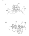
- the average diameter of soot aggregate particles in exhaust gases is about 0.1 ⁇ m.
- the diameter of the supported catalyst particles 202 tends to be much larger than the diameter of the soot aggregate particles 201 as shown in Fig. 1(a) . Accordingly, this prior art has a problem that, due to few contact points 203 between the catalyst particles and the soot aggregate particles, soot combustion behavior by active oxygen induced by an oxide catalyst cannot be fully exerted. Accordingly, soot captured by the catalyst supporting honeycomb is difficult to be oxidized, except for by forced regeneration using high temperature exhaust gases.
- an aim of the present invention is to keep the amount of soot that accumulates with time on cell walls small in catalyst supporting honeycombs in which a catalyst is supported, by allowing soot that has been deposited on and in the cell walls to more easily establish good contact with the catalyst so as to improve the soot combustion behavior by active oxygen provided by the oxide catalyst.
- oxide catalyst particles are supported on a pillar-shaped honeycomb structured body in which a plurality of cells are formed in parallel with one another in a longitudinal direction with a cell wall interposed therebetween, the plurality of cells comprising a set of large-volume cells in which either end of each of the cells is sealed, and a set of small-volume cells in which the other end of each of the cells is sealed, the total area of the set of large-volume cells in the cross section perpendicular to the longitudinal direction being larger than the total area of the set of small-volume cells in the cross section perpendicular to the longitudinal direction.
- the average particle diameter of the oxide catalyst particles is set to 0.05 to 1.00 ⁇ m.
- the average particle diameter of the oxide catalyst particles supported on the honeycomb structured body is set to 0.05 to 1.00 ⁇ m, which is almost the same as an average particle diameter of the soot aggregate particles. Therefore, the contact points between the soot aggregate particles and the catalyst particles can be increased as shown in Fig. 1(b) . In other words, the soot and the catalyst can easily contact with each other, with the result that the soot combustion behavior by active oxygen provided by the oxide catalyst can be improved. This behavior, in addition to the forced regeneration of soot flowed into the catalyst supporting honeycomb, makes it easier to combust soot as compared to the catalyst supporting honeycomb of Patent Document 1.
- soot and the catalyst can more easily contact with each other, by making the set of cells on the exhaust gas inlet side larger than the set of cells on the exhaust gas outlet side to enlarge the area of cell walls on which soot is to be accumulated per unit volume of the catalyst supporting honeycomb. As a result, it is possible to keep the amount of soot that accumulates with time on cell walls small.
- the honeycomb structured body may comprise a ceramic sintered body as the catalyst supporting honeycomb described in claim 3. Further, it is possible to form a honeycomb structured body that is superior in heat resistance, when the honeycomb structured body comprises a silicon carbide sintered body as the catalyst supporting honeycomb described in claim 4. Comprising a silicon carbide also makes the honeycomb structured body superior in mechanical characteristics and high in thermal conductivity. Furthermore, the honeycomb structured body may comprise a plurality of honeycomb units bound together as the catalyst supporting honeycomb described in claim 5.
- the oxide catalyst is at least one member selected from the group consisting of CeO 2 , ZrO 2 , FeO 2 , Fe 2 O 3 , CuO, CuO 2 , Mn 2 O 3 , MnO, K 2 O, and a composite oxide represented by a composition formula A n B 1-n CO 3 (in which A represents La, Nd, Sm, Eu, Gd or Y; B represents an alkali metal or an alkali earth metal; and C represents Mn, Co, Fe or Ni) as the catalyst supporting honeycomb described in claim 6, a catalyst which is excellent in active oxygen delivery performance can be supported on the catalyst supporting honeycomb. As a result of this, the soot combustion function of the catalyst supporting honeycomb can be especially improved.
- the catalyst supporting honeycomb in which the oxide catalyst particles are supported on the cell walls, can show the same effects as those specifically described above as the effects of the catalyst supporting honeycombs according to the catalyst supporting honeycombs described in claims 1 to 6.
- the method of manufacturing the catalyst supporting honeycomb which includes processes of: manufacturing a honeycomb structured body configured by a plurality of cells formed in parallel with one another in a longitudinal direction with a cell wall interposed therebetween, the plurality of cells comprising a set of large-volume cells in which either end of each of the cells is sealed, and a set of small-volume cells in which the other end of each of the cells is sealed, and the total area of the set of large-volume cells in the cross section perpendicular to the longitudinal direction being larger than the total area of the set of small-volume cells in the cross section perpendicular to the longitudinal direction; dispersing a solution of a precursor of a catalyst in a gas; flowing a gas containing the dispersed solution of the precursor of the catalyst into the honeycomb structured body; and heating the honeycomb structured body so that the precursor of the catalyst is formed into catalyst particles.
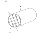
- Fig. 2 is a perspective view that schematically shows one example of the catalyst supporting honeycomb of the first embodiment of the present invention.
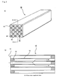
- Fig. 3 (a) is a perspective view of a honeycomb unit that constitutes the catalyst supporting honeycomb shown in Fig. 2
- Fig. 3(b) is an A-A line cross-sectional view of the honeycomb unit shown in Fig. 3 (a) .
- the catalyst supporting honeycomb shown in Fig. 2 comprises a plurality of honeycomb units bound together.
- a honeycomb structured body of the present embodiment may comprise one honeycomb unit as described later.
- a honeycomb structured body 45 a plurality of honeycomb units comprising silicon carbide sintered body and the like are combined with one another by interposing a sealing material layer (adhesive layer) 41 to form a round pillar-shaped ceramic block, and a sealing material layer (coat layer) 42 is further formed on the periphery of this ceramic block. Then, the oxide catalyst particles (not shown) are supported on the honeycomb structured body 45 to obtain a catalyst supporting honeycomb 40.
- a large number of cells 51 are longitudinally disposed in parallel with one another as shown in Figs. 3 (a) and 3 (b) , and a cell wall (wall portion) 53 separating the cells 51 functions as a filter. Namely, either end on the exhaust gas inlet side or the exhaust gas outlet side of each of the cells 51 disposed in the honeycomb unit 50 is sealed with a plug 52, and exhaust gases having flowed into one of the cells 51 surely passes through the cell wall 53 that separates the cells 51, and flows out from another cell 51.
- a cell in the set of large-volume cells in the cross section perpendicular to the longitudinal direction is an octagon
- a cell in the set of small-volume cells in the cross section perpendicular to the longitudinal direction is a quadrangle.
- the oxide catalyst particles having the average particle diameter of 0.05 to 1.00 ⁇ m are supported on the honeycomb unit 50.
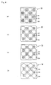
- Figs. 4(a) to 4(d) and Figs. 5(a) to 5(f) are cross-sectional diagrams that schematically show part of the cross section of a honeycomb unit 50 configuring the catalyst supporting honeycomb 40 according to the embodiment of the present invention.
- the aperture ratio (opening ratio) is almost 1.55 in Fig. 4(a) , almost 2.54 in Fig. 4(b) , almost 4.45 in Fig. 4(c) , and almost 6.00 in Fig. 4(d) .
- the aperture ratios are all almost 4.45 in Figs. 5(a), 5(c), and 5(e)
- the aperture ratios are all almost 6.00 in Figs. 5(b), 5(d), and 5(f) .
- the aperture ratio is almost 3.00.
- each of the cross-sectional shapes of the large-volume cells 54 is an octagon and each of the cross-sectional shapes of the small-volume cells 55 is a quadrangle (square), and these are alternately arranged; thus, by changing the cross-sectional area of each of the small-volume cells 55, with the cross-sectional shape of each of the large-volume cells 54 being slightly changed, it is possible to desirably change the aperture ratio easily.
- the aperture ratio can be desirably changed.
- each of the cross-sectional shapes of the large-volume cells 54 is a pentagon with three corners thereof being set to almost right angles; and each of the cross-sectional shapes of the small-volume cells 55 is a quadrangle, and the respective quadrangles are placed at portions diagonally facing each other within a greater quadrangle.
- Honeycomb units shown in Figs. 5 (c) and 5 (d) have modified shapes of the cross-sections shown in Figs.
- This curvature may be desirably set.
- the curved line which forms the cell wall commonly possessed by each of the large-volume cells 54 and each of the small-volume cells 55, corresponds to a quarter of a circle.
- the cross-sectional shapes of the large-volume cells 54 and the small-volume cells 55 are quadrangular (rectangular), and as shown in the Figures, the cross-sectional shapes of two large-volume cells 54 and two small-volume cells 55 are arranged to form almost a square when combined with one another.
- the distance between centers of gravity of cross sections perpendicular to the longitudinal direction of adjacently located large-volume cells 54 is desirably designed to be equal to the distance between centers of gravity of cross sections perpendicular to the longitudinal direction of adjacently located small-volume cells 55.
- the shape of the cells (large-volume cells 54 and small-volume cells 55) in the cross sections perpendicular to the longitudinal direction is desirably a polygonal shape, and more desirably a quadrangle and an octagon.
- the polygonal shape is allowed to exert either of the following effects; this polygonal shape eliminates portions of cells that cause greater friction due to the shape of the cells when exhaust gases pass through the large-volume cells 54 and the small-volume cells 55, so as to reduce a pressure loss caused by the friction of exhaust gases upon passing through the cell, or eliminates portions of a cell wall with irregular thickness, that is, portions that locally make it difficult for exhaust gases to pass through, so as to reduce a pressure loss caused by resistance of a cell wall exerted when exhaust gases pass through the cell wall.
- a polygonal shape of a quadrangle or more is desirably used, and at least one of the corners is desirably formed as an obtuse angle.
- At least one of angles formed by crossing of the cell wall commonly possessed by a large-volume cell 54 and the adjacent large-volume cell 54, and the cell wall commonly possessed by a large-volume cell 54 and a small-volume cell 55 is desirably an obtuse angle.
- the vicinity of each of corners in the cross sections of at least one of the large-volume cells 54 and the small-volume cells 55 is desirably formed by a curved line, as shown in Figs. 5 (c) and 5 (d) , for example. This is because it becomes possible to prevent occurrence of cracks that are caused by a stress concentrating on corners of the cells.
- the ratio of the areas between the set of large-volume cells and the set of small-volume cells in the cross section is desirably 1.01 to 6.0.
- the capacity of the set of small-volume cells becomes too small; thus, the pressure loss, which is caused by the friction of exhaust gases upon passing through the cell on the gas outlet side and resistance exerted on exhaust gases upon passing through the cell wall, increases and thus the initial pressure loss increases.
- the ratio of the areas (“set of large-volume cells"/"set of small-volume cells”) is desirably 1.2 to 5.0. More desirably, the ratio of the areas ("set of large-volume cells"/"set of small-volume cells”) is 1.2 to 3.0.
- the ratio of the areas of the large-volume cell 54 and the small-volume cell 55 in the cross section is desirably 1.01 to 6.0.
- the ratio of the areas (“large-volume cell”/"small-volume cell”) is referred to as an aperture ratio.
- the aperture ratio exceeds 6.0, the capacity of the small-volume cell 55 becomes too small; thus, the pressure loss, which is caused by friction of exhaust gases upon passing through the cell on the gas outlet side and resistance exerted on exhaust gases upon passing through the cell wall, increases and thus the initial pressure loss increases.
- the aperture ratio is desirably 1.2 to 5.0. More desirably, the aperture ratio is 1.2 to 3.0.
- the honeycomb structured body 45 comprises a porous ceramic, and examples of the materials thereof include: a nitride ceramic such as aluminum nitride, silicon nitride and boron nitride; a carbide ceramic such as silicon carbide and zirconium carbide; and an oxide ceramic such as cordierite, alumina, silica and aluminum titanate, and the like.
- the honeycomb structured body 45 may be made of two or more kinds of materials such as a composite material of silicon and silicon carbide. In the case of using a composite material of silicon and silicon carbide, silicon is desirably added thereto to make up 5 to 45% by weight of the entire body.
- a silicon carbide-based ceramic is desirably used, since this material does not melt in the regeneration process due to its superior heat resistance, and is also superior in mechanical characteristics and has a high thermal conductivity.
- the silicon carbide-based ceramic refers to a material having a silicon carbide content of 60% by weight or more.
- the sealing material layer (adhesive layer) 41 which is formed between the honeycomb units 50, also functions as an adhesive material used for binding a plurality of honeycomb units 50 to one another.
- the sealing material layer (coat layer) 42 which is formed on the peripheral face of the ceramic block, is also allowed to function as a sealing material used for preventing exhaust gases passing through the cells from leaking from the peripheral face of the honeycomb structured body 45 when the honeycomb structured body 45 is placed in an exhaust passage of an internal combustion engine, and also to function as an reinforcing member for adjusting the shape of the honeycomb structured body 45.
- the adhesive layer 41 and the coat layer 42 may be formed by using the same material, or may be formed by using different materials.
- the blending ratio of materials thereof may be the same or different.
- the material may have either a dense structure or a porous structure.
- Examples of the material used for forming the adhesive layer 41 and the coat layer 42 include, although not particularly limited, a material comprising at least one of inorganic fibers and inorganic particles in addition to an inorganic binder and an organic binder, may be used.
- Examples of the above-mentioned inorganic binder include silica sol, alumina sol and the like. Each of these materials may be used alone, or two or more kinds of these may be used in combination. Among the above-mentioned inorganic binders, silica sol is more desirably used.
- organic binder examples include polyvinyl alcohol, methyl cellulose, ethyl cellulose, carboxymethyl cellulose and the like. Each of these may be used alone or two or more kinds of these may be used in combination. Among the above-mentioned organic binders, carboxymethyl cellulose is more desirably used.
- the inorganic fibers include a ceramic fiber such as silica-alumina, mullite, alumina and silica, and the like. Each of these may be used alone, or two or more kinds of these may be used in combination. Among the above-mentioned inorganic fibers, silica-alumina fibers are more desirably used.
- the inorganic particles include carbides, nitrides and the like, and more specifically include inorganic powder and the like made of silicon carbide, silicon nitride, boron nitride and the like. Each of these may be used alone, or two or more kinds of these may be used in combination. Among the above-mentioned inorganic particles, silicon carbide, which is superior in thermal conductivity, is more desirably used.
- the particle diameter of the ceramic powder is not particularly limited, the ceramic powder that tends not to cause the case where the size of the honeycomb unit manufactured by the following firing treatment becomes smaller than that of the ceramic molded body after degreased is desirable.
- Binder and dispersant solution may be blended in the above-mentioned raw material.
- the above-mentioned binder include: methyl cellulose, carboxymethyl cellulose, hydroxyethyl cellulose, polyethylene glycol and the like, although not particularly limited thereto.
- the compounding amount of the above-mentioned binder is desirably 1 to 15 parts by weight with respect to 100 parts by weight of ceramic powder.
- dispersant solution examples include: an organic solvent such as benzene; alcohol such as methanol; water and the like, although not particularly limited thereto.
- the ceramic powder, binder and dispersant solution are mixed by an attritor or the like, sufficiently kneaded by a kneader or the like so that a raw material paste is obtained, and then the obtained raw material paste is extrusion molded.
- a molding auxiliary may be added to the raw material paste, if necessary.
- the molding auxiliary include ethylene glycol, dextrin, fatty acid, fatty acid soap, polyvinyl alcohol, water and the like, although not particularly limited thereto.
- a pore-forming agent such as balloons that are fine hollow spheres comprising an oxide-based ceramic, spherical acrylic particles, and graphite may be added to the raw material paste, if necessary.
- balloons not particularly limited, for example, alumina balloons, glass micro-balloons, shirasu balloons, fly ash balloons (FA balloons), mullite balloons and the like may be used. Among these, alumina balloons are more desirably used.
- the above-mentioned ceramic molded body is dried by using a micro-wave dryer, a hot-air dryer, a dielectric dryer, a decompression dryer, a vacuum dryer, a freeze dryer or the like to form a ceramic dried body.
- a predetermined amount of plug material paste, which forms plugs is injected into ends on the side of either set of cells and into the ends on the other side of the other set of cells, so as to seal the cells.
- the plug material paste is not particularly limited, and for example, the same paste as the raw material paste used for manufacturing a ceramic molded body may be used.
- the ceramic dried body filled with the plug material paste is subject to degreasing (e.g. at 200 to 500°C) and firing (e.g. at 1400 to 2300°C) processes under predetermined conditions, so that a honeycomb unit 50, made of a porous ceramic and comprising a single ceramic sintered body as a whole, is manufactured.
- degreasing and firing conditions and the like of the ceramic dried body it is possible to apply conditions that have been conventionally used for manufacturing a honeycomb unit made of a porous ceramic.
- an adhesive paste which is to be the adhesive layer 41, is uniformly applied to a side face of the honeycomb unit 50 to form an adhesive paste layer thereon, and another honeycomb unit 50 is successively laminated on this adhesive paste layer.
- an aggregate of the honeycomb units of a predetermined size is manufactured. Since the material forming the adhesive paste has already been described, the description thereof is omitted here.
- honeycomb unit aggregate is then heated so that the adhesive paste layer is dried and solidified to form the adhesive layer 41. Thereafter, a cutting process is carried out on the honeycomb unit aggregate that a plurality of honeycomb units 50 are bound together by interposing the adhesive layer 41, by using a diamond cutter or the like to form a round pillar-shaped ceramic block.
- the sealing material layer (coat layer) 42 is formed on the periphery of the ceramic block by using the sealing material paste, so as to be able to manufacture a honeycomb structured body 45, having the sealing material layer (coat layer) 42 formed on the periphery of the round pillar-shaped ceramic block in which a plurality of honeycomb units 50 are bound together by interposing the adhesive layer 41. Thereafter, an oxide catalyst particles are supported on the honeycomb structured body 45 so that a catalyst supporting honeycomb 40 is manufactured.
- a solution of a precursor of a catalyst is prepared.
- the precursor of the catalyst include those that become any of CeO 2 , ZrO 2 , FeO 2 , Fe 2 O 3 , CuO, CuO 2 , Mn 2 O 3 , MnO, K 2 O, and a composite oxide represented by a composition formula A n B 1-n CO 3 (in which A represents La, Nd, Sm, Eu, Gd or Y; B represents an alkali metal or an alkali earth metal; and C represents Mn, Co, Fe or Ni), after such precursors are condensed, thermally decomposed, and crystallized in the later process.
- A represents La, Nd, Sm, Eu, Gd or Y
- B represents an alkali metal or an alkali earth metal
- C represents Mn, Co, Fe or Ni
- nitrate salt, carbonate salt, acetate salt and the like containing a metal element of the oxide can be used, and the examples thereof include a metal complex body represented by a general formula M(OR 1 ) p (R 2 COCHCOR 3 ) q (in the formula, M represents one member selected from the group consisting of Ce, Zr, Fe, Cu, Mn and K; p and q each represents an integer number determined so that the metal complex has a 2 to 8 coordinate structure, and either p or q may be 0; when the number of each of R 1 , R 2 and R 3 is two or more, then R 1 , R 2 , R 3 may be respectively the same or different.
- M represents one member selected from the group consisting of Ce, Zr, Fe, Cu, Mn and K
- p and q each represents an integer number determined so that the metal complex has a 2 to 8 coordinate structure, and either p or q may be 0; when the number of each of R 1 , R 2 and R 3 is two
- R 1 and R 2 each represents an alkyl group having 1 to 6 carbon atoms
- R 3 represents an alkyl group having 1 to 6 carbon atoms and/or an alkoxy group having 1 to 16 carbon atoms), and the like.
- solvent include water, an organic solvent such as toluene and alcohol, and the like.
- the above-mentioned solution is dispersed in a gas by a known spraying method and the like.
- the dispersion is carried out in such a manner that the dispersed droplets have a constant size, then the particle diameter of the oxide catalyst particles to be supported on the honeycomb structured body 45 in a later process can be adjusted to a constant size.
- the gas including the dispersed solution of the precursor is transported by a carrier gas to flow into one of the ends of the honeycomb structured body 45.
- the influx speed of the carrier gas is preferably almost the same as the speed of actual exhaust gases from an engine and maybe, for example, about 72000 (1/h) in terms of space velocity.
- the carrier gas is flowed into one of the ends of the honeycomb structured body and flowed out from the adjacent cell after passing through a cell wall (see the arrows in Fig. 3(b) ).
- the solution of the precursor dispersed and mixed in the carrier gas is adhered to the cell walls 53 of the honeycomb structured body 45.
- the precursor of the catalyst attached to the cell walls 53 is condensed, thermally decomposed and crystallized, and is supported on the honeycomb structured body as an oxide catalyst.
- the oxide catalyst is supported preferably in such a manner that the carrier gas is flowed into the honeycomb structured body 45 while the honeycomb structured body 45 is heated so that adhesion of the solution of the precursor as well as condensation, thermal decomposition and crystallization of the precursor are performed simultaneously. With this arrangement, the precursor of the catalyst is adhered to the honeycomb structured body 45 as catalyst particles, and thus tends to be more evenly supported.
- the honeycomb structured body 45 may be an integral honeycomb structured body comprising a single honeycomb unit.
- an integral honeycomb structured body can be formed by using the same method as the above-described method of manufacturing the honeycomb unit, except that the size of a honeycomb molded body to be molded through the extrusion-molding process is larger than in a case where the honeycomb unit is manufactured and that the shape of a honeycomb molded body to be molded through the extrusion-molding process is different from in a case where the honeycomb unit is manufactured.
- cordierite and aluminum titanate which are superior in thermal impact resistance, are desirably used.
- Fig. 6 is a cross-sectional view that schematically shows the cross section of an integral catalyst supporting honeycomb according to the present embodiment.
- a honeycomb structured body 60 shown in Fig. 6 a quadrangular-shaped small-volume cell 55 is formed at each of portions corresponding to crossing points of grid lines, and each large-volume cell 54 has a quadrangular shape with four corners chipped with small quadrangles, and a cell wall (wall portion) 53 separating these are formed.
- the shapes of cells in the raw molded body were formed by using a dice that makes an octagonal shape for a cell in the set of large-volume cells in the cross section perpendicular to the longitudinal direction, and a quadrangular shape for a cell in the set of small-volume cells in the cross section perpendicular to the longitudinal direction, as shown in Fig. 3 .
- the ratio of the cross-sectional area of the set of large-volume cells between that of the set of small-volume cells in the cross sections perpendicular to the longitudinal direction, and the ratio of the cross-sectional area of the large-volume cell between that of small-volume cell in the cross sections perpendicular to the longitudinal direction were both set to 2.54.
- the raw molded body was dried by using a microwave drying apparatus and the like to form a ceramic dried body, followed by filling of a plug material paste having the same composition as that of the raw molded body into the predetermined cells. Further, after again dried by a drying apparatus, the resulting product was degreased at 400°C and then fired at 2200°C under a normal-pressure argon atmosphere for 3 hours so as to manufacture a honeycomb structured body formed by a silicon carbide sintered body with a porosity of cell walls of 42%, an average pore diameter of 11.0 ⁇ m, a size of 34 mm x 34 mm x 150 mm, the number of cells of 45.6 pcs/cm 2 (300 cpsi) and a thickness of the cell walls of 0.25 mm.
- an oxide catalyst was supported on the obtained honeycomb structured body.
- cerium nitrate was dissolved in water to prepare a solution of a precursor of CeO 2 .
- a gas in which the solution of the precursor was dispersed was transported by a carrier gas so as to be flowed into the set of large-volume cells from one of the ends of the honeycomb structured body.
- the speed of the carrier gas was adjusted to a space velocity of 72000 (1/h).
- a catalyst supporting honeycomb in which CeO 2 having an average particle diameter of 0.1 ⁇ m are supported on the honeycomb structured body comprising silicon carbide sintered body was obtained.
- the amount of the CeO 2 was adjusted to 20 g per 1L of the catalyst supporting honeycomb. Measurement of the average particle diameter of the oxide catalyst was performed by using SEM photographs.
- a honeycomb structured body comprising silicon carbide sintered body was manufactured in the same manner as Example 1.
- the honeycomb structured body was immersed in a solution containing 10 g of CeO 2 , 40 ml of water and a pH adjusting agent mixed therein for 5 minutes, and a firing treatment was carried out on the resulting honeycomb structured body at 500°C so that a catalyst supporting honeycomb having CeO 2 supported thereon was manufactured.
- the average particle diameter of the supported CeO 2 was 2 ⁇ m, and the support amount was 20g/L.
- a catalyst supporting honeycomb was manufactured by the same method as in Example 1 except that the cross-sectional shape of every cell was set to a square, as shown in Fig. 7 .
- a catalyst supporting honeycomb was manufactured by the same method as in Comparative Example 1 except that the cross-sectional shape of every cell was set to a square, as shown in Fig. 7 .
- the honeycomb structured body obtained in Example 1 was used as the sample in Comparative Example 4 (no catalyst is supported).
- the honeycomb structured body obtained in Comparative Example 2 was used as the sample in Comparative Example 5 (no catalyst is supported).
- soot generating device CAST2 manufactured by Matter Engineering AG 2.0g/L of soot having an average particle diameter of 82 ⁇ m was captured with each of the catalyst supporting honeycombs and samples obtained in Example 1 and Comparative Examples 1 to 5, at a flow rate of 30 L/min.
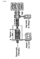
- the catalyst supporting honeycomb having the soot accumulated therein is set in the soot oxidization rate evaluation device of Fig. 8 , and the influx gas temperature is adjusted so that the temperature of the portion that is 15 mm inward from the entry of the sample becomes 560°C while introducing only a nitrogen gas.
- the bulb After having kept the stable state for 10 minutes, the bulb was switched and 10% of oxygen was introduced into the catalyst supporting honeycomb at a space velocity of 72000 (1/h) to combust the soot.
- the concentration of the carbon monoxide and the carbon dioxide generated at the time of combustion was calculated with the CO/CO 2 Analyzer manufactured by Shimadzu Corp., and these were presumed to be the ideal gas to calculate the weight of oxidized soot, so that the soot oxidation rate was obtained.
- the result is shown in Fig. 9 as the change in the amount of oxidized soot accumulated with time per unit time.
- honeycomb structured bodies honeycomb units obtained in Example 1 were combined with each other, and after being dried at 120°C, this was cut by using a diamond cutter to form a round pillar-shaped ceramic block with the thickness of the sealing material layer of 1 mm.
- a sealing material paste (coat layer paste) containing 23.3% by weight of silica-alumina fibers having an average fiber length of 100 ⁇ m and an average fiber diameter of 10 ⁇ m, 30.2% by weight of silicon carbide powders having an average particle diameter of 0. 3 ⁇ m, 7% by weight of silica sol, 0.5% by weight of carboxymethyl cellulose and 39% by weight of water, a sealing material layer having a thickness of 0.2 mm was formed on the peripheral portion of the ceramic block, and this was dried at 120°C to obtain a round pillar-shaped honeycomb structured body having a size of ⁇ 143.8 mm ⁇ 150 mm.
- an oxide catalyst was supported on the honeycomb structured body in the same manner as in Example 1.
- the average particle diameter of CeO 2 was 0.1 ⁇ m, and the support amount was 20 g/L.
- the round pillar-shaped honeycomb structured body obtained in Example 2 was used as the sample in Comparative Example 6 (no catalyst is supported).
- honeycomb structured body honeycomb unit obtained in Comparative Example 2 and the adhesive paste and the sealing material paste (coat layer paste) used in Example 2 .
- a round pillar-shaped honeycomb structured body having a size of ⁇ 143.8 mm ⁇ 150 mm was similarly obtained.
- an oxide catalyst was supported on the honeycomb structured body in the same manner as in Example 1.
- the average particle diameter of CeO 2 was 0.1 ⁇ m, and the support amount was 20 g/L.
- the honeycomb structured body obtained in Comparative Example 7 was used as the sample in Comparative Example 8 (no catalyst is supported).
- catalyst supporting honeycombs and samples obtained in Example 2 and Comparative Examples:6 to 8 were mounted at the position 0.6 m away from the turbo charger of the engine, after having pre-measured the initial weight. Then, the engine was driven in NEDC mode for 30 cycles continuously, and by measuring the weight of the filters (the catalyst supporting honeycombs and samples) again, the amount of soot accumulated in the catalyst supporting honeycombs and samples during the 30 cycles. The obtained results are shown in Fig. 10 with the index of continuous regeneration performance. This index of continuous regeneration performance is defined as the number of cycles by the time 1.0 g/L of soot accumulates in a catalyst supporting honeycomb.
- Fig. 9 (Example 1 and Comparative Examples 1 to 5) indicate that the contact points of catalysts and soot increases and the oxidization rate of soot can be improved exponentially, by providing the set of large-volume cells and the set of small-volume cells and supporting 0.05 to 1 ⁇ m of oxide catalysts on the cell walls.
- Fig. 10 (Example 2 and Comparative Examples 6 to 8) indicate that the continuous regeneration performance is improved and the amount of soot that accumulates with time on the cell walls can be kept small, by providing the set of large-volume cells and the set of small-volume cells and supporting 0.05 to 1 ⁇ m of oxide catalysts on the cell walls.
- Fig. 11 is a photograph that shows the cross section of a cell wall of the catalyst supporting honeycomb in Example 1 observed by SEM. It shows the oxide catalysts supported on the surface of the cell walls in a cake state.
Landscapes
- Chemical & Material Sciences (AREA)
- Engineering & Computer Science (AREA)
- Chemical Kinetics & Catalysis (AREA)
- Materials Engineering (AREA)
- Organic Chemistry (AREA)
- Combustion & Propulsion (AREA)
- Mechanical Engineering (AREA)
- General Engineering & Computer Science (AREA)
- Health & Medical Sciences (AREA)
- Biomedical Technology (AREA)
- Environmental & Geological Engineering (AREA)
- Analytical Chemistry (AREA)
- General Chemical & Material Sciences (AREA)
- Oil, Petroleum & Natural Gas (AREA)
- Catalysts (AREA)
- Exhaust Gas Treatment By Means Of Catalyst (AREA)
Priority Applications (1)
| Application Number | Priority Date | Filing Date | Title |
|---|---|---|---|
| EP10191677A EP2286912A3 (de) | 2007-04-17 | 2008-04-16 | Katalysatorträgerwabe und Verfahren zu ihrer Herstellung |
Applications Claiming Priority (1)
| Application Number | Priority Date | Filing Date | Title |
|---|---|---|---|
| PCT/JP2007/058376 WO2008129671A1 (ja) | 2007-04-17 | 2007-04-17 | 触媒担持ハニカムおよびその製造方法 |
Related Child Applications (1)
| Application Number | Title | Priority Date | Filing Date |
|---|---|---|---|
| EP10191677.3 Division-Into | 2010-11-18 |
Publications (3)
| Publication Number | Publication Date |
|---|---|
| EP2008712A2 true EP2008712A2 (de) | 2008-12-31 |
| EP2008712A3 EP2008712A3 (de) | 2009-04-08 |
| EP2008712B1 EP2008712B1 (de) | 2011-01-26 |
Family
ID=39872838
Family Applications (2)
| Application Number | Title | Priority Date | Filing Date |
|---|---|---|---|
| EP08007430A Active EP2008712B1 (de) | 2007-04-17 | 2008-04-16 | Katalysatorträgerwabe |
| EP10191677A Withdrawn EP2286912A3 (de) | 2007-04-17 | 2008-04-16 | Katalysatorträgerwabe und Verfahren zu ihrer Herstellung |
Family Applications After (1)
| Application Number | Title | Priority Date | Filing Date |
|---|---|---|---|
| EP10191677A Withdrawn EP2286912A3 (de) | 2007-04-17 | 2008-04-16 | Katalysatorträgerwabe und Verfahren zu ihrer Herstellung |
Country Status (6)
| Country | Link |
|---|---|
| US (1) | US7867944B2 (de) |
| EP (2) | EP2008712B1 (de) |
| KR (1) | KR100962450B1 (de) |
| CN (1) | CN101288854B (de) |
| AT (1) | ATE496690T1 (de) |
| WO (1) | WO2008129671A1 (de) |
Families Citing this family (17)
| Publication number | Priority date | Publication date | Assignee | Title |
|---|---|---|---|---|
| WO2004024294A1 (ja) | 2002-09-13 | 2004-03-25 | Ibiden Co., Ltd. | フィルタ |
| US7316722B2 (en) * | 2002-09-13 | 2008-01-08 | Ibiden Co., Ltd. | Honeycomb structure |
| ES2302299T3 (es) * | 2003-06-05 | 2008-07-01 | Ibiden Co., Ltd. | Cuerpo con estructura de panal. |
| WO2005002709A1 (ja) | 2003-06-23 | 2005-01-13 | Ibiden Co., Ltd. | ハニカム構造体 |
| CN101374590B (zh) * | 2006-10-05 | 2011-12-21 | 揖斐电株式会社 | 蜂窝结构体 |
| WO2008129671A1 (ja) | 2007-04-17 | 2008-10-30 | Ibiden Co., Ltd. | 触媒担持ハニカムおよびその製造方法 |
| JP2011052919A (ja) * | 2009-09-03 | 2011-03-17 | Ngk Insulators Ltd | 蓄熱体 |
| CN102470310B (zh) * | 2009-10-08 | 2014-07-23 | 揖斐电株式会社 | 废气净化装置和废气净化方法 |
| JP6219796B2 (ja) * | 2014-09-04 | 2017-10-25 | 日本碍子株式会社 | ハニカムフィルタ |
| CN105626207B (zh) * | 2014-10-16 | 2018-02-16 | 湖北汽车工业学院 | 一种柴油车尾气颗粒物捕集催化器 |
| WO2016076035A1 (ja) * | 2014-11-10 | 2016-05-19 | 日本碍子株式会社 | 蓄熱材を収容する容器 |
| WO2017151975A1 (en) * | 2016-03-02 | 2017-09-08 | Watlow Electric Manufacturing Company | Bare heating elements for heating fluid flows |
| MX2018012815A (es) | 2016-04-22 | 2019-09-04 | Corning Inc | Estructuras de panal de salida rectangular, filtros de material particulado, dados de extrusión y método de fabricación de los mismos. |
| JP6691811B2 (ja) * | 2016-05-02 | 2020-05-13 | 日本碍子株式会社 | 目封止ハニカム構造体、及び目封止ハニカム構造体の形成方法 |
| CN108952890A (zh) * | 2017-05-22 | 2018-12-07 | 黄毅 | 一种汽车尾气颗粒捕捉器 |
| EP3638404A4 (de) | 2017-06-13 | 2021-03-10 | The Board of Trustees of the Leland Stanford Junior University | Elektrochemische katalysatoren mit erweiterter katalytischer aktivität |
| US11746061B2 (en) | 2018-05-04 | 2023-09-05 | Corning Incorporated | Outlet-coated ceramic honeycomb bodies and methods of manufacturing same |
Citations (3)
| Publication number | Priority date | Publication date | Assignee | Title |
|---|---|---|---|---|
| EP1243335A1 (de) | 1999-11-16 | 2002-09-25 | Ibiden Co., Ltd. | Katalysator und verfahren zu dessen herstellung |
| EP1538133A1 (de) | 2003-06-23 | 2005-06-08 | Ibiden Co., Ltd. | Honigwabenstruktur |
| WO2005121513A1 (de) | 2004-06-08 | 2005-12-22 | Robert Bosch Gmbh | Filtereinrichtung für ein abgassystem einer brennkraftmaschine, sowie verfahren zum herstellen einer solchen filtereinrichtung |
Family Cites Families (30)
| Publication number | Priority date | Publication date | Assignee | Title |
|---|---|---|---|---|
| US4276071A (en) * | 1979-12-03 | 1981-06-30 | General Motors Corporation | Ceramic filters for diesel exhaust particulates |
| JP2693980B2 (ja) * | 1988-11-22 | 1997-12-24 | キャタラー工業株式会社 | 排ガス浄化用触媒の製造方法 |
| US5569633A (en) * | 1994-01-12 | 1996-10-29 | Air Products And Chemicals, Inc. | Ion transport membranes with catalyzed dense layer |
| JP3327054B2 (ja) * | 1995-06-07 | 2002-09-24 | トヨタ自動車株式会社 | 排ガス浄化用触媒 |
| JPH11169668A (ja) * | 1997-12-15 | 1999-06-29 | Sumitomo Electric Ind Ltd | 排ガス浄化装置及びその製造方法 |
| JP2002530175A (ja) | 1998-11-20 | 2002-09-17 | コーニンクレッカ フィリップス エレクトロニクス エヌ ヴィ | コードレス走査ヘッドの充電器を備える超音波診断イメージングシステム |
| DE19922358C1 (de) * | 1999-05-14 | 2001-01-25 | Helmut Swars | Wabenkörper |
| JP4642955B2 (ja) | 1999-06-23 | 2011-03-02 | イビデン株式会社 | 触媒担体およびその製造方法 |
| JP5052717B2 (ja) * | 2001-05-02 | 2012-10-17 | 日本碍子株式会社 | ハニカム構造体、及びそれを用いたハニカムフィルター、コンバーターシステム |
| JP2003010616A (ja) * | 2001-06-29 | 2003-01-14 | Ngk Insulators Ltd | ハニカム構造体 |
| US20030041730A1 (en) * | 2001-08-30 | 2003-03-06 | Beall Douglas M. | Honeycomb with varying channel size |
| JP4120215B2 (ja) * | 2001-12-06 | 2008-07-16 | 松下電器産業株式会社 | 排ガス浄化材用触媒スラリーの調製方法 |
| EP1491249A4 (de) | 2002-03-25 | 2005-04-13 | Ibiden Co Ltd | Filter zur abgasdekontaminierung |
| US7510588B2 (en) | 2002-03-29 | 2009-03-31 | Ibiden Co., Ltd. | Ceramic filter and exhaust gas decontamination unit |
| US7316722B2 (en) | 2002-09-13 | 2008-01-08 | Ibiden Co., Ltd. | Honeycomb structure |
| WO2004024294A1 (ja) | 2002-09-13 | 2004-03-25 | Ibiden Co., Ltd. | フィルタ |
| US20040176246A1 (en) | 2003-03-05 | 2004-09-09 | 3M Innovative Properties Company | Catalyzing filters and methods of making |
| ES2302299T3 (es) | 2003-06-05 | 2008-07-01 | Ibiden Co., Ltd. | Cuerpo con estructura de panal. |
| WO2005002709A1 (ja) | 2003-06-23 | 2005-01-13 | Ibiden Co., Ltd. | ハニカム構造体 |
| DE602004011971T3 (de) | 2003-10-20 | 2012-10-18 | Ibiden Co., Ltd. | Wabenstruktur |
| JP4471621B2 (ja) * | 2003-10-20 | 2010-06-02 | イビデン株式会社 | ハニカム構造体 |
| JP4439236B2 (ja) | 2003-10-23 | 2010-03-24 | イビデン株式会社 | ハニカム構造体 |
| WO2005079165A2 (ja) | 2004-02-23 | 2005-09-01 | Ibiden Co Ltd | ハニカム構造体及び排気ガス浄化装置 |
| WO2006041174A1 (ja) * | 2004-10-12 | 2006-04-20 | Ibiden Co., Ltd. | セラミックハニカム構造体 |
| FR2879236A1 (fr) | 2004-12-09 | 2006-06-16 | Renault Sas | Filtre a particules a section de canaux variable |
| US7855021B2 (en) * | 2004-12-22 | 2010-12-21 | Brookhaven Science Associates, Llc | Electrocatalysts having platium monolayers on palladium, palladium alloy, and gold alloy core-shell nanoparticles, and uses thereof |
| CN1954137B (zh) * | 2005-07-21 | 2011-12-21 | 揖斐电株式会社 | 蜂窝结构体以及废气净化装置 |
| WO2007129430A1 (ja) * | 2006-05-01 | 2007-11-15 | Ibiden Co., Ltd. | ハニカム構造体、ハニカム構造体の製造方法、ハニカムフィルタ及びハニカムフィルタの製造方法 |
| WO2008105082A1 (ja) * | 2007-02-28 | 2008-09-04 | Ibiden Co., Ltd. | ハニカム構造体 |
| WO2008129671A1 (ja) | 2007-04-17 | 2008-10-30 | Ibiden Co., Ltd. | 触媒担持ハニカムおよびその製造方法 |
-
2007
- 2007-04-17 WO PCT/JP2007/058376 patent/WO2008129671A1/ja active Application Filing
-
2008
- 2008-04-11 KR KR1020080033773A patent/KR100962450B1/ko active IP Right Grant
- 2008-04-11 CN CN2008100924447A patent/CN101288854B/zh active Active
- 2008-04-16 AT AT08007430T patent/ATE496690T1/de not_active IP Right Cessation
- 2008-04-16 EP EP08007430A patent/EP2008712B1/de active Active
- 2008-04-16 EP EP10191677A patent/EP2286912A3/de not_active Withdrawn
- 2008-04-16 US US12/104,296 patent/US7867944B2/en active Active
Patent Citations (3)
| Publication number | Priority date | Publication date | Assignee | Title |
|---|---|---|---|---|
| EP1243335A1 (de) | 1999-11-16 | 2002-09-25 | Ibiden Co., Ltd. | Katalysator und verfahren zu dessen herstellung |
| EP1538133A1 (de) | 2003-06-23 | 2005-06-08 | Ibiden Co., Ltd. | Honigwabenstruktur |
| WO2005121513A1 (de) | 2004-06-08 | 2005-12-22 | Robert Bosch Gmbh | Filtereinrichtung für ein abgassystem einer brennkraftmaschine, sowie verfahren zum herstellen einer solchen filtereinrichtung |
Also Published As
| Publication number | Publication date |
|---|---|
| WO2008129671A1 (ja) | 2008-10-30 |
| CN101288854B (zh) | 2012-08-08 |
| EP2008712B1 (de) | 2011-01-26 |
| KR100962450B1 (ko) | 2010-06-14 |
| CN101288854A (zh) | 2008-10-22 |
| KR20080093884A (ko) | 2008-10-22 |
| US7867944B2 (en) | 2011-01-11 |
| EP2008712A3 (de) | 2009-04-08 |
| EP2286912A2 (de) | 2011-02-23 |
| EP2286912A3 (de) | 2011-06-01 |
| US20080261806A1 (en) | 2008-10-23 |
| ATE496690T1 (de) | 2011-02-15 |
Similar Documents
| Publication | Publication Date | Title |
|---|---|---|
| EP2008712B1 (de) | Katalysatorträgerwabe | |
| US7540898B2 (en) | Honeycomb structured body | |
| US7731774B2 (en) | Honeycomb structured body | |
| US7449427B2 (en) | Honeycomb structured body | |
| US7556782B2 (en) | Honeycomb structured body | |
| US8039415B2 (en) | Honeycomb structure | |
| US7517502B2 (en) | Honeycomb structural body | |
| US8283019B2 (en) | Honeycomb structured body | |
| US8038955B2 (en) | Catalyst supporting honeycomb and method of manufacturing the same | |
| US8361400B2 (en) | Honeycomb structural body | |
| US8721979B2 (en) | Honeycomb structure and exhaust gas purifying apparatus | |
| US7833936B2 (en) | Honeycomb structure, method for producing the same, and exhaust emission purification apparatus | |
| JP5270879B2 (ja) | ハニカム構造体 | |
| JP5474311B2 (ja) | 触媒担持ハニカムおよびその製造方法 | |
| JP2006223983A (ja) | ハニカム構造体 | |
| US20070172632A1 (en) | Method for producing porous body, porous body, and honeycomb structure | |
| EP2108448B1 (de) | Wabenkatalysatorkörper | |
| US20120251767A1 (en) | Honeycomb structure | |
| US8414838B2 (en) | Honeycomb filter and exhaust gas purifying apparatus |
Legal Events
| Date | Code | Title | Description |
|---|---|---|---|
| PUAI | Public reference made under article 153(3) epc to a published international application that has entered the european phase |
Free format text: ORIGINAL CODE: 0009012 |
|
| 17P | Request for examination filed |
Effective date: 20080416 |
|
| AK | Designated contracting states |
Kind code of ref document: A2 Designated state(s): AT BE BG CH CY CZ DE DK EE ES FI FR GB GR HR HU IE IS IT LI LT LU LV MC MT NL NO PL PT RO SE SI SK TR |
|
| AX | Request for extension of the european patent |
Extension state: AL BA MK RS |
|
| PUAL | Search report despatched |
Free format text: ORIGINAL CODE: 0009013 |
|
| AK | Designated contracting states |
Kind code of ref document: A3 Designated state(s): AT BE BG CH CY CZ DE DK EE ES FI FR GB GR HR HU IE IS IT LI LT LU LV MC MT NL NO PL PT RO SE SI SK TR |
|
| AX | Request for extension of the european patent |
Extension state: AL BA MK RS |
|
| 17Q | First examination report despatched |
Effective date: 20090720 |
|
| AKX | Designation fees paid |
Designated state(s): AT BE BG CH CY CZ DE DK EE ES FI FR GB GR HR HU IE IS IT LI LT LU LV MC MT NL NO PL PT RO SE SI SK TR |
|
| GRAP | Despatch of communication of intention to grant a patent |
Free format text: ORIGINAL CODE: EPIDOSNIGR1 |
|
| RTI1 | Title (correction) |
Free format text: CATALYST SUPPORTING HONEYCOMB |
|
| GRAS | Grant fee paid |
Free format text: ORIGINAL CODE: EPIDOSNIGR3 |
|
| GRAA | (expected) grant |
Free format text: ORIGINAL CODE: 0009210 |
|
| AK | Designated contracting states |
Kind code of ref document: B1 Designated state(s): AT BE BG CH CY CZ DE DK EE ES FI FR GB GR HR HU IE IS IT LI LT LU LV MC MT NL NO PL PT RO SE SI SK TR |
|
| REG | Reference to a national code |
Ref country code: GB Ref legal event code: FG4D |
|
| REG | Reference to a national code |
Ref country code: CH Ref legal event code: EP |
|
| REG | Reference to a national code |
Ref country code: IE Ref legal event code: FG4D |
|
| REF | Corresponds to: |
Ref document number: 602008004695 Country of ref document: DE Date of ref document: 20110310 Kind code of ref document: P |
|
| REG | Reference to a national code |
Ref country code: DE Ref legal event code: R096 Ref document number: 602008004695 Country of ref document: DE Effective date: 20110310 |
|
| REG | Reference to a national code |
Ref country code: NL Ref legal event code: VDEP Effective date: 20110126 |
|
| LTIE | Lt: invalidation of european patent or patent extension |
Effective date: 20110126 |
|
| PG25 | Lapsed in a contracting state [announced via postgrant information from national office to epo] |
Ref country code: SE Free format text: LAPSE BECAUSE OF FAILURE TO SUBMIT A TRANSLATION OF THE DESCRIPTION OR TO PAY THE FEE WITHIN THE PRESCRIBED TIME-LIMIT Effective date: 20110126 Ref country code: PT Free format text: LAPSE BECAUSE OF FAILURE TO SUBMIT A TRANSLATION OF THE DESCRIPTION OR TO PAY THE FEE WITHIN THE PRESCRIBED TIME-LIMIT Effective date: 20110526 Ref country code: NO Free format text: LAPSE BECAUSE OF FAILURE TO SUBMIT A TRANSLATION OF THE DESCRIPTION OR TO PAY THE FEE WITHIN THE PRESCRIBED TIME-LIMIT Effective date: 20110426 Ref country code: IS Free format text: LAPSE BECAUSE OF FAILURE TO SUBMIT A TRANSLATION OF THE DESCRIPTION OR TO PAY THE FEE WITHIN THE PRESCRIBED TIME-LIMIT Effective date: 20110526 Ref country code: LT Free format text: LAPSE BECAUSE OF FAILURE TO SUBMIT A TRANSLATION OF THE DESCRIPTION OR TO PAY THE FEE WITHIN THE PRESCRIBED TIME-LIMIT Effective date: 20110126 Ref country code: LV Free format text: LAPSE BECAUSE OF FAILURE TO SUBMIT A TRANSLATION OF THE DESCRIPTION OR TO PAY THE FEE WITHIN THE PRESCRIBED TIME-LIMIT Effective date: 20110126 Ref country code: GR Free format text: LAPSE BECAUSE OF FAILURE TO SUBMIT A TRANSLATION OF THE DESCRIPTION OR TO PAY THE FEE WITHIN THE PRESCRIBED TIME-LIMIT Effective date: 20110427 Ref country code: ES Free format text: LAPSE BECAUSE OF FAILURE TO SUBMIT A TRANSLATION OF THE DESCRIPTION OR TO PAY THE FEE WITHIN THE PRESCRIBED TIME-LIMIT Effective date: 20110507 Ref country code: HR Free format text: LAPSE BECAUSE OF FAILURE TO SUBMIT A TRANSLATION OF THE DESCRIPTION OR TO PAY THE FEE WITHIN THE PRESCRIBED TIME-LIMIT Effective date: 20110126 |
|
| PG25 | Lapsed in a contracting state [announced via postgrant information from national office to epo] |
Ref country code: CY Free format text: LAPSE BECAUSE OF FAILURE TO SUBMIT A TRANSLATION OF THE DESCRIPTION OR TO PAY THE FEE WITHIN THE PRESCRIBED TIME-LIMIT Effective date: 20110126 Ref country code: BE Free format text: LAPSE BECAUSE OF FAILURE TO SUBMIT A TRANSLATION OF THE DESCRIPTION OR TO PAY THE FEE WITHIN THE PRESCRIBED TIME-LIMIT Effective date: 20110126 Ref country code: AT Free format text: LAPSE BECAUSE OF FAILURE TO SUBMIT A TRANSLATION OF THE DESCRIPTION OR TO PAY THE FEE WITHIN THE PRESCRIBED TIME-LIMIT Effective date: 20110126 Ref country code: FI Free format text: LAPSE BECAUSE OF FAILURE TO SUBMIT A TRANSLATION OF THE DESCRIPTION OR TO PAY THE FEE WITHIN THE PRESCRIBED TIME-LIMIT Effective date: 20110126 Ref country code: PL Free format text: LAPSE BECAUSE OF FAILURE TO SUBMIT A TRANSLATION OF THE DESCRIPTION OR TO PAY THE FEE WITHIN THE PRESCRIBED TIME-LIMIT Effective date: 20110126 Ref country code: SI Free format text: LAPSE BECAUSE OF FAILURE TO SUBMIT A TRANSLATION OF THE DESCRIPTION OR TO PAY THE FEE WITHIN THE PRESCRIBED TIME-LIMIT Effective date: 20110126 Ref country code: BG Free format text: LAPSE BECAUSE OF FAILURE TO SUBMIT A TRANSLATION OF THE DESCRIPTION OR TO PAY THE FEE WITHIN THE PRESCRIBED TIME-LIMIT Effective date: 20110426 Ref country code: NL Free format text: LAPSE BECAUSE OF FAILURE TO SUBMIT A TRANSLATION OF THE DESCRIPTION OR TO PAY THE FEE WITHIN THE PRESCRIBED TIME-LIMIT Effective date: 20110126 |
|
| PG25 | Lapsed in a contracting state [announced via postgrant information from national office to epo] |
Ref country code: DK Free format text: LAPSE BECAUSE OF FAILURE TO SUBMIT A TRANSLATION OF THE DESCRIPTION OR TO PAY THE FEE WITHIN THE PRESCRIBED TIME-LIMIT Effective date: 20110126 Ref country code: EE Free format text: LAPSE BECAUSE OF FAILURE TO SUBMIT A TRANSLATION OF THE DESCRIPTION OR TO PAY THE FEE WITHIN THE PRESCRIBED TIME-LIMIT Effective date: 20110126 |
|
| PG25 | Lapsed in a contracting state [announced via postgrant information from national office to epo] |
Ref country code: CZ Free format text: LAPSE BECAUSE OF FAILURE TO SUBMIT A TRANSLATION OF THE DESCRIPTION OR TO PAY THE FEE WITHIN THE PRESCRIBED TIME-LIMIT Effective date: 20110126 Ref country code: RO Free format text: LAPSE BECAUSE OF FAILURE TO SUBMIT A TRANSLATION OF THE DESCRIPTION OR TO PAY THE FEE WITHIN THE PRESCRIBED TIME-LIMIT Effective date: 20110126 Ref country code: SK Free format text: LAPSE BECAUSE OF FAILURE TO SUBMIT A TRANSLATION OF THE DESCRIPTION OR TO PAY THE FEE WITHIN THE PRESCRIBED TIME-LIMIT Effective date: 20110126 Ref country code: MC Free format text: LAPSE BECAUSE OF NON-PAYMENT OF DUE FEES Effective date: 20110430 |
|
| PLBE | No opposition filed within time limit |
Free format text: ORIGINAL CODE: 0009261 |
|
| STAA | Information on the status of an ep patent application or granted ep patent |
Free format text: STATUS: NO OPPOSITION FILED WITHIN TIME LIMIT |
|
| PG25 | Lapsed in a contracting state [announced via postgrant information from national office to epo] |
Ref country code: MT Free format text: LAPSE BECAUSE OF FAILURE TO SUBMIT A TRANSLATION OF THE DESCRIPTION OR TO PAY THE FEE WITHIN THE PRESCRIBED TIME-LIMIT Effective date: 20110126 |
|
| 26N | No opposition filed |
Effective date: 20111027 |
|
| REG | Reference to a national code |
Ref country code: IE Ref legal event code: MM4A |
|
| REG | Reference to a national code |
Ref country code: DE Ref legal event code: R097 Ref document number: 602008004695 Country of ref document: DE Effective date: 20111027 |
|
| PG25 | Lapsed in a contracting state [announced via postgrant information from national office to epo] |
Ref country code: IE Free format text: LAPSE BECAUSE OF NON-PAYMENT OF DUE FEES Effective date: 20110416 |
|
| PG25 | Lapsed in a contracting state [announced via postgrant information from national office to epo] |
Ref country code: IT Free format text: LAPSE BECAUSE OF FAILURE TO SUBMIT A TRANSLATION OF THE DESCRIPTION OR TO PAY THE FEE WITHIN THE PRESCRIBED TIME-LIMIT Effective date: 20110126 |
|
| REG | Reference to a national code |
Ref country code: CH Ref legal event code: PL |
|
| GBPC | Gb: european patent ceased through non-payment of renewal fee |
Effective date: 20120416 |
|
| PG25 | Lapsed in a contracting state [announced via postgrant information from national office to epo] |
Ref country code: GB Free format text: LAPSE BECAUSE OF NON-PAYMENT OF DUE FEES Effective date: 20120416 Ref country code: LI Free format text: LAPSE BECAUSE OF NON-PAYMENT OF DUE FEES Effective date: 20120430 Ref country code: CH Free format text: LAPSE BECAUSE OF NON-PAYMENT OF DUE FEES Effective date: 20120430 |
|
| PG25 | Lapsed in a contracting state [announced via postgrant information from national office to epo] |
Ref country code: LU Free format text: LAPSE BECAUSE OF NON-PAYMENT OF DUE FEES Effective date: 20110416 |
|
| PG25 | Lapsed in a contracting state [announced via postgrant information from national office to epo] |
Ref country code: TR Free format text: LAPSE BECAUSE OF FAILURE TO SUBMIT A TRANSLATION OF THE DESCRIPTION OR TO PAY THE FEE WITHIN THE PRESCRIBED TIME-LIMIT Effective date: 20110126 |
|
| PG25 | Lapsed in a contracting state [announced via postgrant information from national office to epo] |
Ref country code: HU Free format text: LAPSE BECAUSE OF FAILURE TO SUBMIT A TRANSLATION OF THE DESCRIPTION OR TO PAY THE FEE WITHIN THE PRESCRIBED TIME-LIMIT Effective date: 20110126 |
|
| REG | Reference to a national code |
Ref country code: FR Ref legal event code: PLFP Year of fee payment: 8 |
|
| REG | Reference to a national code |
Ref country code: FR Ref legal event code: PLFP Year of fee payment: 9 |
|
| REG | Reference to a national code |
Ref country code: FR Ref legal event code: PLFP Year of fee payment: 10 |
|
| REG | Reference to a national code |
Ref country code: FR Ref legal event code: PLFP Year of fee payment: 11 |
|
| PGFP | Annual fee paid to national office [announced via postgrant information from national office to epo] |
Ref country code: FR Payment date: 20230309 Year of fee payment: 16 |
|
| PGFP | Annual fee paid to national office [announced via postgrant information from national office to epo] |
Ref country code: DE Payment date: 20230228 Year of fee payment: 16 |