EP1239499A2 - Elektrischer Drucktastenschalter - Google Patents
Elektrischer Drucktastenschalter Download PDFInfo
- Publication number
- EP1239499A2 EP1239499A2 EP02002535A EP02002535A EP1239499A2 EP 1239499 A2 EP1239499 A2 EP 1239499A2 EP 02002535 A EP02002535 A EP 02002535A EP 02002535 A EP02002535 A EP 02002535A EP 1239499 A2 EP1239499 A2 EP 1239499A2
- Authority
- EP
- European Patent Office
- Prior art keywords
- membrane
- housing
- actuating element
- switch according
- electrical
- Prior art date
- Legal status (The legal status is an assumption and is not a legal conclusion. Google has not performed a legal analysis and makes no representation as to the accuracy of the status listed.)
- Granted
Links
- 239000012528 membrane Substances 0.000 claims abstract description 49
- 238000009434 installation Methods 0.000 claims description 17
- 230000006835 compression Effects 0.000 claims description 14
- 238000007906 compression Methods 0.000 claims description 14
- 238000007789 sealing Methods 0.000 claims description 11
- 230000002093 peripheral effect Effects 0.000 claims description 3
- 238000002347 injection Methods 0.000 claims description 2
- 239000007924 injection Substances 0.000 claims description 2
- 230000005540 biological transmission Effects 0.000 description 3
- 230000035515 penetration Effects 0.000 description 3
- 230000007613 environmental effect Effects 0.000 description 2
- 210000001331 nose Anatomy 0.000 description 2
- 238000005553 drilling Methods 0.000 description 1
- 230000005489 elastic deformation Effects 0.000 description 1
- 210000000887 face Anatomy 0.000 description 1
- 230000002349 favourable effect Effects 0.000 description 1
- 210000003128 head Anatomy 0.000 description 1
- 238000001746 injection moulding Methods 0.000 description 1
- 230000005923 long-lasting effect Effects 0.000 description 1
- 238000004519 manufacturing process Methods 0.000 description 1
- 239000000463 material Substances 0.000 description 1
- 229920001296 polysiloxane Polymers 0.000 description 1
- 230000036316 preload Effects 0.000 description 1
- 230000006641 stabilisation Effects 0.000 description 1
- 238000011105 stabilization Methods 0.000 description 1
Images



Classifications
-
- H—ELECTRICITY
- H01—ELECTRIC ELEMENTS
- H01H—ELECTRIC SWITCHES; RELAYS; SELECTORS; EMERGENCY PROTECTIVE DEVICES
- H01H13/00—Switches having rectilinearly-movable operating part or parts adapted for pushing or pulling in one direction only, e.g. push-button switch
- H01H13/02—Details
- H01H13/04—Cases; Covers
- H01H13/06—Dustproof, splashproof, drip-proof, waterproof or flameproof casings
Definitions
- the invention relates to an electrical push button switch, especially for a motor vehicle, for sealing Installation in an installation space with one in a housing mounted actuator for loading Switch contacts that are connected to a socket in Connect.
- Such a push button switch is usually in a door or a trunk lid of a motor vehicle installed, to switch an assigned lighting on or off.
- the Push button switch is a seal against the installation space, assigned to the body of the motor vehicle, for example, to prevent dirt and moisture from entering To prevent installation space.
- Such a push button switch is however, disadvantageous in that the switch contacts are not in front Dirt and moisture are protected and therefore relative are subject to great susceptibility to faults.
- plastic cover At least the actuator and part of the housing of the push button switch.
- the plastic cover is so between the housing of the push button switch and the installation space clamped that they the Penetration of dirt and moisture inside the Pushbutton switch and in the installation space prevented.
- plastic cover is a variety of mechanical Exposed to other environmental influences and is therefore subject to relatively large wear, with a leak.
- the object is achieved in that Housing between the actuator and the switch contacts a membrane spanning the entire cross section of the housing is arranged, which the switching contacts against the Seals actuator.
- the membrane housed in the housing is subject to only limited conditions Environmental influences and only the mechanical load when actuated by the actuator. This Sizes are relatively easy to determine and constructive Design of the membrane to take into account why this can be designed for a relatively long service life. Furthermore prevents the entire housing cross section spanning membrane that dirt and moisture from the Area of the actuating element in the area of the switch contacts penetration.
- the membrane is expediently made of an elastic Made of plastic.
- the membrane is almost in one Any shape can be produced inexpensively and has the Sealing and power transmission required properties.
- Injection molded membrane in the housing is advantageously advantageous.
- the one-piece production of the membrane and housing can, for example, in the two-component injection molding process done what assembly costs saves.
- the membrane has a circumferential annular groove for receiving a molded shoulder in the housing, which itself below the actuator over the entire circumference of the housing extends.
- the dimensioning of the ring groove and the shoulder is designed so that the annular groove of the membrane the shoulder of the case with some preload encloses what realizes a reliable seal is.
- the membrane can be relatively easy to mount in the housing and can be replaced if necessary.
- the membrane preferably faces two in the area of the actuating element extending webs on a sealing ring wear on the towards the actuator facing end of the housing to seal against the Installation space rests. Because of this measure, it is not required when installing the push button switch in the Installation space to provide an additional sealing ring to the Entry of dirt and / or moisture into the installation space to prevent.
- the diaphragm is preferably acted upon on its surface outer circumference delimited by an annular expansion groove.
- the expansion groove is thus between the circumferential ring groove and the application area arranged and catches the when the actuating element is acted on the membrane acting deformation. Due to the expansion groove neither the contact surface nor the circumferential ring groove a deformation when the actuating element is acted upon, why on the one hand the tightness and on the other hand one relatively long life of the membrane due to a short mechanical load is ensured.
- the switch contacts arranged in domes of a switch mat, the switching mat circumferentially between the base and a peripheral edge of the housing is clamped.
- the complete circumferential clamping usually from one Switch mat made of silicone material prevents penetration of dirt and moisture in the area of Switch contacts from the installation space, i.e. from the direction of Connection contacts of the push button switch.
- the base expediently protrudes into the housing Support for an actuator assigned to the switch contacts Compression spring on, the bearing corresponding Push through openings in the safety mat.
- Compression spring determines the one for actuating the push button switch required acting force and on the other the restoring force for the actuator.
- the face of the membrane assigned to the membrane preferably has Actuator has a raised contact surface for the membrane at least the same diameter as the contact surface Has.
- the actuator For reliable storage of the actuator in the Housing, expediently has the actuating element on the circumferential side Noses on which are longitudinally displaceable in corresponding Engage openings in the housing. It is also preferred the path of the actuator on the one hand through the Striking the lugs on the top of the openings and to others limited by the compressed compression spring.
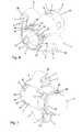
- the push button switch comprises a substantially cylindrical one Housing 1, on the opposite flanges 2 with holes 3 for fastening in an installation space of a motor vehicle are molded. Extend from each flange 2 two spaced webs 4, which are used for stabilization of the flange 2 are molded onto the housing 1. In his in Direction of an actuator 5 facing upper area the housing 1 is provided with elongated openings 6, in the peripheral lugs 7 of the actuating element 5 intervene. The lugs 7 are arranged on clip arms 8.
- the actuating element 5 points into the housing 1 protruding projections 9 arranged between the clip arms 8 for non-rotatable but longitudinally movable storage in one corresponding inner contour of the housing 1 and an over the lower edge of the actuator 5 protruding, in the housing 1 protruding plunger 10.
- a Membrane 11 arranged in the housing 1.
- the membrane 11 is provided with a circumferential annular groove 13, which one extending over the entire circumference of the housing 1 and the inner wall integrally formed shoulder 14 under tension seals.
- One closes the annular groove 13 annular expansion groove 12 from the bottom of the Membrane 11 is embedded in the end face and the Limited outer diameter of an application surface 36.
- the upper edge of the convex expansion groove 12 projects over the upper edge the circumferential annular groove 13.
- the plunger 10 of the actuating element 5 On the exposure surface 36 of the membrane 11 is the plunger 10 of the actuating element 5 on, the outside diameter slightly smaller than the corresponding diameter of the application area 36 is.
- the housing 1 On the side opposite the actuating element 5 the housing 1 has clip openings 15 for latching reception of clip lugs 16 of a housing 1 closing Base 17 on.
- a coded connection collar 18 of the Base 17 extend with a lead frame 19 in connection standing connection contacts 20 of the push button switch.
- a switching mat 21 with domes is located above the lead frame 19 22 provided for receiving switching contacts, not shown. The switching mat 21 is sealing between the circumference the housing 1 and the base 17 clamped.
- the base 17 comprises supports extending into the housing 1 23 for a compression spring 24, the supports 23 corresponding Pass through openings 25 of the switching mat 21.
- a compression spring 24 Around damage to the membrane 11 by the compression spring 24 avoid and at the same time a reliable exposure to ensure the switching contacts overlaps one of the diaphragms 11 associated end face 26 of an actuator 27 die Compression spring 24.
- the actuator 27 is longitudinally displaceable in the Housing 1 mounted, its associated with the membrane 11 Face 26 is aligned parallel to the same.
- the End face 26 of the actuator 27 has a protruding contact surface 37, which is just designed.
- the contact area 37 of the actuator 27 and the loading surface 36 of the Membranes 11 are approximately the same size.
- the push button switch in the alternative embodiment are the flanges formed on the side of the housing 1 2 designed in such a way that they can accommodate metallic Sleeves 28 are used to attach the push button switch be used in the installation space of the motor vehicle.
- the actuating element 5 has arranged between the lugs 7 Guide grooves 29 in which on the one hand guide webs 30th of the housing 1 and on the other molded onto the membrane 11 Take up opposite webs 31.
- the webs 31 of the membrane 11 extend to the corresponding end face of the housing 1 and wear a sealing ring 32 which is used for sealing against the installation space on the assigned end face of the Housing 1 rests.
- the base 17 is provided with centering lugs 33, which in corresponding recesses 34 of the housing 1st intervention. Furthermore, the base 17 has a circumferential one Approach 35 for receiving a sealing ring, not shown for sealing the push button switch on the underside the installation space.
Landscapes
- Push-Button Switches (AREA)
Abstract
Description
- Fig.1
- eine Explosionsdarstellung des erfindungsgemäßen Drucktastenschalters,
- Fig.2
- eine Explosionsdarstellung des erfindungsgemäßen Drucktastenschalters in einer alternativen Ausfüh-rungsform,
- Fig.3
- eine perspektivische Darstellung des Drucktasten-schalters nach Fig. 1,
- Fig.4
- eine weitere perspektivische Darstellung des Druckta-stenschalters nach Fig. 1,
- Fig.5
- eine Darstellung des Drucktastenschalters nach Fig. 1 im Schnitt,
- Fig.6
- eine perspektivische Darstellung des Drucktasten-schalters nach Fig. 2,
- Fig.7
- eine weitere perspektivische Darstellung des Druckta-stenschalters nach Fig. 2 und
- Fig.8
- eine Darstellung des Drucktastenschalters nach Fig. 2 im Schnitt.
- 1.
- Gehäuse
- 2.
- Flansch
- 3.
- Bohrung
- 4.
- Steg
- 5.
- Betätigungselement
- 6.
- Öffnung
- 7.
- Nase
- 8.
- Klipsarm
- 9.
- Vorsprung
- 10.
- Stößel
- 11.
- Membrane
- 12.
- Dehnungsnut
- 13.
- Ringnut
- 14.
- Schulter
- 15.
- Klipsöffnung
- 16.
- Klipsnase
- 17.
- Sockel
- 18.
- Anschlusskragen
- 19.
- Stanzgitter
- 20.
- Anschlusskontakt
- 21.
- Schaltmatte
- 22.
- Dom
- 23.
- Auflager
- 24.
- Druckfeder
- 25.
- Durchbruch
- 26.
- Stirnseite
- 27.
- Betätiger
- 28.
- Hülse
- 29.
- Führungsnut
- 30.
- Führungssteg
- 31.
- Steg
- 32.
- Dichtring
- 33.
- Zentriernase
- 34.
- Ausnehmung
- 35.
- Ansatz
- 36.
- Beaufschlagungsfläche
- 37.
- Kontaktfläche
Claims (13)
- Elektrischer Drucktastenschalter, insbesondere für ein Kraftfahrzeug, zur abgedichteten Montage in einen Einbauraum mit einem in einem Gehäuse (1) gelagerten Betätigungselement (5) zur Beaufschlagung von Schaltkontakten, die mit Anschlusskontakten (20) eines Sockels (17) in Verbindung stehen, dadurch gekennzeichnet , dass in dem Gehäuse (1) zwischen dem Betätigungselement (5) und den Schaltkontakten eine den gesamten Gehäusequerschnitt überspannende Membrane (11) angeordnet ist, die die Schaltkontakte gegenüber dem Betätigungselement (5) abdichtet.
- Elektrischer Drucktastenschalter nach Anspruch 1, dadurch gekennzeichnet, dass die Membrane (11) aus einem elastischen Kunststoff gefertigt ist.
- Elektrischer Drucktastenschalter nach Anspruch 1 oder 2, dadurch gekennzeichnet, dass die Membrane (11) in dem Gehäuse (1) angespritzt ist.
- Elektrischer Drucktastenschalter nach Anspruch 1 oder 2, dadurch gekennzeichnet, dass die Membrane (11) eine umfangsseitige Ringnut (13) zur Aufnahme einer in dem Gehäuse (1) angeformten Schulter (14) aufweist, die sich unterhalb des Betätigungselementes (5) über den gesamten Umfang des Gehäuses (1) erstreckt.
- Elektrischer Drucktastenschalter nach einem der Ansprüche 1 bis 4, dadurch gekennzeichnet, dass die Membrane (11) zwei sich in den Bereich des Betätigungselementes (5) erstreckende Stege (31) aufweist, die einen Dichtring (32) tragen, der auf der in Richtung des Betätigungselementes (5) weisenden Stirnseite des Gehäuses (1) zur Abdichtung gegen den Einbauraum aufliegt.
- Elektrischer Drucktastenschalter nach einem der Ansprüche 1 bis 5, dadurch gekennzeichnet, dass in der Membrane (11) eine ebene Beaufschlagungsfläche (36) für das Betätigungselement (5) ausgeformt ist.
- Elektrischer Drucktastenschalter nach Anspruch 6, d a-durch gekennzeichnet, dass die Beaufschlagungsfläche (36) der Membrane (11) an ihrem äußeren Umfang durch eine ringförmige Dehnungsnut (12) begrenzt ist.
- Elektrischer Drucktastenschalter nach einem der Ansprüche 1 bis 7, dadurch gekennzeichnet, dass die Schaltkontakte in Domen (22) einer Schaltmatte (21) angeordnet sind, wobei die Schaltmatte (21) umfangsseitig zwischen dem Sockel (17) und einem umlaufenden Rand des Gehäuses (1) eingespannt ist.
- Elektrischer Drucktastenschalter nach einem der Ansprüche 1 bis 8, dadurch gekennzeichnet, dass der Sockel (17) in das Gehäuse (1) ragende Auflager (23) für eine einem Betätiger (27) für die Schaltkontakte zugeordnete Druckfeder (24) aufweist, wobei die Auflager (23) korrespondierende Durchbrüche (25) der Schaltmatte (21) durchragen.
- Elektrischer Drucktastenschalter nach Anspruch 9, dadurch gekennzeichnet, dass eine der Membrane (11) zugeordnete Stirnseite (26) des Betätigers (27) die Druckfeder (24) übergreift und eine der Membrane (11) abgewandte Stirnseite auf den Domen (22) der Schaltmatte (21) aufliegt.
- Elektrischer Drucktastenschalter nach einem der Ansprüche 1 bis 10, dadurch gekennzeichnet, dass die der Membrane (11) zugeordnete Stirnseite (26) des Betätigers (27) eine erhabene Kontaktfläche (37) für die Membrane (11) besitzt, die zumindest den gleichen Durchmesser wie die Beaufschlagungsfläche (36) hat.
- Elektrischer Drucktastenschalter nach Anspruch 1, da-durch gekennzeichnet, dass das Betätigungselement (5) umfangsseitige Nasen (7) aufweist, die längsverschiebbar in korrespondierende Öffnungen (6) des Gehäuses (1) eingreifen.
- Elektrischer Drucktastenschalter nach Anspruch 12, dadurch gekennzeichnet, dass der Weg des Betätigungselementes (5) zum einen durch das Anschlagen der Nasen (7) an der Oberseite der Öffnungen (6) und zum anderen durch die zusammengepresste Druckfeder (24) begrenzt ist.
Applications Claiming Priority (2)
| Application Number | Priority Date | Filing Date | Title |
|---|---|---|---|
| DE10108530A DE10108530B4 (de) | 2001-02-22 | 2001-02-22 | Elektrischer Drucktastenschalter |
| DE10108530 | 2001-02-22 |
Publications (3)
| Publication Number | Publication Date |
|---|---|
| EP1239499A2 true EP1239499A2 (de) | 2002-09-11 |
| EP1239499A3 EP1239499A3 (de) | 2003-02-12 |
| EP1239499B1 EP1239499B1 (de) | 2004-05-06 |
Family
ID=7675112
Family Applications (1)
| Application Number | Title | Priority Date | Filing Date |
|---|---|---|---|
| EP02002535A Expired - Lifetime EP1239499B1 (de) | 2001-02-22 | 2002-02-04 | Elektrischer Drucktastenschalter |
Country Status (2)
| Country | Link |
|---|---|
| EP (1) | EP1239499B1 (de) |
| DE (2) | DE10108530B4 (de) |
Family Cites Families (6)
| Publication number | Priority date | Publication date | Assignee | Title |
|---|---|---|---|---|
| DE7233957U (de) * | 1972-09-14 | 1972-11-30 | Siemens Ag | Feuchtigkeitsgeschützter Schalter, insbesondere Taste |
| DE3809295A1 (de) * | 1988-03-19 | 1989-09-28 | Kirsten Elektrotech | Elektrischer schnappschalter |
| DE3818562A1 (de) * | 1988-06-01 | 1989-12-07 | Swf Auto Electric Gmbh | Elektrischer druckknopfschalter, insbesondere zum einschalten eines rueckfahrscheinwerfers eines kraftfahrzeugs |
| US5138182A (en) * | 1988-07-28 | 1992-08-11 | Kabushiki Kaisha Tokai-Rika-Denki-Seisakusho | Apparatus for controlling power window regulator |
| DE9400632U1 (de) * | 1993-01-23 | 1994-05-26 | Hans-Georg Hartmann Kg, 73614 Schorndorf | Schalter |
| DE19605201B4 (de) * | 1996-02-13 | 2007-04-12 | Marquardt Gmbh | Gehäuse für einen elektronischen Schlüssel |
-
2001
- 2001-02-22 DE DE10108530A patent/DE10108530B4/de not_active Expired - Fee Related
-
2002
- 2002-02-04 EP EP02002535A patent/EP1239499B1/de not_active Expired - Lifetime
- 2002-02-04 DE DE50200401T patent/DE50200401D1/de not_active Expired - Fee Related
Also Published As
| Publication number | Publication date |
|---|---|
| EP1239499B1 (de) | 2004-05-06 |
| DE50200401D1 (de) | 2004-06-09 |
| DE10108530A1 (de) | 2002-09-12 |
| DE10108530B4 (de) | 2005-01-27 |
| EP1239499A3 (de) | 2003-02-12 |
Similar Documents
| Publication | Publication Date | Title |
|---|---|---|
| EP1129460B1 (de) | Elektrischer schalter | |
| EP3696920A1 (de) | Gehäuse zur abdichtung | |
| DE102004040395A1 (de) | Elektrisches Bauelement, insbesondere elektrischer Schalter | |
| EP1738461A1 (de) | Bedieneinrichtung mit einem berührungsschalter | |
| EP1775799B1 (de) | Steckverbinder für pyrotechnische Anwendungen | |
| EP1703528A2 (de) | Baueinheit mit elektrischer Schaltfunktion sowie Verfahren zum Herstellen einer solchen Baueinheit | |
| DE60014989T2 (de) | Wasserdichter Schaltvorrichtung | |
| DE102008034046A1 (de) | Elektrischer Schalter | |
| EP1239499B1 (de) | Elektrischer Drucktastenschalter | |
| DE19859551B4 (de) | Wasserdichter Kraftfahrzeug-Druckschalter | |
| DE69606757T2 (de) | Vorrichtung mit schützender Wirkung gegen Durchsickern von Flüssigkeiten in elektrischen Schaltern und dergleichen | |
| DE4002371C2 (de) | ||
| DE102006046488B4 (de) | Abgedichteter elektrischer Anschluss eines Gehäuses einer elektrischen Steuereinheit und Hydraulikmaschine mit einem Gehäuse mit einem derartigen Anschluss | |
| EP2302655A2 (de) | Elektrischer Schalter | |
| DE102015203009A1 (de) | Kolbenstangen-Zylinderaggregat mit einer Leitung | |
| EP2120248A1 (de) | Hochdruckgasentladungslampe für eine Beleuchtungseinrichtung | |
| DE3437778C2 (de) | ||
| EP1654747B1 (de) | Elektrischer schalter | |
| JP3053747B2 (ja) | 防水コネクタ | |
| DE102016013790A1 (de) | Elektrischer Schalter | |
| DE102006034868A1 (de) | Drucksensor | |
| EP2230731A1 (de) | Elektrischer Steckverbinder | |
| EP2175462A1 (de) | Abgedichteter Schalter | |
| DE10013404C1 (de) | Gasisolierte Schaltanlage mit mindestens einem Schalter | |
| EP0626709B1 (de) | Temperaturabhängiges Schaltgerät |
Legal Events
| Date | Code | Title | Description |
|---|---|---|---|
| PUAI | Public reference made under article 153(3) epc to a published international application that has entered the european phase |
Free format text: ORIGINAL CODE: 0009012 |
|
| AK | Designated contracting states |
Kind code of ref document: A2 Designated state(s): AT BE CH CY DE DK ES FI FR GB GR IE IT LI LU MC NL PT SE TR |
|
| AX | Request for extension of the european patent |
Free format text: AL;LT;LV;MK;RO;SI |
|
| PUAL | Search report despatched |
Free format text: ORIGINAL CODE: 0009013 |
|
| AK | Designated contracting states |
Designated state(s): AT BE CH CY DE DK ES FI FR GB GR IE IT LI LU MC NL PT SE TR |
|
| AX | Request for extension of the european patent |
Extension state: AL LT LV MK RO SI |
|
| 17P | Request for examination filed |
Effective date: 20030716 |
|
| AKX | Designation fees paid |
Designated state(s): DE FR |
|
| GRAP | Despatch of communication of intention to grant a patent |
Free format text: ORIGINAL CODE: EPIDOSNIGR1 |
|
| GRAS | Grant fee paid |
Free format text: ORIGINAL CODE: EPIDOSNIGR3 |
|
| GRAA | (expected) grant |
Free format text: ORIGINAL CODE: 0009210 |
|
| AK | Designated contracting states |
Kind code of ref document: B1 Designated state(s): DE FR |
|
| REF | Corresponds to: |
Ref document number: 50200401 Country of ref document: DE Date of ref document: 20040609 Kind code of ref document: P |
|
| REG | Reference to a national code |
Ref country code: IE Ref legal event code: FG4D Free format text: GERMAN |
|
| REG | Reference to a national code |
Ref country code: IE Ref legal event code: FD4D |
|
| ET | Fr: translation filed | ||
| PLBE | No opposition filed within time limit |
Free format text: ORIGINAL CODE: 0009261 |
|
| STAA | Information on the status of an ep patent application or granted ep patent |
Free format text: STATUS: NO OPPOSITION FILED WITHIN TIME LIMIT |
|
| 26N | No opposition filed |
Effective date: 20050208 |
|
| PGFP | Annual fee paid to national office [announced via postgrant information from national office to epo] |
Ref country code: DE Payment date: 20090129 Year of fee payment: 8 |
|
| PGFP | Annual fee paid to national office [announced via postgrant information from national office to epo] |
Ref country code: FR Payment date: 20090213 Year of fee payment: 8 |
|
| REG | Reference to a national code |
Ref country code: FR Ref legal event code: ST Effective date: 20101029 |
|
| PG25 | Lapsed in a contracting state [announced via postgrant information from national office to epo] |
Ref country code: FR Free format text: LAPSE BECAUSE OF NON-PAYMENT OF DUE FEES Effective date: 20100301 |
|
| PG25 | Lapsed in a contracting state [announced via postgrant information from national office to epo] |
Ref country code: DE Free format text: LAPSE BECAUSE OF NON-PAYMENT OF DUE FEES Effective date: 20100901 |