EP1239249A2 - Verfahren und Vorrichtung zum Stichlochstopfen und/oder Stichlochbohren an einem metallurgischen Gefäss, insbesondere an einem Elektroschmelzofen - Google Patents
Verfahren und Vorrichtung zum Stichlochstopfen und/oder Stichlochbohren an einem metallurgischen Gefäss, insbesondere an einem Elektroschmelzofen Download PDFInfo
- Publication number
- EP1239249A2 EP1239249A2 EP02003949A EP02003949A EP1239249A2 EP 1239249 A2 EP1239249 A2 EP 1239249A2 EP 02003949 A EP02003949 A EP 02003949A EP 02003949 A EP02003949 A EP 02003949A EP 1239249 A2 EP1239249 A2 EP 1239249A2
- Authority
- EP
- European Patent Office
- Prior art keywords
- tap hole
- closing
- vessel
- plug
- tapping channel
- Prior art date
- Legal status (The legal status is an assumption and is not a legal conclusion. Google has not performed a legal analysis and makes no representation as to the accuracy of the status listed.)
- Withdrawn
Links
Images





Classifications
-
- F—MECHANICAL ENGINEERING; LIGHTING; HEATING; WEAPONS; BLASTING
- F27—FURNACES; KILNS; OVENS; RETORTS
- F27D—DETAILS OR ACCESSORIES OF FURNACES, KILNS, OVENS OR RETORTS, IN SO FAR AS THEY ARE OF KINDS OCCURRING IN MORE THAN ONE KIND OF FURNACE
- F27D3/00—Charging; Discharging; Manipulation of charge
- F27D3/15—Tapping equipment; Equipment for removing or retaining slag
- F27D3/1509—Tapping equipment
- F27D3/1536—Devices for plugging tap holes, e.g. plugs stoppers
-
- F—MECHANICAL ENGINEERING; LIGHTING; HEATING; WEAPONS; BLASTING
- F27—FURNACES; KILNS; OVENS; RETORTS
- F27D—DETAILS OR ACCESSORIES OF FURNACES, KILNS, OVENS OR RETORTS, IN SO FAR AS THEY ARE OF KINDS OCCURRING IN MORE THAN ONE KIND OF FURNACE
- F27D3/00—Charging; Discharging; Manipulation of charge
- F27D3/15—Tapping equipment; Equipment for removing or retaining slag
- F27D3/1509—Tapping equipment
- F27D3/1527—Taphole forming equipment, e.g. boring machines, piercing tools
-
- F—MECHANICAL ENGINEERING; LIGHTING; HEATING; WEAPONS; BLASTING
- F27—FURNACES; KILNS; OVENS; RETORTS
- F27B—FURNACES, KILNS, OVENS OR RETORTS IN GENERAL; OPEN SINTERING OR LIKE APPARATUS
- F27B3/00—Hearth-type furnaces, e.g. of reverberatory type; Electric arc furnaces ; Tank furnaces
- F27B3/10—Details, accessories or equipment, e.g. dust-collectors, specially adapted for hearth-type furnaces
- F27B3/19—Arrangements of devices for discharging
Definitions
- the invention relates to a method and a device for tap hole plugging and / or Tap hole drilling on a metallurgical vessel, especially a stationary one Electric melting furnace, in which the liquid steel jet through a perforated brick the tapping channel is drained.
- a tap hole drilling machine and a tap hole tamping machine are known as a unit. Such a machine is used on a blast furnace, which is tapped every 4 hours. The usual drilling diameters are 40 mm to 60 mm. The stuffing must harden in the tap hole for approx. 30 min. For parting off, the tap hole drilling machine is moved in front of the tap channel and drills out the stuffing material that closes the tap channel. The hardened stuffing is smashed on the drill with simultaneous water supply and drainage. At the end of the process, the tap hole drill swings away, just before the liquid melt emerges. The tapping is stopped in the blast furnace only by a reduced amount of pig iron. The tap hole tamping machine is only used with reduced liquid metal pressure and a relatively small jet diameter. Nevertheless, the tap hole tamping machine must swivel quickly through this pig iron jet and move a mouthpiece against the outer tap hole, with no problem. The tap hole mass pushes the liquid metal back in the tap channel and closes it.
- Electro melting furnaces For other metallurgical vessels, e.g. Electro melting furnaces, the conditions are however significantly different. It is from electric ovens with and without oriels go out, with the tapping channel is in the oriel. However, there is one Tendency towards the future construction of electric melting furnaces with a stationary, round one Vessel without oriel and without tilting device. Such vessels have one improved efficiency. Stationary vessels (e.g. for the Stainless steel production) with safe slag retention and high fluid pressure over the tap hole. The previous tapping technique is for such furnaces no longer usable.
- the channel length for the blast furnace is approx. 2000 mm to The thickness of the refractory layer in the electric melting furnace is 2500 mm Floor approx. 700-1200 mm and in the side wall approx. 400 mm.
- the invention is based, a closing and a subsequent task Plug the tapping channel with a raised one even with metallurgical vessels Liquid metal printing of liquid steel and with a significant compared to blast furnaces carry out enlarged drilling diameter and the necessary devices to design.
- the object is achieved in that the perforated brick of the Tapping channel with a lowered melt level from inside the vessel Closing plug is closed and then stuffing compound into the tapping channel pressed from the outside and the tapping channel is closed again.
- Such one Closing and tamping processes can also be used for liquid steel with a correspondingly higher level Tapping temperature for larger drilling diameters in metallurgical vessels, such as e.g. on electric melting furnaces.
- an operation with continuous melting possible for a long period of time.
- the procedure is continued in such a way that the closing plug after a relatively short time after the stuffing has been pressed into the Tapping channel is moved out of the interior of the vessel.
- the closure of the tapping channel can be further secured by the Tamping machine with an attached closure element at least 30 minutes before closed tapping channel is kept.
- the task is in a tap hole closing and / or tap hole drilling Stuffing device for a metallurgical vessel, especially for a stationary one Electric melting furnace, in which the liquid steel jet through a perforated brick and whose tapping channel can be drained, solved according to the invention in that a plug manipulator with a closing plug through a closable housing wall opening is pivotable on a closing axis in the closed position, the The closing plug on the closing axis can be sealed to the opening of the perforated brick is and that a tap hole drilling and tap hole tamping machine from the outside the perforated stone can be moved towards the perforated stone axis.
- the plug manipulator is provided in a guideway, which is arranged outside the vessel, movable and with the The closing plug can be adjusted against the inside of the perforated brick opening. This will ensures an accurate and repeatable movement of the closing plug.
- the tap hole drilling and tap hole tamping machine also in another guideway outside the vessel is movable.
- This guideway can be used independently of the guideway for the Plug manipulator to be constructed and according to the space and space be adjusted.
- the arrangement and operation of the tap hole drilling and tap hole tamping machine can be advantageous and space-saving in that the tap hole drilling Tap hole tamping machine by means of a lever mechanism on the device frame hinged drill carries.
- the taphole tamping machine is articulated on a lever mechanism and is alternately adjustable on the tap hole axis with the tap hole drilling machine.
- tapping channel on the outside of the vessel wall a tapping tube bent downwards connects the outer tube
- the arched back is designed as a cover and can be swung open and closed using a drive is. With the cover swung open, the drilling tool or the The tamping tool on the tapping axis. Otherwise the lid serves to shield the liquid steel from oxygen.
- the swivel device for the Closing plug consists of an angle lever, which is pivoted outside the vessel is, on one, the lever arm facing the vessel via a bracket the closing plug is attached and a swivel drive on the other lever arm connected.
- the closing plug can also do without a guideway and the swivel device can be adapted to the respective vessel shape become.
- Locking plug is attached between two side panels and the side panels in guided the bracket and at the opposite end by means of springs against each a pocket connected to the bracket is supported.
- the closing plug consists of a hollow plug. If necessary, the cavity formed is available as a space for measuring devices Available.
- a tamping machine 7 is with an adjacent closure element 7a, which is designed plate-shaped, held at least about 30 min in front of the closed tapping channel 3 until the Stuffing compound 6 is cured.
- a taphole closing and / or taphole drilling is used to carry out this method.
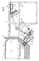
- and tamping device which in the vicinity of the metallurgical vessel 1, i.e. an electric melting furnace 1a, is arranged, in which the liquid steel jet is drained through the perforated brick 2 and through its tap channel 3.
- the closing process is carried out by means of a plug manipulator 8 with the closing plug 5 similar to a plug rod, the closing plug 5 through a closable vessel wall opening 9 (a sliding door 10 can be provided) are pivoted onto a closing axis 11 in the closing position 12 and wherein the closing plug 5 is placed on the closing axis 11 in a sealing manner against the opening 2a becomes.
- the tap hole tamping machine 7 of brought to the outside of the perforated brick 2 on the perforated brick axis 2b.
- the plug manipulator 8 is in a guideway 13, which is arranged next to the vessel 1, can be moved, the closing plug 5 in a sealing layer is brought with the inner perforated brick opening 2a.
- the tap hole drilling and tap hole tamping machine 7 is also in a (further) Guideway 14 next to the vessel 1 movable.
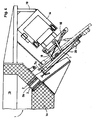
- FIG. 2 an alternative tap hole closing machine 8 is shown, which consists of a Swivel device 15 exists.
- the closing plug 5 is by means of the swivel device 15 through the vessel wall opening 9 from the inside against the perforated brick opening 2a adjustable in the closed position 12.
- the tap hole closing machine 8 is in its parking position 5a.
- the Plug manipulator 8 can be in the horizontal directions 16 and conveniently can be moved at 45 ° extending directions 17.
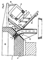
- the tap hole drilling and tap hole tamping machine carries 7 one by means of a lever mechanism 18 on a device frame 19 articulated drilling machine 20.
- the device frame 19 is over the lever mechanism 18 hinges the tap hole tamping machine 7 (FIG. 4).
- the tap hole tamping machine 7 can alternately with the tap hole drilling machine 20 via the im Lever mechanism 18 can be set to the perforated stone axis 2b.
- the lever mechanism 18 can e.g. be formed from a parallelogram linkage (Fig. 6).
- a plate-shaped closure element 7a supports the stuffing compound 6 as long as it is not cured.
- the tap channel 3 closes on the outside on the vessel wall 1c a downwardly extending tapping tube 21.
- the outer arch back 22 is designed as a cover 23, which is by means of a drive can be opened and closed on a joint. When opened, the Tap hole drilling machine 20 are retracted on the perforated stone axis 2b.
- the pivoting device 15 for the closing plug 5 is made of one Angle lever 25 is formed, which is rotatably supported on the device frame 19.
- the a lever arm 25a facing the vessel 1 carries the bracket 26 Locking plug 5 and a swivel drive 27 are connected to the lever arm end 25b.
- the closing plug 5 is at a distance in its movement arc 28 provided to the electrodes 29.
- the sealing plug is for a secure seal (achieving a true-to-shape sealing position) 5 (cf. FIG. 8) via guide bushes 30 and 31 in the sliding directions 32, limited by compression springs 33, resiliently mounted.
- the closing plug 5 is between two side cheeks 34a and 34b over the Guide bush 30 guided attached and at the opposite end 35 by means of Springs 36 are supported against a pocket 37 connected to the bracket 26.
- the bracket 26 is also on the pivot bearing 15a perpendicular to the pivot plane Springs 38 supported. This storage gives a further degree of freedom in the Directions 39.
- the closing plug 5 advantageously consists of a hollow plug 5b, the Cavity can possibly serve to accommodate measuring devices.
Landscapes
- Engineering & Computer Science (AREA)
- Mechanical Engineering (AREA)
- General Engineering & Computer Science (AREA)
- Furnace Charging Or Discharging (AREA)
- Carbon Steel Or Casting Steel Manufacturing (AREA)
- Refinement Of Pig-Iron, Manufacture Of Cast Iron, And Steel Manufacture Other Than In Revolving Furnaces (AREA)
- Vertical, Hearth, Or Arc Furnaces (AREA)
Abstract
Description
wobei kein Problem entsteht. Die Stichlochmasse drückt das Flüssigmetall im Abstichkanal zurück und verschließt diesen.
- Fig. 1
- einen Teilschnitt durch den Abstichbereich eines Elektroschmelzofens mit einem Stopfen-Manipulator und einer Stichloch-Bohr- und Stichloch-Stopfmaschine,
- Fig. 2
- eine alternative Ausführung des Stopfen-Manipulators als Teilschnitt wie Fig. 1,
- Fig. 3
- den gleichen Teilschnitt wie die Fig. 1 und 2 mit dem Stopfen-Manipulator in Parkstellung und der Stichloch-Stopfmaschine in Arbeitsstellung,
- Fig. 4
- den genannten Teilschnitt mit der Stichloch-Bohr- und Stichlochstopfmaschine für die Operation "Bohren",
- Fig. 5
- den Teilschnitt mit der Stichlochstopfmaschine für die Operation "Verschließen",
- Fig. 6
- den Teilschnitt mit einer alternativen Ausführungsform des Abstichkanals und der Stichloch-Bohrmaschine in Wartestellung,
- Fig. 7
- den Teilschnitt für eine alternative Ausführungsform einer Schwenkeinrichtung für den Stopfen-Manipulator,
- Fig. 8
- eine Seitenansicht der Schwenkeinrichtung für den Stopfen-Manipulator und
- Fig. 9
- die zugehörige Draufsicht zu Fig. 8 in Teilschnitten.
- 1
- metallurgisches Gefäß
- 1a
- Elektroschmelzofen
- 1b
- Gefäßinneres
- 1c
- Gefäßwand
- 2
- Lochstein
- 2a
- Lochstein-Öffnung
- 2b
- Lochsteinachse
- 3
- Abstichkanal
- 4
- Schmelzenspiegel
- 5
- Schließstopfen
- 5a
- Schließstopfen-Parkstellung
- 6
- Stopfmasse
- 7
- Stichloch-Bohr- und Stichloch-Stopfmaschine
- 7a
- Verschlusselement
- 8
- Stopfen-Manipulator
- 9
- Gefäßwandöffnung
- 10
- Schiebetür
- 11
- Schließachse
- 12
- Schließposition
- 13
- Führungsbahn
- 14
- (weitere) Führungsbahn
- 15
- Schwenkeinrichtung
- 15a
- Schwenklager
- 16
- horizontale Richtungen
- 17
- Anstellrichtungen
- 18
- Hebelwerk
- 19
- Vorrichtungsrahmen
- 20
- Bohrmaschine
- 21
- gebogenes Abstichrohr
- 22
- Bogenrücken
- 23
- Deckel
- 24
- Antrieb
- 25
- Winkelhebel
- 25a
- Hebelarm
- 25b
- Hebelarmende
- 26
- Bügel
- 27
- Schwenkantrieb
- 28
- Bewegungsbogen
- 29
- Elektroden
- 30
- Führungsbuchse
- 31
- Führungsbuchse
- 32
- Schieberichtungen
- 33
- Druckfeder
- 34a
- Seitenwange
- 34b
- Seitenwange
- 35
- Ende
- 36
- Feder
- 37
- Tasche
- 38
- Feder
- 39
- Richtungen
Claims (15)
- Verfahren zum Stichlochstopfen und / oder Stichlochbohren an einem metallurgischen Gefäß, insbesondere an einem stationären Elektroschmelzofen, bei dem der Flüssigstahl-Strahl durch einen Lochstein des Abstichkanals abgelassen wird,
dadurch gekennzeichnet, dass der Lochstein des Abstichkanals bei gesenktem Schmelzenspiegel vom Gefäßinneren her mit einem Schließstopfen verschlossen wird und dass danach Stopfmasse in den Abstichkanal von außen gedrückt und der Abstichkanal wieder verschlossen wird. - Verfahren nach Anspruch 1,
dadurch gekennzeichnet, dass der Schließstopfen nach einer relativ kurzen Zeit nach dem Eindrücken der Stopfmasse in den Abstichkanal wieder aus dem Inneren des Gefäßes herausbewegt wird. - Verfahren nach einem der Ansprüche 1 oder 2,
dadurch gekennzeichnet, dass die Stopfmaschine mit einem anliegenden Verschlusselement zumindest 30 min vor dem verschlossenen Abstichkanal gehalten wird. - Stichloch-Schließ- und / oder Stichloch-Bohr- und Stopfvorrichtung für ein metallurgisches Gefäß, insbesondere für einen stationären Elektroschmelzofen, bei dem der Flüssigstahl-Strahl durch einen Lochstein und dessen Abstichkanal ablassbar ist,
dadurch gekennzeichnet, dass ein Stopfen-Manipulator (8) mit einem Schließstopfen (5) durch eine verschließbare Gefäßwandöffnung (9) hindurch auf eine Schließachse (11) in Schließposition (12) schwenkbar ist, wobei der Schließstopfen (5) auf der Schließachse (11) an die Öffnung (2a) des Lochsteins (2) dichtend anstellbar ist und dass eine Stichloch-Bohr- und Stichlochstopfmaschine (7) von außen an den Lochstein (2) auf die Lochsteinachse (2b) heranbewegbar ist. - Vorrichtung nach Anspruch 4,
dadurch gekennzeichnet, dass der Stopfen-Manipulator (8) in einer Führungsbahn (13), die außerhalb des Gefäßes (1) angeordnet ist, verfahrbar und mit dem Schließstopfen (5) gegen die gefäßinnere Lochstein-Öffnung (2a) anstellbar ist. - Vorrichtung nach Anspruch 4,
dadurch gekennzeichnet, dass die Stichloch-Bohr- und Stichloch-Stopfmaschine (7) ebenfalls in einer weiteren Führungsbahn (14) außerhalb des Gefäßes (1) verfahrbar ist. - Vorrichtung nach Anspruch 4,
dadurch gekennzeichnet, dass der Schließstopfen (5) mittels einer Schwenkeinrichtung (15) durch die Gefäßwandöffnung (9) hindurch von innen gegen die Lochstein-Öffnung (2a) dichtend anstellbar ist. - Vorrichtung nach Anspruch 7,
dadurch gekennzeichnet, dass die Stichloch-Bohr- und Stichloch-Stopfmaschine (7) eine mittels eines Hebelwerks (18) am Vorrichtungsrahmen (19) angelenkte Bohrmaschine (20) trägt. - Vorrichtung nach einem der Ansprüche 4 bis 8,
dadurch gekennzeichnet, dass zusätzlich zur Stichloch- Bohrmaschine (20) am Vorrichtungsrahmen (19) an einem Hebelwerk (18) die Stichloch-Stopfmaschine (7) angelenkt und wechselweise mit der Stichloch-Bohrmaschine (20) auf die Lochsteinachse (2b) einstellbar ist. - Vorrichtung nach einem der Ansprüche 4 bis 9,
dadurch gekennzeichnet, dass an den Abstichkanal (3) außen an der Gefäßwand (1c) ein nach unten gebogen verlaufendes Abstichrohr (21) anschließt, dessen äußerer Bogenrükken (22) als Deckel (23) ausgebildet und mittels eines Antriebs (24) auf - und zuschwenkbar ist. - Vorrichtung nach Anspruch 6,
dadurch gekennzeichnet, dass die Schwenkeinrichtung (15) für den Schließstopfen (5) aus einem Winkelhebel (25) besteht, der außerhalb des Gefäßes (1) drehgelagert ist, an dessen einem, dem Gefäß (1) zugewandten Hebelarm (25a) über einen Bügel (26) der Schließstopfen (5) befestigt und an dem anderen Hebelarm (25b) ein Schwenkantrieb (27) angeschlossen ist. - Vorrichtung nach einem der Ansprüche 4 bis 11,
dadurch gekennzeichnet, dass der Schließstopfen (5) im Bügel (26) etwa tangential zur Schwenkrichtung federnd gelagert ist. - Vorrichtung nach Anspruch 12,
dadurch gekennzeichnet, dass der Schließstopfen (5) zwischen zwei Seitenwangen (34a, 34b befestigt ist und die Seitenwangen (34a, 34b) in dem Bügel (26) geführt und am gegenüberliegenden Ende (35) mittels Federn (36) gegen jeweils eine mit dem Bügel (26) verbundene Tasche (37) abgestützt ist. - Vorrichtung nach einem der Ansprüche 12 oder 13,
dadurch gekennzeichnet, dass der Bügel (26) am Schwenklager (15a) senkrecht zur Schwenkebene federnd gelagert ist. - Vorrichtung nach einem der Ansprüche 4 bis 14,
dadurch gekennzeichnet, dass der Schließstopfen (5) aus einem Hohlstopfen (5b) besteht.
Applications Claiming Priority (2)
| Application Number | Priority Date | Filing Date | Title |
|---|---|---|---|
| DE2001111275 DE10111275A1 (de) | 2001-03-09 | 2001-03-09 | Verfahren und Vorrichtung zum Stichlochstopfen und/oder Stichlochbohren an einem metallurgischen Gefäß, insbesondere an einem Elektroschmelzofen |
| DE10111275 | 2001-03-09 |
Publications (2)
| Publication Number | Publication Date |
|---|---|
| EP1239249A2 true EP1239249A2 (de) | 2002-09-11 |
| EP1239249A3 EP1239249A3 (de) | 2002-12-18 |
Family
ID=7676801
Family Applications (1)
| Application Number | Title | Priority Date | Filing Date |
|---|---|---|---|
| EP02003949A Withdrawn EP1239249A3 (de) | 2001-03-09 | 2002-02-22 | Verfahren und Vorrichtung zum Stichlochstopfen und/oder Stichlochbohren an einem metallurgischen Gefäss, insbesondere an einem Elektroschmelzofen |
Country Status (2)
| Country | Link |
|---|---|
| EP (1) | EP1239249A3 (de) |
| DE (1) | DE10111275A1 (de) |
Cited By (9)
| Publication number | Priority date | Publication date | Assignee | Title |
|---|---|---|---|---|
| WO2004036131A1 (en) * | 2002-10-15 | 2004-04-29 | Sms Demag Ag | Electric furnace for steel making |
| CN103307885A (zh) * | 2013-07-01 | 2013-09-18 | 哈尔滨博实自动化股份有限公司 | 机器人自动开堵炉眼装置 |
| CN105043109A (zh) * | 2015-08-18 | 2015-11-11 | 江西瑞林装备有限公司 | 用于冶金炉的捅打装置 |
| CN106940140B (zh) * | 2017-02-28 | 2018-09-04 | 西安交通大学 | 一种带有流量温度监测及控制功能的二级液态熔渣缓存系统 |
| CN111023835A (zh) * | 2020-01-02 | 2020-04-17 | 江苏新春兴再生资源有限责任公司 | 一种铅熔炼炉无氧放铅自动控制装置 |
| CN111912238A (zh) * | 2019-05-08 | 2020-11-10 | 晟通科技集团有限公司 | 铝熔体自动控流装置 |
| WO2021109328A1 (zh) * | 2019-12-04 | 2021-06-10 | 西安交通大学 | 一种液态熔渣余热回收系统 |
| CN113233501A (zh) * | 2021-06-29 | 2021-08-10 | 攀钢集团攀枝花钛材有限公司 | 熔盐氯化炉底部排盐装置 |
| CN119915101A (zh) * | 2025-04-03 | 2025-05-02 | 交城义望铁合金有限责任公司 | 一种铁合金精炼电炉自动化开炉系统 |
Family Cites Families (5)
| Publication number | Priority date | Publication date | Assignee | Title |
|---|---|---|---|---|
| JPS5877517A (ja) * | 1981-10-30 | 1983-05-10 | Nippon Kokan Kk <Nkk> | 転炉スラグ分離方法 |
| DE3437810A1 (de) * | 1984-10-16 | 1986-04-24 | Kortec AG, Zug | Verschlusseinrichtung fuer eine abstichoeffnung im boden eines metallurgischen gefaesses |
| LU88203A1 (fr) * | 1992-12-16 | 1994-09-09 | Wurth Paul Sa | Machine combinée pour le perçage et le bouchage d'un trou de coulée d'un four à cuve |
| DE19826085C2 (de) * | 1998-06-12 | 2000-08-03 | Sms Demag Ag | Verfahren und Vorrichtung zum Abdichten einer Abstichöffnung in metallurgischen Gefäßen |
| DE10111273A1 (de) * | 2001-03-09 | 2002-09-12 | Sms Demag Ag | Verfahren und Einrichtung zum Auswechseln einer Schieberbaugruppe an einem metallurgischen Gefäß, insbesondere an einem Elektroschmelzofen |
-
2001
- 2001-03-09 DE DE2001111275 patent/DE10111275A1/de not_active Withdrawn
-
2002
- 2002-02-22 EP EP02003949A patent/EP1239249A3/de not_active Withdrawn
Cited By (12)
| Publication number | Priority date | Publication date | Assignee | Title |
|---|---|---|---|---|
| WO2004036131A1 (en) * | 2002-10-15 | 2004-04-29 | Sms Demag Ag | Electric furnace for steel making |
| CN103307885A (zh) * | 2013-07-01 | 2013-09-18 | 哈尔滨博实自动化股份有限公司 | 机器人自动开堵炉眼装置 |
| CN103307885B (zh) * | 2013-07-01 | 2015-06-10 | 哈尔滨博实自动化股份有限公司 | 机器人自动开堵炉眼装置 |
| CN105043109A (zh) * | 2015-08-18 | 2015-11-11 | 江西瑞林装备有限公司 | 用于冶金炉的捅打装置 |
| CN105043109B (zh) * | 2015-08-18 | 2017-04-19 | 江西瑞林装备有限公司 | 用于冶金炉的捅打装置 |
| CN106940140B (zh) * | 2017-02-28 | 2018-09-04 | 西安交通大学 | 一种带有流量温度监测及控制功能的二级液态熔渣缓存系统 |
| CN111912238A (zh) * | 2019-05-08 | 2020-11-10 | 晟通科技集团有限公司 | 铝熔体自动控流装置 |
| WO2021109328A1 (zh) * | 2019-12-04 | 2021-06-10 | 西安交通大学 | 一种液态熔渣余热回收系统 |
| CN111023835A (zh) * | 2020-01-02 | 2020-04-17 | 江苏新春兴再生资源有限责任公司 | 一种铅熔炼炉无氧放铅自动控制装置 |
| CN113233501A (zh) * | 2021-06-29 | 2021-08-10 | 攀钢集团攀枝花钛材有限公司 | 熔盐氯化炉底部排盐装置 |
| CN113233501B (zh) * | 2021-06-29 | 2022-06-03 | 攀钢集团攀枝花钛材有限公司 | 熔盐氯化炉底部排盐装置 |
| CN119915101A (zh) * | 2025-04-03 | 2025-05-02 | 交城义望铁合金有限责任公司 | 一种铁合金精炼电炉自动化开炉系统 |
Also Published As
| Publication number | Publication date |
|---|---|
| EP1239249A3 (de) | 2002-12-18 |
| DE10111275A1 (de) | 2002-09-12 |
Similar Documents
| Publication | Publication Date | Title |
|---|---|---|
| EP2056983B1 (de) | Verfahren zur wartung eines am ausguss eines behälters für metallschmelze montierten schiebeverschlusses | |
| DE10111275A1 (de) | Verfahren und Vorrichtung zum Stichlochstopfen und/oder Stichlochbohren an einem metallurgischen Gefäß, insbesondere an einem Elektroschmelzofen | |
| EP0819488B1 (de) | Schiebeverschluss für einen Metallschmelze enthaltenden Behälter | |
| WO2010094571A1 (de) | Stichlochbohrmaschine für metallurgische behälter, insbesondere öfen mit schmelzflüssigem inhalt | |
| DE3530471A1 (de) | Induktionsofen mit einem ofenunterteil und einem deckel | |
| EP0182974B1 (de) | Verfahren und Vorrichtung zum Öffnen und Schliessen eines Stichloches an Öfen | |
| DE3833504A1 (de) | Gasspueleinrichtung | |
| EP0343413A2 (de) | Vorrichtung zum Reinigen solcher Teile von Kunststoffverarbeitungsmaschinen, an denen Kunststoffreste anhaften | |
| DD276888A5 (de) | Sublanzenvorrichtung zur durchfuehrung von messungen und/oder entnahme von proben in einem hochofen | |
| DE1928400B2 (de) | Verschlußvorrichtung für die Boden-Ausgussöffnung einer Giesspfanne | |
| DE2508445B2 (de) | Vorrichtung zur herstellung von flachglas | |
| DE2504918B2 (de) | Tiegel zum schmelzen und vornehmlich zum warmhalten und giessen von metallen | |
| DE2455029A1 (de) | Schmelzenpfanne und verfahren fuer die herstellung von vakuumstahl | |
| EP0446237A1 (de) | Ofenanlage zum einschmelzen von schrott. | |
| DE2715697C3 (de) | Plasmalichtbogenschmelzofen | |
| CN117606247B (zh) | 一种炉口炮泥封堵系统及熔融铁合金冶炼系统 | |
| DE2907573A1 (de) | Einrichtung fuer das nitrieren von metallischen werkstoffen und ferrolegierungen unter druck | |
| DE3729437A1 (de) | Vorrichtung zum ein- und/oder ausfuehren von brennerlanzen, probenehmern und dergl. durch die oeffnung eines behaelters | |
| DE2943319C2 (de) | Einrichtung zur Verhinderung des Austretens von Füllgasen bei mit Stampfkuchen beschickten waagerechten Kammern von Verkokungsöfen | |
| EP4215715B1 (de) | Kastenbohrer und verfahren zum erstellen einer bohrung | |
| EP1743948B1 (de) | Schmelzofen und Verfahren zu dessen Betrieb | |
| EP1150085A1 (de) | Drehtrommelofen zum Schmelzen von Metallen | |
| DE10034049A1 (de) | Abstichsystem für nicht kippbaren E-Ofen | |
| DE2623545B2 (de) | Abgashaube für eine Gießpfanne und Gießeinrichtung | |
| DE3337657A1 (de) | Einrichtung zum einschmelzen von schrott und abfaellen aus nicht-eisenmetallen |
Legal Events
| Date | Code | Title | Description |
|---|---|---|---|
| PUAI | Public reference made under article 153(3) epc to a published international application that has entered the european phase |
Free format text: ORIGINAL CODE: 0009012 |
|
| 17P | Request for examination filed |
Effective date: 20020222 |
|
| AK | Designated contracting states |
Kind code of ref document: A2 Designated state(s): AT BE CH CY DE DK ES FI FR GB GR IE IT LI LU MC NL PT SE TR |
|
| AX | Request for extension of the european patent |
Free format text: AL;LT;LV;MK;RO;SI |
|
| PUAL | Search report despatched |
Free format text: ORIGINAL CODE: 0009013 |
|
| AK | Designated contracting states |
Kind code of ref document: A3 Designated state(s): AT BE CH CY DE DK ES FI FR GB GR IE IT LI LU MC NL PT SE TR |
|
| AX | Request for extension of the european patent |
Free format text: AL;LT;LV;MK;RO;SI |
|
| RIC1 | Information provided on ipc code assigned before grant |
Free format text: 7F 27D 3/15 A, 7C 21C 5/46 B |
|
| AKX | Designation fees paid |
Designated state(s): AT BE CH CY DE DK ES FI FR GB GR IE IT LI LU MC NL PT SE TR |
|
| STAA | Information on the status of an ep patent application or granted ep patent |
Free format text: STATUS: THE APPLICATION HAS BEEN WITHDRAWN |
|
| 18W | Application withdrawn |
Effective date: 20050305 |