EP1236829A2 - Prallströmtrockner - Google Patents
Prallströmtrockner Download PDFInfo
- Publication number
- EP1236829A2 EP1236829A2 EP01125932A EP01125932A EP1236829A2 EP 1236829 A2 EP1236829 A2 EP 1236829A2 EP 01125932 A EP01125932 A EP 01125932A EP 01125932 A EP01125932 A EP 01125932A EP 1236829 A2 EP1236829 A2 EP 1236829A2
- Authority
- EP
- European Patent Office
- Prior art keywords
- dryer according
- impingement
- impingement flow
- fibrous web
- cooling
- Prior art date
- Legal status (The legal status is an assumption and is not a legal conclusion. Google has not performed a legal analysis and makes no representation as to the accuracy of the status listed.)
- Granted
Links
Images
Classifications
-
- D—TEXTILES; PAPER
- D21—PAPER-MAKING; PRODUCTION OF CELLULOSE
- D21F—PAPER-MAKING MACHINES; METHODS OF PRODUCING PAPER THEREON
- D21F5/00—Dryer section of machines for making continuous webs of paper
- D21F5/18—Drying webs by hot air
-
- D—TEXTILES; PAPER
- D21—PAPER-MAKING; PRODUCTION OF CELLULOSE
- D21F—PAPER-MAKING MACHINES; METHODS OF PRODUCING PAPER THEREON
- D21F5/00—Dryer section of machines for making continuous webs of paper
- D21F5/02—Drying on cylinders
- D21F5/04—Drying on cylinders on two or more drying cylinders
- D21F5/042—Drying on cylinders on two or more drying cylinders in combination with suction or blowing devices
- D21F5/044—Drying on cylinders on two or more drying cylinders in combination with suction or blowing devices using air hoods over the cylinders
Definitions
- the invention relates to an impingement dryer for drying a paper, cardboard, Tissue or another fibrous web in which the fibrous web is on one side a hot air and / or hot steam impingement flow is applied and with the opposite side on an air-permeable, endless all-round support band supported.
- Impingement flow dryers of this type are known, for example, from DE 19841768 A1, being part of the dryer section of a paper machine.
- the temperature of the Hot air or hot steam can reach values between 300 ° and 500 ° C.
- the temperature resistance of the candidate Support bands especially because of the plastic content between 140 and 240 ° C.
- the width of the impingement dryer is usually the same as the web width limited, which, however, involves difficulties or considerable effort changing width of the fibrous web brings with it.
- the object of the invention is therefore to create a simple thermal Protection of the support band without significantly affecting the drying of the Fibrous web.
- the object was achieved in that at least the one with the Hot air and / or hot steam impingement flow directly applied edge zone of the support band is cooled.
- the cooling of the endangered area of the support band The support belt provides adequate protection for each cycle without drying the fibrous web to affect. For this it is usually sufficient if the fiber web is not covered edge of the support band is cooled.
- the edge of the support band is in a range between 50 and 1000 mm cooled.
- the cooling of the Support band different in cooling zones defined transversely to the web running direction strongly done. This enables the necessary cooling intensity to be adjusted for example, the local temperature of the support band.
- the cooling capacity assigned to the cooling zones can be controlled separately.
- the support belt is cooled by at least one cooling device in Form of liquid and / or compressed air nozzles. This should be the liquid nozzles be supplied with a liquid whose boiling temperature is below the maximum permissible
- the temperature of the support band is, preferably water or alcohols, for example Polyethylene glycol.
- This evaporative cooling prevents sufficient Hydration that the temperature of the support band above the boiling point the liquid rises.
- rewetting of the fibrous web should prevent that from the support belt bounced liquid and / or liquid mist emanating therefrom from guide elements and / or collecting devices and / or suction devices become.
- the pressure and / or the throughput of the Liquid and / or compressed air nozzles can preferably be controlled individually or in zones his.
- This enables the cooling capacity depending on the heating capacity adjust the impingement dryer, preferably to control and / or depending on the temperature of the support belt, in particular the temperature of the concerned To regulate the cooling zone and / or depending on an upstream tear detection to control the fibrous web.
- Temperature sensors are used for this Measurement of the temperature of the support belt in the web running direction before and under certain circumstances but also helpful after the cooling device, especially when compared the edge of the support band should be arranged. For comparison purposes is also the measurement of the temperature of the support band in the middle range of Advantage.
- the support band should be designed as a sieve. It is also for Ensuring stable running of the support belt and thus also the fibrous web and in terms of the distance to the impingement dryer advantageous if that Support tape during the application of the hot air and / or the fibrous web Hot steam impingement flow is guided over a rotating support roller.
- a constructive one A simple solution arises if the hot air and / or hot steam impingement flow from a drying hood arranged in a peripheral region of the support roller is produced.
- the cooling of the support belt according to the invention is also in the case of hot air floating dryers used.
- the cooling of the support belt can be outside the area leading the fibrous web if necessary, take place in several places along the run of the support belt.
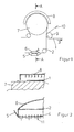
- the impingement dryer is part of a paper machine for drying the fibrous web 1 and is essentially a rotating support roller 7 and a drying hood 8 formed.
- the drying hood 8 is a few centimeters apart arranged to support roller 7 and extends over a substantial part of the Circumference of the support roller 7.
- the support roller 7 is supported by an endlessly rotating support belt 2 in the form of a dryer fabric and the outer fibrous web 1 wrapped.
- From the in Drying hood 8 arranged in the wrapping area is applied to the Fibrous web 1 with hot air, which leads to drying of the fibrous web 1.
- the support band 2 is inevitably wider than the fibrous web 1. This leads in particular when the width of the fibrous web 1 changes, that an edge zone the support band 2 directly, d. H. without the fibrous web 1 in between Hot air is exposed, which is too thermal due to the plastic content in the support band 2 Damage can result.
- the support belt 2 guides the fibrous web 1 from the support roller 7 to one, wrapped and sucked by an air-permeable sieve 10 Guide roller 9.
- the guide roller 9 supports the transfer of the vacuum Fibrous web 1 to the sieve 10.
- the support band 2 After the delivery of the fibrous web 1, the support band 2 over its entire Width cooled by a cooling device in the form of water nozzles 4.
- a cooling device in the form of water nozzles 4.
- the edge zone of the support band 2 which is directly exposed to the hot air is particularly strongly cooled.
- the water nozzles 4 are in a hood and open towards the support band 2 are in several, lying one behind the other in the direction of web 3 Arranged rows.
- the cooling of the support belt 2 takes place in a direction delimited transversely to the web running direction 3 Cooling zones vary in strength.
- the cooling capacity assigned to the cooling zones To be able to control separately, the water nozzles 4 of the cooling zone in question are included a common pressure line 11 controllable via a valve.
- the cooling capacity is also in the case of a tear of the fibrous web 1 in an upstream Unit of the paper machine reinforced and that over the entire width. at the control of the cooling capacity is also the heating capacity of the drying hood 8 as well as the temperature of the support belt 2 detected by sensors.
Landscapes
- Paper (AREA)
Abstract
Description
Claims (18)
- Prallströmtrockner zur Trocknung einer Papier-, Karton-, Tissue- oder einer anderen Faserstoffbahn (1), bei dem die Faserstoffbahn (1) einseitig mit einer Heißluft-und/oder Heißdampfprallströmung beaufschlagt wird und sich mit der gegenüberliegenden Seite auf einem luftdurchlässigen, endlos umlaufenden Stützband (2) abstützt, dadurch gekennzeichnet, dass
zumindest die mit der Heißluft-und/oder Heißdampfprallströmung direkt beaufschlagte Randzone des Stützbandes (2) gekühlt wird. - Prallströmtrockner nach Anspruch 1, dadurch gekennzeichnet, dass
die Kühlung des Stützbandes (2) nach der Abgabe der Faserstoffbahn (1) von diesem an eine folgende Einheit erfolgt. - Prallströmtrockner nach Anspruch 1 oder 2, dadurch gekennzeichnet, dass
zumindest der nicht von der Faserstoffbahn (1) abgedeckte Rand des Stützbandes (2) gekühlt wird. - Prallströmtrockner nach einem der vorhergehenden Ansprüche, dadurch gekennzeichnet, dass
der Rand des Stützbandes (2) in einem Breitenbereich zwischen 50 und 1000 mm gekühlt wird. - Prallströmtrockner nach einem der vorhergehenden Ansprüche, dadurch gekennzeichnet, dass
das Stützband (2) über die gesamte Breite gekühlt wird. - Prallströmtrockner nach einem der vorhergehenden Ansprüche, dadurch gekennzeichnet, dass
die Kühlung des Stützbandes (2) in quer zur Bahnlaufrichtung (3) abgegrenzten Kühlzonen unterschiedlich stark erfolgt. - Prallströmtrockner nach Anspruch 6, dadurch gekennzeichnet, dass
die den Kühlzonen zugeordnete Kühlleistung separat steuerbar ist. - Prallströmtrockner nach einem der vorhergehenden Ansprüche, dadurch gekennzeichnet, dass
die Kühlung des Stützbandes (2) durch wenigstens eine Kühleinrichtung in Form von Flüssigkeits- und/oder Druckluftdüsen (4) erfolgt. - Prallströmtrockner nach Anspruch 8, dadurch gekennzeichnet, dass
den Flüssigkeitsdüsen (4) eine Flüssigkeit zugeführt wird, deren Siedetemperatur unter der maximal zulässigen Temperatur des Stützbandes (2) liegt, vorzugsweise Wasser oder Alkohole, beispielsweise Polyethylenglykol. - Prallströmtrockner nach Anspruch 8 oder 9, dadurch gekennzeichnet, dass
die vom Stützband (2) abgeprallte Flüssigkeit und/oder davon ausgehender Flüssigkeitsnebel von Leitelementen und/oder Auffangvorrichtungen (5) und/oder Absaugeinrichtungen (6) abgeführt wird. - Prallströmtrockner nach einem der Ansprüche 8 bis 10, dadurch gekennzeichnet, dass
der Druck und/oder der Durchsatz der Flüssigkeits- und/oder Druckluftdüsen vorzugsweise einzeln oder zonenweise separat steuerbar ist. - Prallströmtrockner nach einem der vorhergehenden Ansprüche, dadurch gekennzeichnet, dass
die Kühlleistung in Abhängigkeit von der Heizleistung des Prallströmtrockners eingestellt, vorzugsweise gesteuert wird. - Prallströmtrockner nach einem der vorhergehenden Ansprüche, dadurch gekennzeichnet, dass
die Kühlleistung in Abhängigkeit von der Temperatur des Stützbandes (2), insbesondere der Temperatur der betreffenden Kühlzone geregelt wird. - Prallströmtrockner nach einem der vorhergehenden Ansprüche, dadurch gekennzeichnet, dass
die Kühlleistung in Abhängigkeit von einer vorgelagerten Abrißerkennung der Faserstoffbahn (1) gesteuert wird. - Prallströmtrockner nach einem der vorhergehenden Ansprüche, dadurch gekennzeichnet, dass
das Stützband (2) als Sieb ausgeführt ist. - Prallströmtrockner nach einem der vorhergehenden Ansprüche, dadurch gekennzeichnet, dass
das Stützband (2) während der Beaufschlagung der Faserstoffbahn (1) mit der Heißluft-und/oder Heißdampfprallströmung über eine rotierende Stützwalze (7) geführt wird. - Prallströmtrockner nach Anspruch 16, dadurch gekennzeichnet, dass
die Heißluft-und/oder Heißdampfprallströmung von einer, in einem Umfangsbereich der Stützwalze (7) angeordneten Trockenhaube (8) ausgeht. - Prallströmtrockner nach einem der vorhergehenden Ansprüche, dadurch gekennzeichnet, dass
die Kühlung des Stützbandes (2) außerhalb des die Faserstoffbahn (1) führenden Bereiches an mehreren Stellen entlang des Laufs des Stützbandes (2) erfolgt.
Applications Claiming Priority (2)
| Application Number | Priority Date | Filing Date | Title |
|---|---|---|---|
| DE10109525 | 2001-02-28 | ||
| DE10109525A DE10109525A1 (de) | 2001-02-28 | 2001-02-28 | Prallströmtrockner |
Publications (3)
| Publication Number | Publication Date |
|---|---|
| EP1236829A2 true EP1236829A2 (de) | 2002-09-04 |
| EP1236829A3 EP1236829A3 (de) | 2004-01-14 |
| EP1236829B1 EP1236829B1 (de) | 2006-09-27 |
Family
ID=7675730
Family Applications (1)
| Application Number | Title | Priority Date | Filing Date |
|---|---|---|---|
| EP01125932A Expired - Lifetime EP1236829B1 (de) | 2001-02-28 | 2001-10-31 | Prallströmtrockner |
Country Status (3)
| Country | Link |
|---|---|
| US (1) | US20020116838A1 (de) |
| EP (1) | EP1236829B1 (de) |
| DE (2) | DE10109525A1 (de) |
Families Citing this family (1)
| Publication number | Priority date | Publication date | Assignee | Title |
|---|---|---|---|---|
| DE102016125172A1 (de) * | 2016-12-21 | 2018-06-21 | Voith Patent Gmbh | Verfahren zum Betrieb eines Heizgruppenteilsystems und Heizgruppenteilsystem |
Family Cites Families (6)
| Publication number | Priority date | Publication date | Assignee | Title |
|---|---|---|---|---|
| US4361466A (en) * | 1977-10-27 | 1982-11-30 | Beloit Corporation | Air impingement web drying method and apparatus |
| US5588223A (en) * | 1994-06-14 | 1996-12-31 | Asea Brown Boveri Inc. | Restrained paper dryer |
| FI102624B (fi) * | 1994-06-23 | 1999-01-15 | Valmet Corp | Menetelmä ja laite paperiradan tai vastaavan kuivatuksessa tai jäähdyt yksessä |
| EP1125020B1 (de) * | 1998-08-04 | 2004-11-17 | Metso Paper, Inc. | Verfahren und vorrichtung zur behandlung von papier oder pappebahnen |
| DE19841768A1 (de) * | 1998-09-11 | 2000-03-16 | Voith Sulzer Papiertech Patent | Trockenpartie |
| FI106269B (fi) * | 1999-05-10 | 2000-12-29 | Valmet Corp | Päällepuhallussovitelma ja -menetelmä käsiteltävän paperi- tai kartonkirainan käyristymistaipumuksen kompensoimiseksi sekä paperi- tai kartonkikone |
-
2001
- 2001-02-28 DE DE10109525A patent/DE10109525A1/de not_active Withdrawn
- 2001-10-31 EP EP01125932A patent/EP1236829B1/de not_active Expired - Lifetime
- 2001-10-31 DE DE50111090T patent/DE50111090D1/de not_active Expired - Lifetime
-
2002
- 2002-01-31 US US10/059,333 patent/US20020116838A1/en not_active Abandoned
Also Published As
| Publication number | Publication date |
|---|---|
| US20020116838A1 (en) | 2002-08-29 |
| DE50111090D1 (de) | 2006-11-09 |
| EP1236829B1 (de) | 2006-09-27 |
| DE10109525A1 (de) | 2002-09-05 |
| EP1236829A3 (de) | 2004-01-14 |
Similar Documents
| Publication | Publication Date | Title |
|---|---|---|
| EP0787854B1 (de) | Vorrichtung zum Führen einer Faserstoffbahn in einer einreihigen Trockenpartie | |
| DE3807857C2 (de) | ||
| EP0988417B1 (de) | Trockenpartie | |
| EP0989232B1 (de) | Trockenpartie | |
| DE60029002T2 (de) | Vorrichtung zur Trocknung einer feuchten Papierbahn | |
| AT413709B (de) | Vorrichtung zum kontinuierlichen trocknen einer faserstoffbahn | |
| DE4013485C2 (de) | Verfahren und Vorrichtung zur Effektivierung der Bahnendaufführung in einer Papiermaschinentrockenpartie | |
| DE00989077T1 (de) | Vorrichtung zur bahnüberführung einer schnelllaufenden faserstoffbahn von einem ersten an einen zweiten ort | |
| EP0989233B1 (de) | Trockenpartie sowie Konvektionstrockner für eine solche Trockenpartie | |
| AT394063B (de) | Trocknungsvorrichtung | |
| DE60215526T2 (de) | Gerät zum Führen eines Bahnaufführendstückes über einen leeren Raum | |
| EP1236829B1 (de) | Prallströmtrockner | |
| DE3205962A1 (de) | Waermebehandlungskanal | |
| DE4303315A1 (en) | Paper-making roller scraper - acts together with moist air to reduce blade wear | |
| DE9100762U1 (de) | Trockenpartie | |
| EP1586700B1 (de) | Papiermaschine | |
| EP0192207B1 (de) | Furniertrockner für Messerfurniere | |
| DE3922361C2 (de) | ||
| DE29703627U1 (de) | Vorrichtung zum Abdichten eines Dampfblaskastens | |
| DE19944266A1 (de) | Verfahren zum Trocknen einer Materialbahn | |
| DE19723532A1 (de) | Beheizter Trockenzylinder | |
| DE2917057C2 (de) | Kontinuierlich arbeitende Dekatiermaschine | |
| DE4012421A1 (de) | Trockenpartie einer papiermaschine | |
| DE102004017812A1 (de) | Druckhaube | |
| EP1046739A2 (de) | Verfahren und Vorrichtung zum Fixieren von Schlauchware |
Legal Events
| Date | Code | Title | Description |
|---|---|---|---|
| PUAI | Public reference made under article 153(3) epc to a published international application that has entered the european phase |
Free format text: ORIGINAL CODE: 0009012 |
|
| AK | Designated contracting states |
Kind code of ref document: A2 Designated state(s): AT BE CH CY DE DK ES FI FR GB GR IE IT LI LU MC NL PT SE TR |
|
| AX | Request for extension of the european patent |
Free format text: AL;LT;LV;MK;RO;SI |
|
| PUAL | Search report despatched |
Free format text: ORIGINAL CODE: 0009013 |
|
| AK | Designated contracting states |
Kind code of ref document: A3 Designated state(s): AT BE CH CY DE DK ES FI FR GB GR IE IT LI LU MC NL PT SE TR |
|
| AX | Request for extension of the european patent |
Extension state: AL LT LV MK RO SI |
|
| 17P | Request for examination filed |
Effective date: 20040714 |
|
| AKX | Designation fees paid |
Designated state(s): DE FI SE |
|
| GRAP | Despatch of communication of intention to grant a patent |
Free format text: ORIGINAL CODE: EPIDOSNIGR1 |
|
| RTI1 | Title (correction) |
Free format text: IMPINGEMENT DRYER |
|
| GRAS | Grant fee paid |
Free format text: ORIGINAL CODE: EPIDOSNIGR3 |
|
| GRAA | (expected) grant |
Free format text: ORIGINAL CODE: 0009210 |
|
| RAP1 | Party data changed (applicant data changed or rights of an application transferred) |
Owner name: VOITH PATENT GMBH |
|
| AK | Designated contracting states |
Kind code of ref document: B1 Designated state(s): DE FI SE |
|
| REF | Corresponds to: |
Ref document number: 50111090 Country of ref document: DE Date of ref document: 20061109 Kind code of ref document: P |
|
| REG | Reference to a national code |
Ref country code: SE Ref legal event code: TRGR |
|
| PLBE | No opposition filed within time limit |
Free format text: ORIGINAL CODE: 0009261 |
|
| STAA | Information on the status of an ep patent application or granted ep patent |
Free format text: STATUS: NO OPPOSITION FILED WITHIN TIME LIMIT |
|
| 26N | No opposition filed |
Effective date: 20070628 |
|
| PGFP | Annual fee paid to national office [announced via postgrant information from national office to epo] |
Ref country code: DE Payment date: 20091026 Year of fee payment: 9 Ref country code: FI Payment date: 20091015 Year of fee payment: 9 Ref country code: SE Payment date: 20091014 Year of fee payment: 9 |
|
| REG | Reference to a national code |
Ref country code: SE Ref legal event code: EUG |
|
| PG25 | Lapsed in a contracting state [announced via postgrant information from national office to epo] |
Ref country code: FI Free format text: LAPSE BECAUSE OF NON-PAYMENT OF DUE FEES Effective date: 20101031 |
|
| REG | Reference to a national code |
Ref country code: DE Ref legal event code: R119 Ref document number: 50111090 Country of ref document: DE Effective date: 20110502 |
|
| PG25 | Lapsed in a contracting state [announced via postgrant information from national office to epo] |
Ref country code: SE Free format text: LAPSE BECAUSE OF NON-PAYMENT OF DUE FEES Effective date: 20101101 |
|
| PG25 | Lapsed in a contracting state [announced via postgrant information from national office to epo] |
Ref country code: DE Free format text: LAPSE BECAUSE OF NON-PAYMENT OF DUE FEES Effective date: 20110502 |