EP1236559A1 - Dispositif et procédé d'extrusion d'un profile à la périphérie de la surface d'un vitrage et un vitrage pourvu d'un cadre profilé - Google Patents
Dispositif et procédé d'extrusion d'un profile à la périphérie de la surface d'un vitrage et un vitrage pourvu d'un cadre profilé Download PDFInfo
- Publication number
- EP1236559A1 EP1236559A1 EP01830147A EP01830147A EP1236559A1 EP 1236559 A1 EP1236559 A1 EP 1236559A1 EP 01830147 A EP01830147 A EP 01830147A EP 01830147 A EP01830147 A EP 01830147A EP 1236559 A1 EP1236559 A1 EP 1236559A1
- Authority
- EP
- European Patent Office
- Prior art keywords
- glazing
- profile
- extrusion
- extruded
- nozzle
- Prior art date
- Legal status (The legal status is an assumption and is not a legal conclusion. Google has not performed a legal analysis and makes no representation as to the accuracy of the status listed.)
- Withdrawn
Links
Images

Classifications
-
- B—PERFORMING OPERATIONS; TRANSPORTING
- B29—WORKING OF PLASTICS; WORKING OF SUBSTANCES IN A PLASTIC STATE IN GENERAL
- B29C—SHAPING OR JOINING OF PLASTICS; SHAPING OF MATERIAL IN A PLASTIC STATE, NOT OTHERWISE PROVIDED FOR; AFTER-TREATMENT OF THE SHAPED PRODUCTS, e.g. REPAIRING
- B29C48/00—Extrusion moulding, i.e. expressing the moulding material through a die or nozzle which imparts the desired form; Apparatus therefor
- B29C48/25—Component parts, details or accessories; Auxiliary operations
- B29C48/30—Extrusion nozzles or dies
- B29C48/32—Extrusion nozzles or dies with annular openings, e.g. for forming tubular articles
- B29C48/33—Extrusion nozzles or dies with annular openings, e.g. for forming tubular articles with parts rotatable relative to each other
-
- B—PERFORMING OPERATIONS; TRANSPORTING
- B29—WORKING OF PLASTICS; WORKING OF SUBSTANCES IN A PLASTIC STATE IN GENERAL
- B29C—SHAPING OR JOINING OF PLASTICS; SHAPING OF MATERIAL IN A PLASTIC STATE, NOT OTHERWISE PROVIDED FOR; AFTER-TREATMENT OF THE SHAPED PRODUCTS, e.g. REPAIRING
- B29C48/00—Extrusion moulding, i.e. expressing the moulding material through a die or nozzle which imparts the desired form; Apparatus therefor
- B29C48/03—Extrusion moulding, i.e. expressing the moulding material through a die or nozzle which imparts the desired form; Apparatus therefor characterised by the shape of the extruded material at extrusion
- B29C48/12—Articles with an irregular circumference when viewed in cross-section, e.g. window profiles
-
- B—PERFORMING OPERATIONS; TRANSPORTING
- B29—WORKING OF PLASTICS; WORKING OF SUBSTANCES IN A PLASTIC STATE IN GENERAL
- B29C—SHAPING OR JOINING OF PLASTICS; SHAPING OF MATERIAL IN A PLASTIC STATE, NOT OTHERWISE PROVIDED FOR; AFTER-TREATMENT OF THE SHAPED PRODUCTS, e.g. REPAIRING
- B29C48/00—Extrusion moulding, i.e. expressing the moulding material through a die or nozzle which imparts the desired form; Apparatus therefor
- B29C48/15—Extrusion moulding, i.e. expressing the moulding material through a die or nozzle which imparts the desired form; Apparatus therefor incorporating preformed parts or layers, e.g. extrusion moulding around inserts
- B29C48/154—Coating solid articles, i.e. non-hollow articles
- B29C48/155—Partial coating thereof
-
- B—PERFORMING OPERATIONS; TRANSPORTING
- B29—WORKING OF PLASTICS; WORKING OF SUBSTANCES IN A PLASTIC STATE IN GENERAL
- B29C—SHAPING OR JOINING OF PLASTICS; SHAPING OF MATERIAL IN A PLASTIC STATE, NOT OTHERWISE PROVIDED FOR; AFTER-TREATMENT OF THE SHAPED PRODUCTS, e.g. REPAIRING
- B29C48/00—Extrusion moulding, i.e. expressing the moulding material through a die or nozzle which imparts the desired form; Apparatus therefor
- B29C48/03—Extrusion moulding, i.e. expressing the moulding material through a die or nozzle which imparts the desired form; Apparatus therefor characterised by the shape of the extruded material at extrusion
- B29C48/06—Rod-shaped
-
- B—PERFORMING OPERATIONS; TRANSPORTING
- B29—WORKING OF PLASTICS; WORKING OF SUBSTANCES IN A PLASTIC STATE IN GENERAL
- B29C—SHAPING OR JOINING OF PLASTICS; SHAPING OF MATERIAL IN A PLASTIC STATE, NOT OTHERWISE PROVIDED FOR; AFTER-TREATMENT OF THE SHAPED PRODUCTS, e.g. REPAIRING
- B29C48/00—Extrusion moulding, i.e. expressing the moulding material through a die or nozzle which imparts the desired form; Apparatus therefor
- B29C48/03—Extrusion moulding, i.e. expressing the moulding material through a die or nozzle which imparts the desired form; Apparatus therefor characterised by the shape of the extruded material at extrusion
- B29C48/07—Flat, e.g. panels
-
- Y—GENERAL TAGGING OF NEW TECHNOLOGICAL DEVELOPMENTS; GENERAL TAGGING OF CROSS-SECTIONAL TECHNOLOGIES SPANNING OVER SEVERAL SECTIONS OF THE IPC; TECHNICAL SUBJECTS COVERED BY FORMER USPC CROSS-REFERENCE ART COLLECTIONS [XRACs] AND DIGESTS
- Y10—TECHNICAL SUBJECTS COVERED BY FORMER USPC
- Y10T—TECHNICAL SUBJECTS COVERED BY FORMER US CLASSIFICATION
- Y10T156/00—Adhesive bonding and miscellaneous chemical manufacture
- Y10T156/17—Surface bonding means and/or assemblymeans with work feeding or handling means
- Y10T156/1702—For plural parts or plural areas of single part
- Y10T156/1712—Indefinite or running length work
- Y10T156/1715—Means joining indefinite length work edge to edge
- Y10T156/172—Means applying fluid adhesive to work edge
Definitions
- the present invention relates to apparatus and processes for extruding profiles on to glazings, and glazings having extruded profiles.
- thermoplastic elastomer a suitable polymer, for example, polyurethane or a thermoplastic elastomer.
- the conventional extrusion process for extruding polymer profiles on to glazings usually involves extruding the polymer material through an extrusion nozzle, incorporated in an extrusion head, whilst the head is driven along a path along which it is desired to extrude the profile.
- the extrusion head is usually driven by a robot which is programmed to follow the extrusion path.
- US 5 108 526 discloses a polymer extrusion die apparatus wherein polymer is supplied to the die head by means of at least one supply line.
- the supply line(s) delivers polymer under pressure to at least one supply channel, at least one of which includes means for controlling the flow of polymer therethrough.
- the means for controlling the flow of polymer through a supply channel the flow of polymer through the inner or outer portion of the die orifice can be controlled.
- the supply channel to the outer portion of the die is controlled to have a higher polymer flow than the inner portion resulting in an improved profile being extruded.
- US 5 316 829 discloses extruding a profile on a glazing and then after extrusion, and in a separate step, completing the profile with a complementary component. This is accomplished by using a mould that rests on the glazing, connecting the mould to the profile and injecting into the mould a hardenable material which adheres to the polymer. US 5 316 829 further discloses that where a glazing has a pointed corner where it is difficult to extrude a profile, it is possible to stop the extrusion in the corner, or if the profile has already been produced, to remove the profile after hardening, and to complete or repair it by casting the profile part.
- moulding corner parts in a separate step complicates manufacturing and is expensive.
- a moulded corner will either consist of a material different to that of the extruded profile, or will consist of the same material but produced using different process parameters to those used to produce the extruded profile.
- the corner portion and the extruded portion of the profile may have different material properties including different adhesion properties.
- they may exhibit different wettability to adhesives and/or to water (e.g. rain water) and may have different ageing properties.
- the primer used to bond the material to glass may be degraded by the heat generated by the mould, or may consist of a different material and therefore the adhesion value may be different from that of the extruded profile.
- An aim of the present invention is to address the problem of extruding around curves, especially sharp corners, and to mitigate disadvantages associated with the prior art.
- the present invention accordingly provides, in a first aspect, apparatus for extruding a profile on a glazing, the apparatus comprising an extrusion head having an extrusion nozzle through which the profile may be extruded, the extrusion head being mounted on drive means for moving the extrusion head, characterised by rotation means arranged to rotate the extrusion nozzle relative to the drive means.
- the drive means will usually comprise a robot. If the drive means comprises a conventional robot with six axes of movement, the independent rotation axis will provide a seventh axis of movement associated with the extrusion head.
- the extrusion head will further comprise an inlet for coupling the head to a supply of the material to be extruded.
- the rotation means is arranged to rotate the extrusion nozzle relative to the inlet, because then the inlet and material supply (and/or a material supply hose coupled to the inlet) need not rotate when the nozzle does.
- Rotation relative to the inlet may be achieved if the rotation means comprises a shaft connected to the nozzle at a one end and rotatably mounted to the inlet portion of the extrusion head at the other end.
- the rotation means is arranged to rotate the extrusion nozzle about an axis passing through the body of the extrusion head. More preferably, the rotation means is arranged to rotate the extrusion nozzle about an axis passing through the extrusion nozzle, most preferably through the centre of the extrusion nozzle.
- the apparatus may further comprise a motor for rotating the rotation means.
- the motor will preferably be controllable via the robot controller (i.e. the programme and/or processor which controls the robot itself).
- the apparatus may further comprise heating means to maintain the material to be extruded at a pre-determined temperature.
- the part of the apparatus which is most usefully maintained at a pre-determined temperature is the extrusion nozzle. If present, the inlet and/or the shaft may also be maintained at a pre-determined temperature (which may be the same or different to the temperature of the nozzle) by the heating means.
- the invention also provides an extrusion head for extruding a profile on to a glazing, the extrusion head comprising an extrusion nozzle through which the profile may be extruded, characterised by rotation means forming part of the extrusion head, the rotation means being arranged to rotate the extrusion nozzle.
- the present invention provides, in a second aspect, a process for extruding a profile on to a glazing comprising, extruding the profile through an extrusion nozzle while the extrusion nozzle is being moved by drive means along a first edge region of the glazing, around a corner region of the glazing and along a second edge region of the glazing, characterised by rotating the extrusion nozzle relative to the drive means as the extrusion nozzle is moved around the corner region of the glazing.
- Glazings on which profiles are extruded may be flat or curved and it is advantageous if the profile is extruded whilst the extrusion nozzle is rotated about a rotation axis which is maintained in a substantially orthogonal (i.e. perpendicular) orientation to the surface of the glazing as the profile is being extruded.
- the angle of the rotation axis may be varied away from an orthogonal orientation as the nozzle moves along the extrusion path. This is advantageous because the rotation of the nozzle about the rotation axis can thereby be advanced or delayed before approaching a corner, which provides finer control over the profile, and may enable even narrower corners to be extruded.
- the angle of the axis with respect to the surface of the glazing will usually be varied in the plane of the extrusion path.
- the process further comprises maintaining the material to be extruded at a pre-determined temperature before extrusion.
- the pre-determined temperature will depend on the properties of the material to be extruded and, usually, the pre-determined temperature will be in the range 30° C to 240° C.
- the pre-determined temperature may be in the range 30° C to 140° C or in the range 140° C to 240° C.
- the material extruded by the process will normally be a polymer material, comprising, for example, polyurethane (in which case the pre-determined temperature range is preferably in the range 30 'C to 140'C) or a thermoplastic elastomer (in which case the pre-determined temperature range is preferably in the range 1400C to 240'C).
- a polymer material comprising, for example, polyurethane (in which case the pre-determined temperature range is preferably in the range 30 'C to 140'C) or a thermoplastic elastomer (in which case the pre-determined temperature range is preferably in the range 1400C to 240'C).
- suitable thermoplastic polymers are vulcanised thermoplastic polymers, for example those sold under the trade name FORPRENE.
- Glazings having extruded profiles obtainable by the process of the invention have uses in buildings, but will be most often used in vehicle glazings.
- Vehicle glazings include windscreens, back windows (often referred to as backlights), side windows or sunroofs.
- the present invention provides, in a third aspect, a glazing having an extruded profile, the extruded profile comprising a first edge portion extending along a first edge region of the glazing, a sharp corner portion extending around a sharp corner region of the glazing and a second edge portion extending along a second edge region of the glazing, characterised in that the first edge portion, the sharp corner portion and the second edge portion are continuous.
- a continuous profile is advantageous because the first edge portion, the corner portion and the second edge portion will have substantially identical material properties, which improves the reliability of the profile. Furthermore, a continuous profile will have no seams between the edge portions and the corner portion which improves the attractiveness of the profile.
- the sharp corner portion of the profile will usually have a radius of 5 cm or below, more usually of 3 cm or below and most usually of 2 cm or below.
- the profile will usually comprise a polymer, for example polyurethane or a thermoplastic elastomer (especially a vulcanised thermoplastic elastomer).
- a polymer for example polyurethane or a thermoplastic elastomer (especially a vulcanised thermoplastic elastomer).
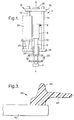
- an extrusion head 2 comprises a structural cage 12 of support struts 14, an upper support plate 16 and a lower support plate 18.
- the lower support plate 18 is hollow and contains gears (not shown) used in the transmission system 20.
- An inlet portion 8 is mounted on the support cage 12 (for clarity, the mounting are not shown) and has an inlet 9 for coupling the inlet portion 8 of the head 2 to a supply of the material to be extruded. The material will usually be supplied to the head through the inlet 9 by a hose (not shown).
- a hollow shaft 6 is coupled to the inlet portion 8 by means of a rotation joint 10 which allows the shaft to rotate, relative to the inlet portion 8, about a rotation axis A.
- the rotation axis A coincides with the longitudinal axis of the nozzle 4 and the shaft 6.
- the hollow shaft 6 ends with an extrusion nozzle 4 through which the profile (not shown) may be extruded.
- the internal arrangement of inlet portion 8, shaft 6 and extrusion nozzle 4 is such that material to be extruded will, under pressure, flow from the inlet portion 8 through the shaft 6 (whether stationary or rotating relative to the inlet portion 8) and through extrusion nozzle 4.
- the hollow shaft 6 is coupled by a transmission system 20 (part of which hidden in Figure 1 by lower support plate 18) to an electric motor 22 which drives the rotation of shaft 6 and nozzle 4.
- the shaft 6 rotates in a collar 24 where the shaft passes through the lower support plate 18.
- a pantograph shock absorber 26 (which comprises a spring mechanism not shown in Fig. 1) is coupled to the shaft 6 between the collar 24 and the nozzle 4.
- the pantograph 26 is used to keep the pressure of the nozzle 4 against the glass surface constant and thus to maintain a constant distance between the nozzle and the glass surface, independently of any imperfection (e.g. waviness) of the glass edge.
- the areas of the extrusion head 2 which will be in contact with the material to be extruded, especially the inlet 9, inlet portion 8, shaft 6 and nozzle 4 are thermo-regulated by heaters (not shown) capable of maintaining a pre-determined temperature in the range room temperature to about 300° C.
- heaters not shown
- the other components of the extrusion head 2 which are not heated (and/or which may be adversely affected by heat) will usually be insulated.
- the extrusion head 2 as shown in Figure 1 is fixed to the mounting flange 28 of the operating arm of a robot.
- the robot is used to drive the extrusion head over the desired extrusion path.
- Typical commercially available robots have six rotation axes.
- the extrusion head 2 when fixed to a commercially available robot provides a seventh and independent (i.e. separate to other axes of rotation, for example, the rotation axes of the robot) rotation axis for improved flexibility and control of extrusion, especially around sharp corners of glazings.
- the robot will be used to control the rotation of the nozzle 4 of the extrusion head 2 by connecting the motor 22 to the robot (not shown).
- the axis A will usually be maintained substantially orthogonal to the surface of the glazing. However, it may be advantageous to vary the angle between the axis (i.e. the independent rotation axis) and the surface of the glazing so as to provide finer control over the extruded profile.
- a sheet of glass 30 intended as a vehicle glazing has substantially the shape of a trapezium (in practice, the glazing 30 will be bent (i.e. curved) and, in consequence will have slightly curved edges).
- An extrusion nozzle 4 (for clarity only the extrusion nozzle 4 of the extrusion head 2 is shown in Figure 2) is driven along the lower edge 32 of the sheet of glass 30 by a robot (not shown).
- a polymer profile 34 of a vulcanised thermoplastic elastomer (obtained from So.F.Tter Srl and supplied under the trade name FORPRENE) is extruded along the lower edge 32 by the extrusion nozzle 4 until the nozzle 4 has reached the corner 36 of the sheet of glass 30 (referring to Figure 2b).
- the extrusion nozzle 4 is rotated so that it is orientated to an extrusion path along the right side edge 38 of the sheet of glass 30.
- the robot drives the extrusion nozzle 4, and the nozzle 4 extrudes polymer profile 34, along the right side edge 38.
- polymer profile 34 is extruded continuously from the extrusion nozzle 4 whilst it is driven along the lower edge 32, around the corner 36 and along the right side edge 38 so that a continuous polymer profile 34 is extruded along those edges and around the sharp corner 36.
- the polymer profile 34 will be seamless around the corner and the portions of the profile before, around and after the corner will have substantially the same material properties including substantially the same adhesion properties.
- a polymer profile 40 extruded on to the edge of a vehicle glazing 42 comprises a lip portion 44 projecting over the edge of the glazing and a spacing portion 46 projecting substantially vertically from the surface of the glazing 42.
- the spacing portion 46 is intended to space the glazing 42 from the vehicle body.
- the lip portion 44 is intended to contact an opposed part of the vehicle boy and bend around the edge of the glazing 42 so as to space the glazing efficiently in the opening provided in the vehicle body, form an improved weather seal and to protect the edge of the glazing 42.
- the polymer profile comprises a vulcanised thermoplastic elastomer but may alternatively be formed by extrusion using any other material known to be suitable for extruding profiles on to glazings, for example, polyurethane.
Landscapes
- Engineering & Computer Science (AREA)
- Mechanical Engineering (AREA)
- Manufacturing & Machinery (AREA)
- Extrusion Moulding Of Plastics Or The Like (AREA)
- Manufacture, Treatment Of Glass Fibers (AREA)
Priority Applications (11)
| Application Number | Priority Date | Filing Date | Title |
|---|---|---|---|
| EP01830147A EP1236559A1 (fr) | 2001-03-02 | 2001-03-02 | Dispositif et procédé d'extrusion d'un profile à la périphérie de la surface d'un vitrage et un vitrage pourvu d'un cadre profilé |
| AT02748321T ATE393692T1 (de) | 2001-03-02 | 2002-02-26 | Vorrichtung und verfahren zum extrudieren eines profils auf einer verglasung |
| CNB028059077A CN1239308C (zh) | 2001-03-02 | 2002-02-26 | 在窗玻璃上挤压异型件的装置和方法及其生成的窗玻璃 |
| DE60226311T DE60226311T2 (de) | 2001-03-02 | 2002-02-26 | Vorrichtung und verfahren zum extrudieren eines profils auf einer verglasung |
| ES02748321T ES2305264T3 (es) | 2001-03-02 | 2002-02-26 | Aparato y procedimiento para extruir un perfil sobre un cristal. |
| US10/469,595 US7404711B2 (en) | 2001-03-02 | 2002-02-26 | Apparatus for extruding a profile on a glazing |
| EP02748321A EP1368176B1 (fr) | 2001-03-02 | 2002-02-26 | Appareil et procede servant a extruder un profil sur un vitrage |
| BRPI0207666-7A BR0207666B1 (pt) | 2001-03-02 | 2002-02-26 | equipamento para extrudar um perfiil sobre um envidraçamento, e processo e cabeça de extrusão para extrudar um perfil por sobre um envidraçamento. |
| MXPA03007774A MXPA03007774A (es) | 2001-03-02 | 2002-02-26 | Aparato y proceso para extruir un perfil en un encristalado y un encristalado que tiene un perfil extruido. |
| PCT/EP2002/002034 WO2002070229A1 (fr) | 2001-03-02 | 2002-02-26 | Appareil et procede servant a extruder un profil sur un vitrage et vitrage a profil extrude |
| US12/213,552 US20080268198A1 (en) | 2001-03-02 | 2008-06-20 | Process for extruding a profile on a glazing and a glazing having an extruded profile |
Applications Claiming Priority (1)
| Application Number | Priority Date | Filing Date | Title |
|---|---|---|---|
| EP01830147A EP1236559A1 (fr) | 2001-03-02 | 2001-03-02 | Dispositif et procédé d'extrusion d'un profile à la périphérie de la surface d'un vitrage et un vitrage pourvu d'un cadre profilé |
Publications (1)
| Publication Number | Publication Date |
|---|---|
| EP1236559A1 true EP1236559A1 (fr) | 2002-09-04 |
Family
ID=8184429
Family Applications (2)
| Application Number | Title | Priority Date | Filing Date |
|---|---|---|---|
| EP01830147A Withdrawn EP1236559A1 (fr) | 2001-03-02 | 2001-03-02 | Dispositif et procédé d'extrusion d'un profile à la périphérie de la surface d'un vitrage et un vitrage pourvu d'un cadre profilé |
| EP02748321A Expired - Lifetime EP1368176B1 (fr) | 2001-03-02 | 2002-02-26 | Appareil et procede servant a extruder un profil sur un vitrage |
Family Applications After (1)
| Application Number | Title | Priority Date | Filing Date |
|---|---|---|---|
| EP02748321A Expired - Lifetime EP1368176B1 (fr) | 2001-03-02 | 2002-02-26 | Appareil et procede servant a extruder un profil sur un vitrage |
Country Status (9)
| Country | Link |
|---|---|
| US (2) | US7404711B2 (fr) |
| EP (2) | EP1236559A1 (fr) |
| CN (1) | CN1239308C (fr) |
| AT (1) | ATE393692T1 (fr) |
| BR (1) | BR0207666B1 (fr) |
| DE (1) | DE60226311T2 (fr) |
| ES (1) | ES2305264T3 (fr) |
| MX (1) | MXPA03007774A (fr) |
| WO (1) | WO2002070229A1 (fr) |
Cited By (1)
| Publication number | Priority date | Publication date | Assignee | Title |
|---|---|---|---|---|
| US7485342B2 (en) * | 2003-06-25 | 2009-02-03 | The Yokohama Rubber Co., Ltd. | Method of forming spacer of double glazing |
Families Citing this family (2)
| Publication number | Priority date | Publication date | Assignee | Title |
|---|---|---|---|---|
| KR101976228B1 (ko) | 2011-09-22 | 2019-05-07 | 가부시키가이샤 한도오따이 에네루기 켄큐쇼 | 광 검출 장치 및 광 검출 장치의 구동 방법 |
| CN105666817B (zh) * | 2016-03-25 | 2018-08-24 | 广州福耀玻璃有限公司 | 胶条挤出装置及方法 |
Citations (7)
| Publication number | Priority date | Publication date | Assignee | Title |
|---|---|---|---|---|
| US5000988A (en) * | 1987-01-14 | 1991-03-19 | Matsushita Electric Industrial Co., Ltd. | Method of applying a coating of viscous materials |
| US5273704A (en) * | 1990-10-04 | 1993-12-28 | Saint-Gobain Vitrage International | Process for extruding a polymer onto a glazing |
| JPH06156337A (ja) * | 1992-11-30 | 1994-06-03 | Asahi Glass Co Ltd | シール材の押出成形方法及び装置 |
| US5336349A (en) * | 1991-07-17 | 1994-08-09 | Saint Gobain Vitrage International | Process and device for the production of an article equipped with a profiled bead |
| US5507994A (en) * | 1993-08-09 | 1996-04-16 | Saint Gobain Vitrage | Process and apparatus for providing a shaped polymer frame on a glass plate |
| DE29613762U1 (de) * | 1996-08-09 | 1996-12-05 | Lenhardt Maschinenbau | Vorrichtung zum Auftragen eines plastischen Abstandhalters auf eine Glastafel |
| WO2000067915A1 (fr) * | 1999-05-07 | 2000-11-16 | Designetics | Station d'appret automatise |
Family Cites Families (22)
| Publication number | Priority date | Publication date | Assignee | Title |
|---|---|---|---|---|
| DE3632327A1 (de) * | 1986-08-30 | 1988-03-17 | Karl Lenhardt | Verfahren zum versiegeln von rechteckigen isolierglasscheiben |
| DE4006006C1 (fr) * | 1990-02-26 | 1991-09-19 | Vegla Vereinigte Glaswerke Gmbh, 5100 Aachen, De | |
| DE4123256C1 (fr) * | 1991-07-13 | 1992-10-08 | Saint Gobain Vitrage | |
| EP0568014B1 (fr) * | 1992-04-28 | 1998-10-21 | Asahi Glass Company Ltd. | Procédé de fabrication d'un vitrage avec un cadre en résine synthétique |
| DE4315469A1 (de) * | 1993-05-10 | 1994-11-17 | Ver Glaswerke Gmbh | Verfahren und Vorrichtung zum Aufextrudieren eines kalibrierten Profilstrangs aus einem thermoplastischen Polymer auf Gegenstände |
| FR2705275B1 (fr) * | 1993-05-13 | 1995-07-21 | Saint Gobain Vitrage Int | Vitrages feuilletés et procédé de fabrication. |
| US5645785A (en) * | 1993-08-09 | 1997-07-08 | Saint Gobain Vitrage | Device for extruding a polymer frame onto a plate-shaped object |
| DE69527663T2 (de) * | 1994-02-28 | 2003-03-13 | Central Glass Co Ltd | Verfahren zur Herstellung von Formlingen auf plattenförmigen Gegenständen mittels Strangpressdüse |
| DE4433749C2 (de) * | 1994-09-22 | 2002-11-21 | Lenhardt Maschinenbau | Verfahren und Vorrichtung zum Auftragen eines plastischen Abstandhalters auf eine Glastafel |
| DE9416684U1 (de) | 1994-10-18 | 1995-01-26 | Lenhardt Maschinenbau | Vorrichtung zum Füllen der Randfuge von Isolierglasscheiben mit einer Versiegelungsmasse |
| DE19503510C2 (de) * | 1995-02-03 | 1996-12-19 | Sekurit Saint Gobain Deutsch | Verfahren zur Herstellung einer IR-reflektierenden Verbundglasscheibe für Kraftfahrzeuge |
| JP3369412B2 (ja) * | 1995-12-05 | 2003-01-20 | 東海興業株式会社 | 押出成形用ダイ装置 |
| DE19632063C1 (de) | 1996-08-09 | 1998-03-12 | Lenhardt Maschinenbau | Verfahren und Vorrichtung zum Auftragen eines plastischen Abstandhalters auf eine Glastafel |
| DE19632062C1 (de) | 1996-08-09 | 1998-03-05 | Lenhardt Maschinenbau | Verfahren und Vorrichtung zum Auftragen eines plastischen Abstandhalters auf eine Glastafel |
| DE19634983C1 (de) | 1996-08-29 | 1998-05-20 | Lenhardt Maschinenbau | Verfahren und Vorrichtung zum Auftragen eines plastischen Abstandhalters für Isolierglasscheiben auf eine Glastafel |
| US5876554A (en) * | 1997-06-11 | 1999-03-02 | Lafond; Luc | Apparatus for sealing the corners of insulated glass assemblies |
| US6852186B1 (en) * | 1998-04-20 | 2005-02-08 | Central Glass Co., Ltd. | Method and device for attaching adhesive tape |
| DE19837348C2 (de) * | 1998-08-18 | 2002-04-18 | Saint Gobain Sekurit D Gmbh | Verfahren und Vorrichtung zum Ausformen eines Abschnittes eines auf einen Gegenstand extrudierten Profilstrangs |
| US6776944B2 (en) * | 1999-05-28 | 2004-08-17 | Textron Automotive Company Inc. | Method for applying BSR elastomer |
| US6231327B1 (en) * | 1999-07-02 | 2001-05-15 | Mastercraft Industries, L.P. | Composite extrusion and patterning machine for irregularly curved edges and method of manufacture thereof |
| US6558146B1 (en) * | 2000-10-10 | 2003-05-06 | Delphi Technologies, Inc. | Extrusion deposition molding with in-line compounding of reinforcing fibers |
| US6494245B1 (en) * | 2000-10-30 | 2002-12-17 | Albert A. Simone | Apparatus for automatically and continuously applying sealant material in an insulated glass assembly |
-
2001
- 2001-03-02 EP EP01830147A patent/EP1236559A1/fr not_active Withdrawn
-
2002
- 2002-02-26 WO PCT/EP2002/002034 patent/WO2002070229A1/fr active IP Right Grant
- 2002-02-26 BR BRPI0207666-7A patent/BR0207666B1/pt not_active IP Right Cessation
- 2002-02-26 US US10/469,595 patent/US7404711B2/en not_active Expired - Fee Related
- 2002-02-26 CN CNB028059077A patent/CN1239308C/zh not_active Expired - Fee Related
- 2002-02-26 DE DE60226311T patent/DE60226311T2/de not_active Expired - Lifetime
- 2002-02-26 ES ES02748321T patent/ES2305264T3/es not_active Expired - Lifetime
- 2002-02-26 MX MXPA03007774A patent/MXPA03007774A/es active IP Right Grant
- 2002-02-26 EP EP02748321A patent/EP1368176B1/fr not_active Expired - Lifetime
- 2002-02-26 AT AT02748321T patent/ATE393692T1/de not_active IP Right Cessation
-
2008
- 2008-06-20 US US12/213,552 patent/US20080268198A1/en not_active Abandoned
Patent Citations (7)
| Publication number | Priority date | Publication date | Assignee | Title |
|---|---|---|---|---|
| US5000988A (en) * | 1987-01-14 | 1991-03-19 | Matsushita Electric Industrial Co., Ltd. | Method of applying a coating of viscous materials |
| US5273704A (en) * | 1990-10-04 | 1993-12-28 | Saint-Gobain Vitrage International | Process for extruding a polymer onto a glazing |
| US5336349A (en) * | 1991-07-17 | 1994-08-09 | Saint Gobain Vitrage International | Process and device for the production of an article equipped with a profiled bead |
| JPH06156337A (ja) * | 1992-11-30 | 1994-06-03 | Asahi Glass Co Ltd | シール材の押出成形方法及び装置 |
| US5507994A (en) * | 1993-08-09 | 1996-04-16 | Saint Gobain Vitrage | Process and apparatus for providing a shaped polymer frame on a glass plate |
| DE29613762U1 (de) * | 1996-08-09 | 1996-12-05 | Lenhardt Maschinenbau | Vorrichtung zum Auftragen eines plastischen Abstandhalters auf eine Glastafel |
| WO2000067915A1 (fr) * | 1999-05-07 | 2000-11-16 | Designetics | Station d'appret automatise |
Non-Patent Citations (1)
| Title |
|---|
| PATENT ABSTRACTS OF JAPAN vol. 018, no. 483 (M - 1670) 8 September 1994 (1994-09-08) * |
Cited By (1)
| Publication number | Priority date | Publication date | Assignee | Title |
|---|---|---|---|---|
| US7485342B2 (en) * | 2003-06-25 | 2009-02-03 | The Yokohama Rubber Co., Ltd. | Method of forming spacer of double glazing |
Also Published As
| Publication number | Publication date |
|---|---|
| EP1368176B1 (fr) | 2008-04-30 |
| EP1368176A1 (fr) | 2003-12-10 |
| WO2002070229A1 (fr) | 2002-09-12 |
| CN1239308C (zh) | 2006-02-01 |
| ES2305264T3 (es) | 2008-11-01 |
| ATE393692T1 (de) | 2008-05-15 |
| US20040126528A1 (en) | 2004-07-01 |
| BR0207666A (pt) | 2004-04-27 |
| CN1498157A (zh) | 2004-05-19 |
| BR0207666B1 (pt) | 2011-05-31 |
| DE60226311D1 (de) | 2008-06-12 |
| MXPA03007774A (es) | 2004-11-12 |
| DE60226311T2 (de) | 2009-05-20 |
| US7404711B2 (en) | 2008-07-29 |
| US20080268198A1 (en) | 2008-10-30 |
Similar Documents
| Publication | Publication Date | Title |
|---|---|---|
| JP3353914B2 (ja) | 異形縁取材を備えた物品の製造方法及び装置 | |
| US5057265A (en) | Method of making a spacer for a windshield bracket | |
| US6293609B1 (en) | Vehicular window assembly | |
| US5864996A (en) | Gasketed panel | |
| US5421940A (en) | Process for the production of an automobile pane equipped with an elastomer frame of a predetermined shape | |
| KR0160497B1 (ko) | 복합 압출물 및 그 제조방법 | |
| EP0576179A1 (fr) | Assemblage d'un panneau de véhicule | |
| US6203639B1 (en) | Vehicle assembly line-side heat activation of a “ready-to-install” window fixing adhesive for attachment of a vehicle window to a vehicle | |
| US6521083B1 (en) | Vehicle assembly line-side heat activation of a “ready-to-install” window fixing adhesive for attachment of a vehicle window to a vehicle | |
| US6089646A (en) | Vehicular window assembly | |
| CZ219092A3 (en) | Window with circumferential frame made of a section extruded from a polymer, a process for producing such window and apparatus for making the same | |
| IE910616A1 (en) | Apparatus for extruding an extruded section onto the edge¹area of the surface of a glass plate | |
| JPH07179122A (ja) | 枠体付きガラスパネル | |
| US20080268198A1 (en) | Process for extruding a profile on a glazing and a glazing having an extruded profile | |
| EP0672513B1 (fr) | Procédé d'extrusion d'un produit moulé sur des articles en formes de plaques | |
| KR20010024490A (ko) | 물체 상에 압출 성형된 스트링 테두리 부분의 노-작업에의한 생산 방법과 장치, 및 상기와 같은 물체를 포함하는물품 | |
| EP1346820A1 (fr) | Procédé pour la fabrication d'un vitrage | |
| JP3199197B2 (ja) | 枠体付きパネルの製造法 | |
| JP3178642B2 (ja) | 押出成形用ノズル及び枠体付き板状体の製造方法 | |
| JPH0687146A (ja) | 枠体付きパネルの製造方法 | |
| JP3490485B2 (ja) | モールの装着方法およびその装置 | |
| JPH08244091A (ja) | 合成樹脂枠体付き窓体の製造方法 | |
| JPH08174624A (ja) | 枠体付きパネル及びその製造法 | |
| JP2000326390A (ja) | ウインドウモールの製造装置及び製造方法 | |
| JPH08252855A (ja) | 合成樹脂枠体付き窓体の製造方法 |
Legal Events
| Date | Code | Title | Description |
|---|---|---|---|
| PUAI | Public reference made under article 153(3) epc to a published international application that has entered the european phase |
Free format text: ORIGINAL CODE: 0009012 |
|
| AK | Designated contracting states |
Kind code of ref document: A1 Designated state(s): AT BE CH CY DE DK ES FI FR GB GR IE IT LI LU MC NL PT SE TR |
|
| AX | Request for extension of the european patent |
Free format text: AL;LT;LV;MK;RO;SI |
|
| RAP1 | Party data changed (applicant data changed or rights of an application transferred) |
Owner name: N.K.E. S.P.A. Owner name: PILKINGTON ITALIA S.P.A. |
|
| AKX | Designation fees paid | ||
| REG | Reference to a national code |
Ref country code: DE Ref legal event code: 8566 |
|
| STAA | Information on the status of an ep patent application or granted ep patent |
Free format text: STATUS: THE APPLICATION IS DEEMED TO BE WITHDRAWN |
|
| 18D | Application deemed to be withdrawn |
Effective date: 20030305 |