EP1232929B1 - Sicherheitslenksäule - Google Patents
Sicherheitslenksäule Download PDFInfo
- Publication number
- EP1232929B1 EP1232929B1 EP02002615A EP02002615A EP1232929B1 EP 1232929 B1 EP1232929 B1 EP 1232929B1 EP 02002615 A EP02002615 A EP 02002615A EP 02002615 A EP02002615 A EP 02002615A EP 1232929 B1 EP1232929 B1 EP 1232929B1
- Authority
- EP
- European Patent Office
- Prior art keywords
- steering column
- jacket tube
- connecting element
- safety steering
- accordance
- Prior art date
- Legal status (The legal status is an assumption and is not a legal conclusion. Google has not performed a legal analysis and makes no representation as to the accuracy of the status listed.)
- Expired - Lifetime
Links
- 238000006073 displacement reaction Methods 0.000 description 13
- 238000003825 pressing Methods 0.000 description 4
- 230000008901 benefit Effects 0.000 description 3
- 230000009471 action Effects 0.000 description 2
- 230000005489 elastic deformation Effects 0.000 description 2
- 238000004904 shortening Methods 0.000 description 2
- 230000037213 diet Effects 0.000 description 1
- 235000005911 diet Nutrition 0.000 description 1
- 238000005265 energy consumption Methods 0.000 description 1
- 238000009434 installation Methods 0.000 description 1
- 230000007246 mechanism Effects 0.000 description 1
- 238000000034 method Methods 0.000 description 1
- 230000037361 pathway Effects 0.000 description 1
- 230000008569 process Effects 0.000 description 1
- 230000002441 reversible effect Effects 0.000 description 1
Images

Classifications
-
- B—PERFORMING OPERATIONS; TRANSPORTING
- B62—LAND VEHICLES FOR TRAVELLING OTHERWISE THAN ON RAILS
- B62D—MOTOR VEHICLES; TRAILERS
- B62D1/00—Steering controls, i.e. means for initiating a change of direction of the vehicle
- B62D1/02—Steering controls, i.e. means for initiating a change of direction of the vehicle vehicle-mounted
- B62D1/16—Steering columns
- B62D1/18—Steering columns yieldable or adjustable, e.g. tiltable
- B62D1/19—Steering columns yieldable or adjustable, e.g. tiltable incorporating energy-absorbing arrangements, e.g. by being yieldable or collapsible
- B62D1/192—Yieldable or collapsible columns
Definitions
- the invention relates to a safety steering column for a motor vehicle arranged with a concentric to a steering shaft, attached to the vehicle body casing tube, the at an axial impact action while absorbing energy can be shortened is, wherein the jacket tube of two, different diameters having, partially nested casing pipe parts consists.
- Axial sliding systems for steering columns are in very different Variants known. They serve in an accident and a thereby caused impact of the vehicle occupant on the Indulge steering wheel while absorbing impact energy. Their principle of action is based on that one to a predetermined axial load of the steering column designed locking member at an excess of the predetermined load releases, so that the interconnected via the securing member components be pushed together by absorbing energy can.
- a safety steering column known for a motor vehicle having a jacket tube with having two partially nested casing pipes.
- the nested parts of the jacket tube are in certain Conically shaped areas. In the one formed by these areas is the same wide cone-shaped space arranged a number of elastic deformation rings.
- a disadvantage of this known safety steering column is that the displacement force between the two casing pipe parts not adjusted or not adapted to the particular application can be without the components themselves being changed.
- the force / path course when pushing together the casing pipe parts is also not constant, but falls in one for the Driver unfavorable way over the pathway strong. in addition comes that between the two casing pipe parts no fuse against a radial displacement of the casing tube parts against each other is provided.
- the present invention is the Task is based, a safety steering column for a motor vehicle to create with a shortenable jacket tube, in which the Displacement force set between the two casing pipe parts can be.
- a safety steering column for a motor vehicle with the features of the claim 1 solved.
- the invention is characterized from that the safety steering column concentric to a Steering spindle arranged, attached to the vehicle body Jacket tube having under an axial impact under Energy consumption can be shortened, wherein the jacket tube of two different diameter, partly nested Jacket pipe parts consists.
- the connecting element is attached to one of the casing tube parts and in an introduced into the other casing pipe part groove pressed with a predetermined force.
- the adjustment of the displacement force is in particular of Advantage if the steering spindle surrounded by the jacket tube also designed to slide into each other and designed so that they while absorbing energy. Then, namely, the displacement force of the jacket tube in the assembly process individually on the measured Actual value of one located in the steering column strand Crash element can be adjusted so that the safety steering column optimally designed.
- the displacement force of the safety steering column according to the invention is constant over the way. It means that regardless of how far the two parts of the jacket tube pushed into each other, the displacement force always the same is.
- Another advantage of the invention is the fact that the Crash system is reversible, that means that once at a Crash collapsed casing pipe pulled apart again and can be adjusted via the crash element.
- the groove in a the casing pipe parts and the engaging in the groove connecting element relative to a sectional plane perpendicular to a longitudinal axis is aligned through both casing pipe parts, a conical cross-sectional area, so that after pressing of the connecting element in the groove a positive Connection arises and thus in the radial direction no play between the two casing pipe parts.
- This is important, because at the pointing in the vehicle interior casing pipe part Controls are attached, such as the lever for Operation of the turn signal. A force on this lever should not affect the system of the safety steering column that, for example, a casing pipe part relative to the another is moved. This is due to the radial backlash avoided due to the conical embodiment.
- the connecting element pressed into the conical groove by means of at least one screw.
- the groove is introduced into the outer wall of the casing pipe part, which has the smaller diameter. Corresponding engages the screw with its thread into a thread the casing pipe part, which has the larger diameter.
- a slider as a connecting element, in which at least the surface on which the two casing pipe parts slide against each other in case of pushing together, has a defined roughness, so that the frictional force between the two casing pipe parts after tightening the Screw can be determined exactly.
- a slider can also the surface of the groove, that is their roughness on the Be matched surface of the slider. Preferred are both surfaces flat and smooth. In this way the displacement force can be reliably adjusted.
- Fig. 1 is a longitudinal section through a safety steering column according to the invention 1 shown.
- the steering column 1 has a Steering spindle 2 on.
- the mechanism is for axial shortening of the steering shaft 2 not shown. This can be designed according to the solutions known from the prior art his.
- the steering column 1 also has a jacket tube 3, which consists of a Part 3a with a larger diameter and a part 3b with a smaller diameter.
- the two casing pipe parts 3a and 3b are partially in the area 4 in each other. In this Area they communicate with each other.
- the casing pipe part 3a is connected via a connection, not shown on the Vehicle body attached.
- the casing pipe part 3b indicates his facing away from the casing tube part 3a end storage 5, which is a rotation of the steering shaft 2 in the casing tube 3 guaranteed.
- the casing pipe part 3b points into the vehicle interior and serves among other things the attachment of controls, such as a turn signal.
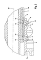
- connection of the two casing pipe parts 3a and 3b takes place via a connecting element in the form of a slider 6.
- a connecting element in the form of a slider 6.
- this groove 7 is the slider 6. It is about screws 8 on the outside Jacket tube part 3a defined.
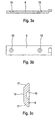
- the slider 6 and the groove 7 have a conical cross section, if you start from a section plane 15, the vertical aligned to a longitudinal axis 14 of the jacket tube 3 is. This is apparent from Fig. 3c, in which such a cross section of the slider 6 is shown. Fig. 3c can also the conical recess 13 are removed, in which the Heads 12 of the screws 8 engage. Figs. 3a and 3b illustrate as the recesses 13 on the slider 6 to each other are arranged.
- the surface 16 of the slider 6 may be designed so that a given roughness is set. The same applies to the conical surfaces 17 and the corresponding surfaces of the groove 7. Over the surfaces 16 and 17 of the slider 6 slip the Jacket tube parts 3a and 3b in the case of axial displacement on each other.
Landscapes
- Engineering & Computer Science (AREA)
- Chemical & Material Sciences (AREA)
- Combustion & Propulsion (AREA)
- Transportation (AREA)
- Mechanical Engineering (AREA)
- Steering Controls (AREA)
Description
- Fig.1:
- einen Längsschnitt durch eine erfihdungsgemäße Sicherheitslenksäule;
- Fig.2:
- eine vergrößerte Detaildarstellung einer Verbindung zwischen zwei Mantelrohrteilen und
- Fig.3:
- eine Draufsicht und zwei Schnittdarstellung eines Verbindungselementes zwischen den zwei Mantelrohrteilen.
Claims (8)
- Sicherheitslenksäule für ein Kraftfahrzeug, mit einem konzentrisch zu einer Lenkspindel angeordneten, an der Fahrzeugkarosserie befestigten Mantelrohr, das bei einer axialen Stoßeinwirkung unter Energieaufnahme verkürzbar ist, wobei das Mantelrohr aus zwei verschiedene Durchmesser aufweisenden, zum Teil ineinander liegenden Mantelrohrteilen besteht,
dadurch gekennzeichnet, daß zwischen den beiden Mantelrohrteilen (3a, 3b) ein Verbindungselement (6) angeordnet ist, wobei das Verbindungselement an einem der Mantelrohrteile (3b) befestigt und in eine in das andere Mantelrohrteil (3a) eingebrachte Nut (7) mit einer vorbestimmten Kraft eingepreßt ist. - Sicherheitslenksäule nach Anspruch 1
dadurch gekennzeichnet, daß die Nut (7) und das Verbindungselement (6) bezogen auf eine Schnittebene, die senkrecht zu einer Längsachse (14) durch beide Mantelrohrteile (3a, 3b) ausgerichtet ist, eine konische Querschnittsfläche aufweisen. - Sicherheitslenksäule nach Anspruch 1 oder 2,
dadurch gekennzeichnet, daß das Verbindungselement (6) mittels mindestens einer Schraube (8) in die Nut (7) gepreßt ist. - Sicherheitslenksäule nach einem der vorhergehenden Ansprüche,
dadurch gekennzeichnet, daß die Schraube (8) ein konisches Ende (12) aufweist, welches in eine entsprechende Ausnehmung (13) in dem Verbindungselement (6) eingreift. - Sicherheitslenksäule nach einem der vorhergehenden Ansprüche,
dadurch gekennzeichnet, daß die Nut (7) in die Außenseite des Mantelrohrteils (3b) mit dem kleineren Durchmesser eingebracht ist. - Sicherheitslenksäule nach Anspruch 4,
dadurch gekennzeichnet, daß die Schraube (8) mit ihrem Gewinde in das Mantelrohrteil (3a) eingreift, das den größeren Durchmesser aufweist. - Sicherheitslenksäule nach einem der vorhergehenden Ansprüche,
dadurch gekennzeichnet, daß das Verbindungselement (6) ein Gleitstück ist. - Sicherheitslenksäule nach Anspruch 7,
dadurch gekennzeichnet, daß zumindest die Oberfläche des Gleitstücks (6) auf der die beiden Mantelrohrteile (3a, 3b) im Falle eines Zusammenschiebens gegeneinander abgleiten, eine definierte Rauigkeit aufweist.
Applications Claiming Priority (2)
| Application Number | Priority Date | Filing Date | Title |
|---|---|---|---|
| DE10107871A DE10107871C2 (de) | 2001-02-20 | 2001-02-20 | Sicherheitslenksäule |
| DE10107871 | 2001-02-20 |
Publications (3)
| Publication Number | Publication Date |
|---|---|
| EP1232929A2 EP1232929A2 (de) | 2002-08-21 |
| EP1232929A3 EP1232929A3 (de) | 2003-12-03 |
| EP1232929B1 true EP1232929B1 (de) | 2004-12-08 |
Family
ID=7674679
Family Applications (1)
| Application Number | Title | Priority Date | Filing Date |
|---|---|---|---|
| EP02002615A Expired - Lifetime EP1232929B1 (de) | 2001-02-20 | 2002-02-05 | Sicherheitslenksäule |
Country Status (4)
| Country | Link |
|---|---|
| US (1) | US6848334B2 (de) |
| EP (1) | EP1232929B1 (de) |
| JP (1) | JP3581136B2 (de) |
| DE (2) | DE10107871C2 (de) |
Families Citing this family (10)
| Publication number | Priority date | Publication date | Assignee | Title |
|---|---|---|---|---|
| FR2863239B1 (fr) * | 2003-12-04 | 2006-03-03 | Nacam France Sas | Dispositif d'absorption d'energie pour colonne de direction |
| GB0328695D0 (en) * | 2003-12-11 | 2004-01-14 | Trw Lucas Varity Electric | A steering column assembly |
| JP4529796B2 (ja) | 2005-05-26 | 2010-08-25 | アイシン精機株式会社 | 衝撃吸収式ステアリング装置 |
| US7497470B2 (en) * | 2005-11-21 | 2009-03-03 | Delphi Technologies, Inc. | Energy absorbing apparatus |
| AU2006323962A1 (en) * | 2005-12-05 | 2007-06-14 | Melchor Daumal Castellon | Intermediate shaft with low sliding load for the steering column of a motor vehicle |
| DE102008005256B4 (de) * | 2008-01-18 | 2009-10-22 | Thyssenkrupp Presta Ag | Lenksäule mit Kunststoffgleithülse |
| DE102008008310B4 (de) | 2008-02-07 | 2020-10-15 | Axel Hebenstreit | Lenksäulenanordnung für einen Kraftwagen |
| KR20100132428A (ko) * | 2009-06-09 | 2010-12-17 | (주) 임팩트 블랙홀 | 압연관 표면 드래그(drag)에 의한 운동 마찰력과 압연력을 이용한 차량충격을 흡수하는 방법 및 이를 이용한 차량충격흡수장치 |
| DE102015216326B4 (de) * | 2015-08-26 | 2016-09-08 | Thyssenkrupp Ag | Motorisch verstellbare Lenksäule für ein Kraftfahrzeug |
| KR102538860B1 (ko) * | 2022-10-25 | 2023-06-01 | 주식회사 세이브라이프 | 도로용 충격흡수시설의 접이식 충격에너지 조절 및 흡수장치 |
Citations (1)
| Publication number | Priority date | Publication date | Assignee | Title |
|---|---|---|---|---|
| DE1755874A1 (de) * | 1968-07-04 | 1972-01-05 | Ford Werke Ag | Sicherheitslenksaeule fuer Kraftfahrzeuge |
Family Cites Families (23)
| Publication number | Priority date | Publication date | Assignee | Title |
|---|---|---|---|---|
| US1541007A (en) * | 1921-07-18 | 1925-06-09 | William H Thiemer | Slip-end spline connection for universal joints and the like |
| GB1113147A (en) * | 1965-12-23 | 1968-05-08 | Bendix Corp | Axially adjustable steering columns |
| GB1120799A (en) * | 1967-02-03 | 1968-07-24 | Ford Motor Co | Collapsible steering columns |
| GB1163861A (en) * | 1967-03-03 | 1969-09-10 | Ford Motor Co | Collapsible Steering Column Assemblies |
| US3491614A (en) * | 1968-07-18 | 1970-01-27 | Bendix Corp | Collapsible steering column |
| US3572751A (en) * | 1969-06-16 | 1971-03-30 | Gen Motors Corp | Dislodgeable screw anchors and installation |
| US4106311A (en) * | 1976-12-13 | 1978-08-15 | The Bendix Corporation | No-lash axially movable steering column |
| US4445708A (en) * | 1983-05-09 | 1984-05-01 | General Motors Corporation | Energy absorbing steering column for vehicles |
| US4627306A (en) * | 1985-01-07 | 1986-12-09 | Ford Motor Company | Energy absorbing steering column for motor vehicles |
| GB8910882D0 (en) * | 1989-05-11 | 1989-06-28 | Torrington Co | Vehicle steering column incorporating means to decouple it |
| DE4017965C2 (de) * | 1989-06-15 | 1996-04-11 | Volkswagen Ag | Drehfeste Verbindung für zwei teleskopierende Hohlrohrteile, insbesondere Mantelrohrteile einer Sicherheitslenksäule |
| US4949992A (en) * | 1989-09-01 | 1990-08-21 | Ford Motor Company | Collapsible steering column |
| DE4008481A1 (de) * | 1990-03-16 | 1991-09-19 | Reiche & Co | Als teleskoprohr ausgebildete, vorzugsweise durch handkraft hoehenverstellbare kraftfahrzeuglenksaeule |
| BR9102282A (pt) * | 1990-06-13 | 1992-01-14 | Voith Gmbh J M | Dispositivo para aduzir o comeco de uma folha de papel de baixo para um rolo de rebobinadeira |
| FR2674646B1 (fr) * | 1991-03-28 | 1993-12-24 | Ecia | Dispositif de rattrapage des jeux d'assemblage entre deux organes tubulaires deplacables a coulissement l'un dans l'autre, et arbre de direction de vehicule automobile en comportant application. |
| US5115691A (en) * | 1991-09-03 | 1992-05-26 | General Motors Corporation | Collapsible shaft assembly |
| US5560257A (en) * | 1994-06-14 | 1996-10-01 | The Torrington Company | Separable connecting device for a steering column |
| US5590565A (en) * | 1995-02-08 | 1997-01-07 | General Motors Corporation | Motor vehicle steering column |
| DE19518130C2 (de) | 1995-05-17 | 1997-05-15 | Lemfoerder Metallwaren Ag | Sicherheitslenksäule eines Kraftfahrzeuges |
| US5706704A (en) * | 1996-03-25 | 1998-01-13 | General Motors Corporation | Energy absorbing steering column for motor vehicle |
| JPH109277A (ja) | 1996-06-25 | 1998-01-13 | Toyota Motor Corp | シャフトの収縮構造 |
| US5709605A (en) * | 1996-12-23 | 1998-01-20 | General Motors Corporation | Shaft coupling |
| JP2000087991A (ja) * | 1998-07-13 | 2000-03-28 | Nippon Seiko Kk | 伸縮自在シャフトの結合構造 |
-
2001
- 2001-02-20 DE DE10107871A patent/DE10107871C2/de not_active Expired - Fee Related
-
2002
- 2002-02-05 DE DE2002501700 patent/DE50201700D1/de not_active Expired - Fee Related
- 2002-02-05 EP EP02002615A patent/EP1232929B1/de not_active Expired - Lifetime
- 2002-02-19 JP JP2002042056A patent/JP3581136B2/ja not_active Expired - Fee Related
- 2002-02-20 US US10/078,155 patent/US6848334B2/en not_active Expired - Fee Related
Patent Citations (1)
| Publication number | Priority date | Publication date | Assignee | Title |
|---|---|---|---|---|
| DE1755874A1 (de) * | 1968-07-04 | 1972-01-05 | Ford Werke Ag | Sicherheitslenksaeule fuer Kraftfahrzeuge |
Also Published As
| Publication number | Publication date |
|---|---|
| DE10107871C2 (de) | 2003-07-17 |
| JP2002249054A (ja) | 2002-09-03 |
| DE10107871A1 (de) | 2002-09-05 |
| US6848334B2 (en) | 2005-02-01 |
| EP1232929A2 (de) | 2002-08-21 |
| US20020124676A1 (en) | 2002-09-12 |
| JP3581136B2 (ja) | 2004-10-27 |
| DE50201700D1 (de) | 2005-01-13 |
| EP1232929A3 (de) | 2003-12-03 |
Similar Documents
| Publication | Publication Date | Title |
|---|---|---|
| DE19820043C2 (de) | Schwenk- und Teleskopvorrichtung für eine Lenksäule | |
| DE1630857C3 (de) | Sicherheitslenksäule | |
| DE102005034952B3 (de) | Verstellbare Lenksäule für ein Kraftfahrzeug | |
| EP3242827B1 (de) | Lenksäule mit flexibel montierbarem lagersitz | |
| DE102008054363A1 (de) | Lenksäulenanordnung | |
| DE19518130C2 (de) | Sicherheitslenksäule eines Kraftfahrzeuges | |
| DE29924278U1 (de) | Radschützer für Zweiräder | |
| EP3908499B1 (de) | Lenksäule für ein kraftfahrzeug | |
| EP3122612B1 (de) | Lenksäule für ein kraftfahrzeug | |
| DE19859238A1 (de) | Kraftfahrzeugsitz | |
| WO2016110336A1 (de) | Lenksäule mit adaptierbarer schwenklagerung | |
| DE1950062B2 (de) | Sicherheitslenkvorrichtung fuer kraftfahrzeuge | |
| DE10107871C2 (de) | Sicherheitslenksäule | |
| DE2321915A1 (de) | Zusammenschiebbare lenksaeulenanordnung | |
| DE4242119C2 (de) | Teleskoprohranordnung | |
| DE112019005339T5 (de) | Lenksäulenvorrichtung | |
| DE10294486B4 (de) | Aufprallaufnahme-Lenksäuleneinrichtung für Fahrzeuge | |
| DE69713829T2 (de) | Stossenergieaufnehmende Lenksäuleneinrichtung,insbesondere für ein Kraftfahrzeug | |
| EP4021785B1 (de) | Teleskopierbare sattelstütze | |
| WO2005028280A1 (de) | Lenksäulenanordnung mit einer in ihrer neigung und länge veränderbaren lenksäule | |
| DE8308038U1 (de) | Lenksaeule mit einstellbar daran befestigtem lenkrad | |
| EP3625109B1 (de) | Teleskopierbare lenkwelle für ein kraftfahrzeug | |
| WO2005028281A1 (de) | Lenksäulenanordnung mit einer in ihrer neigung und länge veränderbaren lenksäule | |
| DE102004024876B4 (de) | Lenksäulenanordnung mit einer in ihrer Neigung und Länge veränderbaren Lenksäule | |
| DE1925950C3 (de) | StoBdämpfeinrichtung, insbesondere für Sicherheitslenksäulen von Kraftfahrzeugen |
Legal Events
| Date | Code | Title | Description |
|---|---|---|---|
| PUAI | Public reference made under article 153(3) epc to a published international application that has entered the european phase |
Free format text: ORIGINAL CODE: 0009012 |
|
| AK | Designated contracting states |
Kind code of ref document: A2 Designated state(s): AT BE CH CY DE DK ES FI FR GB GR IE IT LI LU MC NL PT SE TR |
|
| AX | Request for extension of the european patent |
Free format text: AL;LT;LV;MK;RO;SI |
|
| PUAL | Search report despatched |
Free format text: ORIGINAL CODE: 0009013 |
|
| AK | Designated contracting states |
Kind code of ref document: A3 Designated state(s): AT BE CH CY DE DK ES FI FR GB GR IE IT LI LU MC NL PT SE TR |
|
| AX | Request for extension of the european patent |
Extension state: AL LT LV MK RO SI |
|
| RIC1 | Information provided on ipc code assigned before grant |
Ipc: 7F 16F 7/09 B Ipc: 7B 62D 1/19 A |
|
| 17P | Request for examination filed |
Effective date: 20031024 |
|
| GRAP | Despatch of communication of intention to grant a patent |
Free format text: ORIGINAL CODE: EPIDOSNIGR1 |
|
| AKX | Designation fees paid |
Designated state(s): DE ES FR GB IT SE |
|
| GRAS | Grant fee paid |
Free format text: ORIGINAL CODE: EPIDOSNIGR3 |
|
| GRAA | (expected) grant |
Free format text: ORIGINAL CODE: 0009210 |
|
| AK | Designated contracting states |
Kind code of ref document: B1 Designated state(s): DE ES FR GB IT SE |
|
| PG25 | Lapsed in a contracting state [announced via postgrant information from national office to epo] |
Ref country code: IT Free format text: LAPSE BECAUSE OF FAILURE TO SUBMIT A TRANSLATION OF THE DESCRIPTION OR TO PAY THE FEE WITHIN THE PRESCRIBED TIME-LIMIT;WARNING: LAPSES OF ITALIAN PATENTS WITH EFFECTIVE DATE BEFORE 2007 MAY HAVE OCCURRED AT ANY TIME BEFORE 2007. THE CORRECT EFFECTIVE DATE MAY BE DIFFERENT FROM THE ONE RECORDED. Effective date: 20041208 |
|
| REG | Reference to a national code |
Ref country code: GB Ref legal event code: FG4D Free format text: NOT ENGLISH |
|
| REG | Reference to a national code |
Ref country code: SE Ref legal event code: TRGR |
|
| REG | Reference to a national code |
Ref country code: IE Ref legal event code: FG4D Free format text: GERMAN |
|
| REF | Corresponds to: |
Ref document number: 50201700 Country of ref document: DE Date of ref document: 20050113 Kind code of ref document: P |
|
| PGFP | Annual fee paid to national office [announced via postgrant information from national office to epo] |
Ref country code: SE Payment date: 20050210 Year of fee payment: 4 Ref country code: FR Payment date: 20050210 Year of fee payment: 4 |
|
| PG25 | Lapsed in a contracting state [announced via postgrant information from national office to epo] |
Ref country code: ES Free format text: LAPSE BECAUSE OF FAILURE TO SUBMIT A TRANSLATION OF THE DESCRIPTION OR TO PAY THE FEE WITHIN THE PRESCRIBED TIME-LIMIT Effective date: 20050319 |
|
| GBT | Gb: translation of ep patent filed (gb section 77(6)(a)/1977) |
Effective date: 20050225 |
|
| ET | Fr: translation filed | ||
| PLBE | No opposition filed within time limit |
Free format text: ORIGINAL CODE: 0009261 |
|
| STAA | Information on the status of an ep patent application or granted ep patent |
Free format text: STATUS: NO OPPOSITION FILED WITHIN TIME LIMIT |
|
| 26N | No opposition filed |
Effective date: 20050909 |
|
| PG25 | Lapsed in a contracting state [announced via postgrant information from national office to epo] |
Ref country code: GB Free format text: LAPSE BECAUSE OF NON-PAYMENT OF DUE FEES Effective date: 20060205 |
|
| PG25 | Lapsed in a contracting state [announced via postgrant information from national office to epo] |
Ref country code: SE Free format text: LAPSE BECAUSE OF NON-PAYMENT OF DUE FEES Effective date: 20060206 |
|
| PGFP | Annual fee paid to national office [announced via postgrant information from national office to epo] |
Ref country code: DE Payment date: 20060214 Year of fee payment: 5 |
|
| EUG | Se: european patent has lapsed | ||
| GBPC | Gb: european patent ceased through non-payment of renewal fee |
Effective date: 20060205 |
|
| REG | Reference to a national code |
Ref country code: FR Ref legal event code: ST Effective date: 20061031 |
|
| PG25 | Lapsed in a contracting state [announced via postgrant information from national office to epo] |
Ref country code: FR Free format text: LAPSE BECAUSE OF NON-PAYMENT OF DUE FEES Effective date: 20060228 Ref country code: DE Free format text: LAPSE BECAUSE OF NON-PAYMENT OF DUE FEES Effective date: 20070901 |