US4445708A - Energy absorbing steering column for vehicles - Google Patents
Energy absorbing steering column for vehicles Download PDFInfo
- Publication number
- US4445708A US4445708A US06/492,606 US49260683A US4445708A US 4445708 A US4445708 A US 4445708A US 49260683 A US49260683 A US 49260683A US 4445708 A US4445708 A US 4445708A
- Authority
- US
- United States
- Prior art keywords
- tubes
- balls
- energy absorption
- stage
- column
- Prior art date
- Legal status (The legal status is an assumption and is not a legal conclusion. Google has not performed a legal analysis and makes no representation as to the accuracy of the status listed.)
- Expired - Lifetime
Links
- 238000010521 absorption reaction Methods 0.000 claims description 26
- 239000000463 material Substances 0.000 claims description 6
- 239000004033 plastic Substances 0.000 claims description 3
- 230000000295 complement effect Effects 0.000 claims 6
- 239000006096 absorbing agent Substances 0.000 abstract 1
- 239000002184 metal Substances 0.000 description 4
- 229910000831 Steel Inorganic materials 0.000 description 3
- 239000002775 capsule Substances 0.000 description 3
- 239000010959 steel Substances 0.000 description 3
- 239000004677 Nylon Substances 0.000 description 2
- 238000010276 construction Methods 0.000 description 2
- 229920001778 nylon Polymers 0.000 description 2
- 230000008878 coupling Effects 0.000 description 1
- 238000010168 coupling process Methods 0.000 description 1
- 238000005859 coupling reaction Methods 0.000 description 1
- 230000013011 mating Effects 0.000 description 1
- 230000004048 modification Effects 0.000 description 1
- 238000012986 modification Methods 0.000 description 1
Images
Classifications
-
- B—PERFORMING OPERATIONS; TRANSPORTING
- B62—LAND VEHICLES FOR TRAVELLING OTHERWISE THAN ON RAILS
- B62D—MOTOR VEHICLES; TRAILERS
- B62D1/00—Steering controls, i.e. means for initiating a change of direction of the vehicle
- B62D1/02—Steering controls, i.e. means for initiating a change of direction of the vehicle vehicle-mounted
- B62D1/16—Steering columns
- B62D1/18—Steering columns yieldable or adjustable, e.g. tiltable
- B62D1/19—Steering columns yieldable or adjustable, e.g. tiltable incorporating energy-absorbing arrangements, e.g. by being yieldable or collapsible
- B62D1/192—Yieldable or collapsible columns
Definitions
- This invention relates to vehicle steering columns and more particularly to a new and improved energy absorbing steering column capable of effectively absorbing the energy of a wide range of steering column loads causing the column to telescopically collapse to lengths varying with loads.
- a deforming ball unit is operatively interposed between the upper and lower cylindrical metallic mast jackets of a telescopically collapsible steering column.
- the deforming ball unit comprises a cylindrical nylon carrier sleeve in which upper and lower annularly arranged sets of steel balls are rotatably mounted. These balls contact and have interference fit with the outer wall of the lower jacket and the inner wall of the upper jacket.
- the balls may form initial tracks or grooves of predetermined lengths in the walls of either or both of the jackets.
- the deforming balls When installed in a vehicle and when the magnitude of a steering column impact load causes the telescopic movement of the upper mast jacket relative to the lower mast jacket, the deforming balls linearly extend the tracks by working and displacing themetal of the upper and lower jacket as the steering column is collapsed. With the balls working the metal to extend the tracks, the energy of a given load is effectively dissipated at a constant rate until column collapse is terminated.
- the upper and lower jackets are formed with ramps or ramp sections which the balls encounter while forming linear grooves or tracks therein. While encountering the ramps, more material is worked as the balls plow their tracks so that energy absorption is increased as the column is stroked.
- ramps are coined in or otherwise provided on the walls of the upper and lower jackets at the opposite ends of the ball unit respectively coacting with the upper and lower ball sets to provide additional stages of energy absorption within a prescribed length of telescopic collapse.
- column loading may be such that the upper ball sets engage upper ramps in the upper jacket for a second stage of energy absorption.
- energy is absorbed at a progressively increasing rate while the column telescopically collapses. If the load is such that telescoping continues, the lower ball set reaches the lower ramp section in the lower jacket so that energy is absorbed at a third and higher rate in the third stage of energy absorption.
- Another feature, object and advantage of this invention is to provide a new and improved telescopically collapsible energy absorbing steering column having telescopic upper and lower jackets in which deforming ball members cooperate with ramp members of the jackets to provide multiple levels of energy matched with column loads over a foreshortened amount of telescopic collapse.
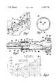
- FIG. 1 is an elevational view of an automotive vehicle body partially broken away to show an energy absorbing steering column assembly operatively mounted therein
- FIG. 2 is an enlarged view with some parts in section of the steering column taken generally along the line 2--2 of FIG. 1;
- FIG. 3 is an enlarged sectional view taken generally along line 3--3 of FIG. 2.
- FIG. 4 is a graph illustrating operation of the steering column of FIGS. 1-3 when stroked on application of a predetermined load directed thereto.
- FIG. 1 illustrates an energy absorbing steering column assembly 10 operatively mounted within an automotive vehicle 12 having a hand wheel 14 which can be manually operated by a vehicle operator for steering the dirigible road wheels of the vehicle.
- the hand wheel 14 is mounted to the upper end of a steering shaft assembly 16 which includes an upper shaft 18 mounted for telescopic movement in a tubular lower shaft 20.
- the upper and lower shafts have conventional mating flats, not shown, so that the two shafts turn together as an assembly when the steering wheel is turned.
- the upper and lower steering shafts are held in an outer position by breakaway plastic connectors 22 which shear on application of predetermined load to the steering shaft assembly to allow these parts to telescopically collapse.
- the lower end of the lower steering shaft is connected through a conventional flexible coupling 26 to a steering gear which in turn is drivingly connected to the dirigible wheels of the vehicle through conventional steering gear linkage, not shown.
- the steering column 10 comprises a mast jacket assembly 28 comprising interfitting upper and lower tubular mast jackets 30 and 32 of steel which have different diameters to telescope together under a wide range of impact loads.
- a mast jacket assembly 28 comprising interfitting upper and lower tubular mast jackets 30 and 32 of steel which have different diameters to telescope together under a wide range of impact loads.
- the upper end portion of the lower jacket slidably fits into the lower end portion of the upper jacket.
- a deforming ball and sleeve assembly 34 Interposed between these end portions.
- This assembly comprises a tubular sleeve 36 of nylon or other suitable material in which upper and lower sets 40, 42 of identical steel balls are rotatably mounted.
- the upper mast jacket has an annular series of identical ramps 46 coined or otherwise provided therein which are axially aligned with and spaced a predetermined distance from the upper ball sets 40.
- the balls of sets 40 can displace ramp metal when tracking so that the rate of energy absorption is increased as the jackets are further telescoped together.
- the lower mast jacket 32 has similarly arcuately spaced and aligned ramps 48 which serve to increase the rate of energy absorption as the lower ball sets 42 roll tracks therein as the column strokes toward its maximum stroke.
- the lower mast jacket 32 is mounted to a front bulkhead 50 in vehicle 12 by conventional bracket construction 52.
- the upper mast jacket 46 has a bracket 54 welded or otherwise affixed thereto which carries release capsules 56. These capsules attach to the lower portion of the instrument panel 58 by bolts 60 such as described in U.S. Pat. No. 3,392,599 issued July 16, 1968 to R. L. White for Energy Absorbing Device which is hereby made of record.
- the capsules On application of a load to the steering wheel exceeding a predetermined load, the capsules release the column which begins to telescope together.
- This action is illustrated by stage 1, segment A-B of the absorption curve of FIG. 4.
- a constant 500 pound load occurs during the first one inch of travel as shown in the chart. During this one inch travel the ball sleeve travels approximately one-half inch.
- the column load increases from 500 pounds, as the upper ball ramps 46 are encountered by the upper ball sets and further telescopic collapse of the steering column assembly occurs.
- E/A Energy absorption
- both the upper and lower ball sets cooperate with the associated ramps to provide for progressively increasing energy absorbing capability so that this steering column assembly provides tailored energy absorption for a wide range of loads from light loads through heavy loads.
Landscapes
- Engineering & Computer Science (AREA)
- Chemical & Material Sciences (AREA)
- Combustion & Propulsion (AREA)
- Transportation (AREA)
- Mechanical Engineering (AREA)
- Steering Controls (AREA)
- Vibration Dampers (AREA)
- Mechanical Control Devices (AREA)
Abstract
Description
Claims (3)
Priority Applications (8)
| Application Number | Priority Date | Filing Date | Title |
|---|---|---|---|
| US06/492,606 US4445708A (en) | 1983-05-09 | 1983-05-09 | Energy absorbing steering column for vehicles |
| CA000438254A CA1192813A (en) | 1983-05-09 | 1983-10-03 | Energy absorbing steering column for vehicles |
| DE8484302164T DE3460665D1 (en) | 1983-05-09 | 1984-03-29 | Energy-absorbing steering column for a vehicle |
| EP84302164A EP0124995B1 (en) | 1983-05-09 | 1984-03-29 | Energy-absorbing steering column for a vehicle |
| AU26432/84A AU556253B2 (en) | 1983-05-09 | 1984-04-04 | Energy absorbing steering column |
| BR8402155A BR8402155A (en) | 1983-05-09 | 1984-05-08 | ENERGY ABSORBING STEERING COLUMN SET FOR A VEHICLE |
| ES532284A ES8504041A1 (en) | 1983-05-09 | 1984-05-08 | Energy-absorbing steering column for a vehicle. |
| JP59091154A JPS6035659A (en) | 1983-05-09 | 1984-05-09 | Energy absorption type steering post assembly for vehicle |
Applications Claiming Priority (1)
| Application Number | Priority Date | Filing Date | Title |
|---|---|---|---|
| US06/492,606 US4445708A (en) | 1983-05-09 | 1983-05-09 | Energy absorbing steering column for vehicles |
Publications (1)
| Publication Number | Publication Date |
|---|---|
| US4445708A true US4445708A (en) | 1984-05-01 |
Family
ID=23956903
Family Applications (1)
| Application Number | Title | Priority Date | Filing Date |
|---|---|---|---|
| US06/492,606 Expired - Lifetime US4445708A (en) | 1983-05-09 | 1983-05-09 | Energy absorbing steering column for vehicles |
Country Status (8)
| Country | Link |
|---|---|
| US (1) | US4445708A (en) |
| EP (1) | EP0124995B1 (en) |
| JP (1) | JPS6035659A (en) |
| AU (1) | AU556253B2 (en) |
| BR (1) | BR8402155A (en) |
| CA (1) | CA1192813A (en) |
| DE (1) | DE3460665D1 (en) |
| ES (1) | ES8504041A1 (en) |
Cited By (28)
| Publication number | Priority date | Publication date | Assignee | Title |
|---|---|---|---|---|
| US4616522A (en) * | 1985-03-08 | 1986-10-14 | Chrysler Corporation | Steering column energy absorbing release bushing and deforming bracket |
| US4805478A (en) * | 1987-06-26 | 1989-02-21 | General Motors Corporation | Steering column for vehicle with multitube energy absorbing mast jacket |
| US4867003A (en) * | 1988-12-19 | 1989-09-19 | General Motors Corporation | Energy absorbing steering column |
| US4886295A (en) * | 1988-12-05 | 1989-12-12 | General Motors Corporation | Vehicle occupant protection system |
| US4991871A (en) * | 1989-12-11 | 1991-02-12 | Nippon Seiko Kabushiki Kaisha | Collapsible steering column apparatus |
| DE4119359A1 (en) * | 1990-06-23 | 1992-01-09 | Gkn Automotive Ag | Fibre-bonded tubular shaft - deforms when vehicle crashes and has energy absorbing characteristics matching bodywork |
| US5081879A (en) * | 1990-05-24 | 1992-01-21 | Ford Motor Company | Steering column assembly mounting bracket |
| US5181589A (en) * | 1990-09-07 | 1993-01-26 | Suspa Compart Ag | Reversible impact damper, in particular for vehicles |
| WO1993004904A1 (en) * | 1991-09-11 | 1993-03-18 | Itt Industries, Inc. | Energy absorbing collapsible steering apparatus |
| FR2704032A1 (en) * | 1993-04-14 | 1994-10-21 | Nadella | Prestressed roller bearing with improved cage and its application in particular to a steering column. |
| GB2278580A (en) * | 1993-06-04 | 1994-12-07 | Gen Motors France | Collapsible steering column assembly. |
| US5427214A (en) * | 1992-07-08 | 1995-06-27 | Suspa Compart Aktiengesellschaft | Impact damper for vehicles |
| US5464251A (en) * | 1992-12-30 | 1995-11-07 | Daumal Castellon; Melchor | Telescopic shaft |
| DE19529370A1 (en) * | 1995-01-28 | 1996-08-01 | Heidemann Werke | Impact absorber |
| US5551727A (en) * | 1993-09-20 | 1996-09-03 | The Torrington Company | Vehicle steering columns |
| US5575501A (en) * | 1994-09-09 | 1996-11-19 | Nsk Ltd. | Shaft for collapsible steering apparatus |
| US5870930A (en) * | 1996-09-03 | 1999-02-16 | Means Industries | Steering column assembly |
| US5911438A (en) * | 1998-03-09 | 1999-06-15 | General Motors Corporation | Energy absorber for steering column |
| US6443491B1 (en) * | 1998-03-20 | 2002-09-03 | Nsk Ltd. | Device for rockably supporting a steering column for a tilt-type steering apparatus |
| US20020124676A1 (en) * | 2001-02-20 | 2002-09-12 | Hans Kluemper | Safety steering column |
| DE4300284C2 (en) * | 1992-07-08 | 2003-10-09 | Suspa Holding Gmbh | impact absorbers |
| US20030227162A1 (en) * | 2002-06-07 | 2003-12-11 | Ulintz Peter J. | Non-linear energy absorbing column assembly |
| DE10328393A1 (en) * | 2003-06-24 | 2005-01-20 | Trw Occupant Restraint Systems Gmbh & Co. Kg | Arrangement for raising engine hood for pedestrian safety has pyrotechnical device for driving final control element in first direction and force limiting device acting in direction opposite to first direction |
| US20050124423A1 (en) * | 2003-12-05 | 2005-06-09 | Ramon Kuczera | Plunging constant velocity joint for a propshaft tuned for energy absorption |
| US20080217900A1 (en) * | 2007-03-08 | 2008-09-11 | Ozsoylu Suat A | Steering column assembly having a stopping member for preventing rotation of a tilt mechanism |
| EP3017115A4 (en) * | 2013-07-02 | 2017-05-17 | The UAB Research Foundation | Systems and methods for absorbing energy |
| US20190111960A1 (en) * | 2017-10-17 | 2019-04-18 | Steering Solutions Ip Holding Corporation | Stowable steering column apparatus |
| US20220396301A1 (en) * | 2021-06-10 | 2022-12-15 | Yamada Manufacturing Co., Ltd. | Steering device |
Families Citing this family (7)
| Publication number | Priority date | Publication date | Assignee | Title |
|---|---|---|---|---|
| US4627306A (en) * | 1985-01-07 | 1986-12-09 | Ford Motor Company | Energy absorbing steering column for motor vehicles |
| JPS6363259U (en) * | 1986-08-05 | 1988-04-26 | ||
| JPH08217Y2 (en) * | 1988-08-09 | 1996-01-10 | 本田技研工業株式会社 | Shock energy absorption type steering device |
| SE9301830D0 (en) * | 1993-05-28 | 1993-05-28 | Ab Astra | NEW COMPOUNDS |
| US5560257A (en) * | 1994-06-14 | 1996-10-01 | The Torrington Company | Separable connecting device for a steering column |
| DE19504036C1 (en) * | 1995-02-08 | 1996-06-27 | Lemfoerder Metallwaren Ag | Safety steering shaft |
| ES2129322B1 (en) * | 1996-04-18 | 2000-02-01 | Castellon Melchor Daumal | IMPROVEMENTS IN TELESCOPIC TREES. |
Citations (4)
| Publication number | Priority date | Publication date | Assignee | Title |
|---|---|---|---|---|
| US3538785A (en) * | 1967-06-12 | 1970-11-10 | Peugeot | Energy absorbing devices |
| US3788148A (en) * | 1972-07-10 | 1974-01-29 | Gen Motors Corp | Energy absorber for collapsible steering columns or the like |
| US3899937A (en) * | 1972-07-14 | 1975-08-19 | Nissan Motor | Collapsible steering column assembly |
| US4006647A (en) * | 1974-08-29 | 1977-02-08 | Toyota Jidosha Kogyo Kabushiki Kaisha | Impact energy absorbing apparatus |
Family Cites Families (6)
| Publication number | Priority date | Publication date | Assignee | Title |
|---|---|---|---|---|
| US3392599A (en) * | 1966-12-30 | 1968-07-16 | Gen Motors Corp | Energy absorbing device |
| GB1209566A (en) * | 1966-12-30 | 1970-10-21 | Gen Motors Corp | Energy absorbers |
| DE1755874C3 (en) * | 1968-07-04 | 1974-05-22 | Ford-Werke Ag, 5000 Koeln | Safety steering column for motor vehicles |
| US3590655A (en) * | 1969-12-01 | 1971-07-06 | Gen Motors Corp | Energy-absorbing steering column |
| JPS5139529B2 (en) * | 1971-08-04 | 1976-10-28 | ||
| US3748922A (en) * | 1972-05-16 | 1973-07-31 | Gen Motors Corp | Energy absorbing steering column |
-
1983
- 1983-05-09 US US06/492,606 patent/US4445708A/en not_active Expired - Lifetime
- 1983-10-03 CA CA000438254A patent/CA1192813A/en not_active Expired
-
1984
- 1984-03-29 DE DE8484302164T patent/DE3460665D1/en not_active Expired
- 1984-03-29 EP EP84302164A patent/EP0124995B1/en not_active Expired
- 1984-04-04 AU AU26432/84A patent/AU556253B2/en not_active Ceased
- 1984-05-08 BR BR8402155A patent/BR8402155A/en not_active IP Right Cessation
- 1984-05-08 ES ES532284A patent/ES8504041A1/en not_active Expired
- 1984-05-09 JP JP59091154A patent/JPS6035659A/en active Pending
Patent Citations (4)
| Publication number | Priority date | Publication date | Assignee | Title |
|---|---|---|---|---|
| US3538785A (en) * | 1967-06-12 | 1970-11-10 | Peugeot | Energy absorbing devices |
| US3788148A (en) * | 1972-07-10 | 1974-01-29 | Gen Motors Corp | Energy absorber for collapsible steering columns or the like |
| US3899937A (en) * | 1972-07-14 | 1975-08-19 | Nissan Motor | Collapsible steering column assembly |
| US4006647A (en) * | 1974-08-29 | 1977-02-08 | Toyota Jidosha Kogyo Kabushiki Kaisha | Impact energy absorbing apparatus |
Cited By (40)
| Publication number | Priority date | Publication date | Assignee | Title |
|---|---|---|---|---|
| US4616522A (en) * | 1985-03-08 | 1986-10-14 | Chrysler Corporation | Steering column energy absorbing release bushing and deforming bracket |
| US4805478A (en) * | 1987-06-26 | 1989-02-21 | General Motors Corporation | Steering column for vehicle with multitube energy absorbing mast jacket |
| US4886295A (en) * | 1988-12-05 | 1989-12-12 | General Motors Corporation | Vehicle occupant protection system |
| US4867003A (en) * | 1988-12-19 | 1989-09-19 | General Motors Corporation | Energy absorbing steering column |
| US4991871A (en) * | 1989-12-11 | 1991-02-12 | Nippon Seiko Kabushiki Kaisha | Collapsible steering column apparatus |
| US5081879A (en) * | 1990-05-24 | 1992-01-21 | Ford Motor Company | Steering column assembly mounting bracket |
| DE4119359A1 (en) * | 1990-06-23 | 1992-01-09 | Gkn Automotive Ag | Fibre-bonded tubular shaft - deforms when vehicle crashes and has energy absorbing characteristics matching bodywork |
| US5181589A (en) * | 1990-09-07 | 1993-01-26 | Suspa Compart Ag | Reversible impact damper, in particular for vehicles |
| US5476284A (en) * | 1991-09-11 | 1995-12-19 | Itt Corporation | Energy absorbing collapsible steering apparatus |
| WO1993004904A1 (en) * | 1991-09-11 | 1993-03-18 | Itt Industries, Inc. | Energy absorbing collapsible steering apparatus |
| DE4300284C2 (en) * | 1992-07-08 | 2003-10-09 | Suspa Holding Gmbh | impact absorbers |
| DE4345550C2 (en) * | 1992-07-08 | 2003-10-09 | Suspa Holding Gmbh | Impact damper attached to vehicle bumper |
| DE4345550C5 (en) * | 1992-07-08 | 2008-06-12 | Suspa Holding Gmbh | impact absorbers |
| US5427214A (en) * | 1992-07-08 | 1995-06-27 | Suspa Compart Aktiengesellschaft | Impact damper for vehicles |
| US5464251A (en) * | 1992-12-30 | 1995-11-07 | Daumal Castellon; Melchor | Telescopic shaft |
| US5413417A (en) * | 1993-04-14 | 1995-05-09 | Nadella | Prestressed rolling bearing with improved cage and its application particularly to a steering column |
| FR2704032A1 (en) * | 1993-04-14 | 1994-10-21 | Nadella | Prestressed roller bearing with improved cage and its application in particular to a steering column. |
| EP0624734A1 (en) * | 1993-04-14 | 1994-11-17 | Nadella | Prestressed roller bearing with improved cage and its use in a car steering column |
| GB2278580B (en) * | 1993-06-04 | 1996-05-29 | Gen Motors France | Collapsible steering column assembly |
| GB2278580A (en) * | 1993-06-04 | 1994-12-07 | Gen Motors France | Collapsible steering column assembly. |
| US5551727A (en) * | 1993-09-20 | 1996-09-03 | The Torrington Company | Vehicle steering columns |
| US5575501A (en) * | 1994-09-09 | 1996-11-19 | Nsk Ltd. | Shaft for collapsible steering apparatus |
| DE19529370A1 (en) * | 1995-01-28 | 1996-08-01 | Heidemann Werke | Impact absorber |
| US5870930A (en) * | 1996-09-03 | 1999-02-16 | Means Industries | Steering column assembly |
| US5911438A (en) * | 1998-03-09 | 1999-06-15 | General Motors Corporation | Energy absorber for steering column |
| US6443491B1 (en) * | 1998-03-20 | 2002-09-03 | Nsk Ltd. | Device for rockably supporting a steering column for a tilt-type steering apparatus |
| US20020124676A1 (en) * | 2001-02-20 | 2002-09-12 | Hans Kluemper | Safety steering column |
| US6848334B2 (en) * | 2001-02-20 | 2005-02-01 | Daimlerchrysler Ag | Safety steering column |
| US20030227162A1 (en) * | 2002-06-07 | 2003-12-11 | Ulintz Peter J. | Non-linear energy absorbing column assembly |
| US6729648B2 (en) * | 2002-06-07 | 2004-05-04 | Sealy Technology Llc | Non-linear energy absorbing column assembly |
| DE10328393A1 (en) * | 2003-06-24 | 2005-01-20 | Trw Occupant Restraint Systems Gmbh & Co. Kg | Arrangement for raising engine hood for pedestrian safety has pyrotechnical device for driving final control element in first direction and force limiting device acting in direction opposite to first direction |
| US7077753B2 (en) * | 2003-12-05 | 2006-07-18 | Gkn Driveline North America, Inc. | Cross groove hybrid plunging constant velocity joint for a propshaft tuned for energy absorption |
| US20050124423A1 (en) * | 2003-12-05 | 2005-06-09 | Ramon Kuczera | Plunging constant velocity joint for a propshaft tuned for energy absorption |
| US20080217900A1 (en) * | 2007-03-08 | 2008-09-11 | Ozsoylu Suat A | Steering column assembly having a stopping member for preventing rotation of a tilt mechanism |
| US7779717B2 (en) * | 2007-03-08 | 2010-08-24 | Gm Global Technology Operations, Inc. | Steering column assembly having a stopping member for preventing rotation of a tilt mechanism |
| EP3017115A4 (en) * | 2013-07-02 | 2017-05-17 | The UAB Research Foundation | Systems and methods for absorbing energy |
| US20190111960A1 (en) * | 2017-10-17 | 2019-04-18 | Steering Solutions Ip Holding Corporation | Stowable steering column apparatus |
| US10882548B2 (en) * | 2017-10-17 | 2021-01-05 | Steering Solutions Ip Holding Corporation | Stowable steering column apparatus |
| US20220396301A1 (en) * | 2021-06-10 | 2022-12-15 | Yamada Manufacturing Co., Ltd. | Steering device |
| US11584425B2 (en) * | 2021-06-10 | 2023-02-21 | Yamada Manufacturing Co., Ltd. | Steering device |
Also Published As
| Publication number | Publication date |
|---|---|
| EP0124995B1 (en) | 1986-09-10 |
| JPS6035659A (en) | 1985-02-23 |
| BR8402155A (en) | 1984-12-18 |
| EP0124995A1 (en) | 1984-11-14 |
| CA1192813A (en) | 1985-09-03 |
| ES532284A0 (en) | 1985-04-01 |
| AU556253B2 (en) | 1986-10-30 |
| ES8504041A1 (en) | 1985-04-01 |
| DE3460665D1 (en) | 1986-10-16 |
| AU2643284A (en) | 1984-11-15 |
Similar Documents
| Publication | Publication Date | Title |
|---|---|---|
| US4445708A (en) | Energy absorbing steering column for vehicles | |
| US4805478A (en) | Steering column for vehicle with multitube energy absorbing mast jacket | |
| US4509386A (en) | Lash-free telescopic steering shaft assembly and method of making the assembly | |
| US3504567A (en) | Collapsible steering shaft construction | |
| US3508633A (en) | Plastically deformable impact absorbing means for vehicles | |
| US4098141A (en) | Energy absorbing steering assembly | |
| US3492888A (en) | Steering assembly for absorbing impact | |
| US3461740A (en) | Collapsible steering column assembly | |
| US4531619A (en) | Collapsible steering column | |
| US3482653A (en) | Shock absorbing device | |
| US4006647A (en) | Impact energy absorbing apparatus | |
| US3612223A (en) | Energy-absorbing device | |
| US3788148A (en) | Energy absorber for collapsible steering columns or the like | |
| US3495474A (en) | Impact absorbing means for vehicles | |
| US4627306A (en) | Energy absorbing steering column for motor vehicles | |
| US4867003A (en) | Energy absorbing steering column | |
| US20070228716A1 (en) | Collapsible steering column assembly and method of operation | |
| KR0139704B1 (en) | Impact absorbing type steering column apparatus with a motorized power steering device | |
| US3401576A (en) | Collapsible steering column | |
| US6754943B1 (en) | Method of manufacturing an axially collapsible driveshaft assembly | |
| US3479902A (en) | Safety steering assembly | |
| US5070741A (en) | Large collapse mini-steering column | |
| GB1597761A (en) | Collapsible steering column | |
| US20050156423A1 (en) | Steering column assembly | |
| US5575501A (en) | Shaft for collapsible steering apparatus |
Legal Events
| Date | Code | Title | Description |
|---|---|---|---|
| AS | Assignment |
Owner name: GENERAL MOTORS CORPORATION A DE CORP. Free format text: ASSIGNMENT OF ASSIGNORS INTEREST.;ASSIGNORS:OAKES, EDMOND G.;ARNDT, FREDERICK P.;GRANDEL, LEONARD F.;REEL/FRAME:004130/0740 Effective date: 19830427 Owner name: GENERAL MOTORS CORPORATION A DE CORP., STATELESS Free format text: ASSIGNMENT OF ASSIGNORS INTEREST;ASSIGNORS:OAKES, EDMOND G.;ARNDT, FREDERICK P.;GRANDEL, LEONARD F.;REEL/FRAME:004130/0740 Effective date: 19830427 |
|
| STCF | Information on status: patent grant |
Free format text: PATENTED CASE |
|
| FPAY | Fee payment |
Year of fee payment: 4 |
|
| FPAY | Fee payment |
Year of fee payment: 8 |
|
| FEPP | Fee payment procedure |
Free format text: PAYOR NUMBER ASSIGNED (ORIGINAL EVENT CODE: ASPN); ENTITY STATUS OF PATENT OWNER: LARGE ENTITY |
|
| FPAY | Fee payment |
Year of fee payment: 12 |
|
| REFU | Refund |
Free format text: REFUND OF EXCESS PAYMENTS PROCESSED (ORIGINAL EVENT CODE: R169); ENTITY STATUS OF PATENT OWNER: LARGE ENTITY |