EP1232841B1 - Cutter cassette and cutting device using the same - Google Patents
Cutter cassette and cutting device using the same Download PDFInfo
- Publication number
- EP1232841B1 EP1232841B1 EP02003174A EP02003174A EP1232841B1 EP 1232841 B1 EP1232841 B1 EP 1232841B1 EP 02003174 A EP02003174 A EP 02003174A EP 02003174 A EP02003174 A EP 02003174A EP 1232841 B1 EP1232841 B1 EP 1232841B1
- Authority
- EP
- European Patent Office
- Prior art keywords
- cutter
- case
- cassette
- cutter cassette
- protrusion
- Prior art date
- Legal status (The legal status is an assumption and is not a legal conclusion. Google has not performed a legal analysis and makes no representation as to the accuracy of the status listed.)
- Expired - Lifetime
Links
Images


Classifications
-
- B—PERFORMING OPERATIONS; TRANSPORTING
- B26—HAND CUTTING TOOLS; CUTTING; SEVERING
- B26D—CUTTING; DETAILS COMMON TO MACHINES FOR PERFORATING, PUNCHING, CUTTING-OUT, STAMPING-OUT OR SEVERING
- B26D1/00—Cutting through work characterised by the nature or movement of the cutting member or particular materials not otherwise provided for; Apparatus or machines therefor; Cutting members therefor
- B26D1/01—Cutting through work characterised by the nature or movement of the cutting member or particular materials not otherwise provided for; Apparatus or machines therefor; Cutting members therefor involving a cutting member which does not travel with the work
- B26D1/12—Cutting through work characterised by the nature or movement of the cutting member or particular materials not otherwise provided for; Apparatus or machines therefor; Cutting members therefor involving a cutting member which does not travel with the work having a cutting member moving about an axis
- B26D1/14—Cutting through work characterised by the nature or movement of the cutting member or particular materials not otherwise provided for; Apparatus or machines therefor; Cutting members therefor involving a cutting member which does not travel with the work having a cutting member moving about an axis with a circular cutting member, e.g. disc cutter
- B26D1/157—Cutting through work characterised by the nature or movement of the cutting member or particular materials not otherwise provided for; Apparatus or machines therefor; Cutting members therefor involving a cutting member which does not travel with the work having a cutting member moving about an axis with a circular cutting member, e.g. disc cutter rotating about a movable axis
- B26D1/18—Cutting through work characterised by the nature or movement of the cutting member or particular materials not otherwise provided for; Apparatus or machines therefor; Cutting members therefor involving a cutting member which does not travel with the work having a cutting member moving about an axis with a circular cutting member, e.g. disc cutter rotating about a movable axis mounted on a movable carriage
- B26D1/185—Cutting through work characterised by the nature or movement of the cutting member or particular materials not otherwise provided for; Apparatus or machines therefor; Cutting members therefor involving a cutting member which does not travel with the work having a cutting member moving about an axis with a circular cutting member, e.g. disc cutter rotating about a movable axis mounted on a movable carriage for thin material, e.g. for sheets, strips or the like
-
- B—PERFORMING OPERATIONS; TRANSPORTING
- B23—MACHINE TOOLS; METAL-WORKING NOT OTHERWISE PROVIDED FOR
- B23D—PLANING; SLOTTING; SHEARING; BROACHING; SAWING; FILING; SCRAPING; LIKE OPERATIONS FOR WORKING METAL BY REMOVING MATERIAL, NOT OTHERWISE PROVIDED FOR
- B23D35/00—Tools for shearing machines or shearing devices; Holders or chucks for shearing tools
- B23D35/008—Means for changing the cutting members
-
- B—PERFORMING OPERATIONS; TRANSPORTING
- B26—HAND CUTTING TOOLS; CUTTING; SEVERING
- B26D—CUTTING; DETAILS COMMON TO MACHINES FOR PERFORATING, PUNCHING, CUTTING-OUT, STAMPING-OUT OR SEVERING
- B26D1/00—Cutting through work characterised by the nature or movement of the cutting member or particular materials not otherwise provided for; Apparatus or machines therefor; Cutting members therefor
- B26D1/01—Cutting through work characterised by the nature or movement of the cutting member or particular materials not otherwise provided for; Apparatus or machines therefor; Cutting members therefor involving a cutting member which does not travel with the work
- B26D1/04—Cutting through work characterised by the nature or movement of the cutting member or particular materials not otherwise provided for; Apparatus or machines therefor; Cutting members therefor involving a cutting member which does not travel with the work having a linearly-movable cutting member
- B26D1/045—Cutting through work characterised by the nature or movement of the cutting member or particular materials not otherwise provided for; Apparatus or machines therefor; Cutting members therefor involving a cutting member which does not travel with the work having a linearly-movable cutting member for thin material, e.g. for sheets, strips or the like
-
- Y—GENERAL TAGGING OF NEW TECHNOLOGICAL DEVELOPMENTS; GENERAL TAGGING OF CROSS-SECTIONAL TECHNOLOGIES SPANNING OVER SEVERAL SECTIONS OF THE IPC; TECHNICAL SUBJECTS COVERED BY FORMER USPC CROSS-REFERENCE ART COLLECTIONS [XRACs] AND DIGESTS
- Y10—TECHNICAL SUBJECTS COVERED BY FORMER USPC
- Y10T—TECHNICAL SUBJECTS COVERED BY FORMER US CLASSIFICATION
- Y10T83/00—Cutting
- Y10T83/869—Means to drive or to guide tool
- Y10T83/8748—Tool displaceable to inactive position [e.g., for work loading]
-
- Y—GENERAL TAGGING OF NEW TECHNOLOGICAL DEVELOPMENTS; GENERAL TAGGING OF CROSS-SECTIONAL TECHNOLOGIES SPANNING OVER SEVERAL SECTIONS OF THE IPC; TECHNICAL SUBJECTS COVERED BY FORMER USPC CROSS-REFERENCE ART COLLECTIONS [XRACs] AND DIGESTS
- Y10—TECHNICAL SUBJECTS COVERED BY FORMER USPC
- Y10T—TECHNICAL SUBJECTS COVERED BY FORMER US CLASSIFICATION
- Y10T83/00—Cutting
- Y10T83/869—Means to drive or to guide tool
- Y10T83/8821—With simple rectilinear reciprocating motion only
- Y10T83/8822—Edge-to-edge of sheet or web [e.g., traveling cutter]
-
- Y—GENERAL TAGGING OF NEW TECHNOLOGICAL DEVELOPMENTS; GENERAL TAGGING OF CROSS-SECTIONAL TECHNOLOGIES SPANNING OVER SEVERAL SECTIONS OF THE IPC; TECHNICAL SUBJECTS COVERED BY FORMER USPC CROSS-REFERENCE ART COLLECTIONS [XRACs] AND DIGESTS
- Y10—TECHNICAL SUBJECTS COVERED BY FORMER USPC
- Y10T—TECHNICAL SUBJECTS COVERED BY FORMER US CLASSIFICATION
- Y10T83/00—Cutting
- Y10T83/869—Means to drive or to guide tool
- Y10T83/8821—With simple rectilinear reciprocating motion only
- Y10T83/8841—Tool driver movable relative to tool support
- Y10T83/8844—Gear actuated tool support
-
- Y—GENERAL TAGGING OF NEW TECHNOLOGICAL DEVELOPMENTS; GENERAL TAGGING OF CROSS-SECTIONAL TECHNOLOGIES SPANNING OVER SEVERAL SECTIONS OF THE IPC; TECHNICAL SUBJECTS COVERED BY FORMER USPC CROSS-REFERENCE ART COLLECTIONS [XRACs] AND DIGESTS
- Y10—TECHNICAL SUBJECTS COVERED BY FORMER USPC
- Y10T—TECHNICAL SUBJECTS COVERED BY FORMER US CLASSIFICATION
- Y10T83/00—Cutting
- Y10T83/869—Means to drive or to guide tool
- Y10T83/8821—With simple rectilinear reciprocating motion only
- Y10T83/8841—Tool driver movable relative to tool support
- Y10T83/8847—Screw actuated tool support
Definitions
- the present invention relates to a cutter cassette and to a cutting device to which the cutter cassette is mounted for use.
- U.S. Patent No. 5,996,459 discloses a cutting device having a slider on a guide rail, in which the slider is pivotally mounted on the guide rail in an upwardly perpendicular relation thereto, so that speedier cutting-blade interchanging work is provided.
- U.S. Patent No. 5,332,001 proposes a speedy cutting-blade interchange by forming a portion for housing a plurality of replacement blades on a base and by configuring the slider on the guide rail to be freely opened and closed.
- a cutter cassette disclosed in Japanese Unexamined Patent Application Publication No.
- the cutting blade housed in a housing is covered by a protective plate which can be housed in the housing, thereby allowing the cutting blade to be covered or exposed as necessary and facilitating handling of the cutting blade.
- the cutting blades to be interchanged are prepared unprotected in any of these patents, so that the safety of users is not ensured.
- the history of the invention for cutting-blade interchanging work of cutting devices is very old, many inventions and devices have been bound for a long time by a traditional viewpoint of interchanging exposed cutting blades.
- JP 09 323297 relates to a cutter unit and cutter cartridge.
- a locking member locks a protective cover in order to check any movement of this cover for a base at two spots.
- JP 07 195297 relates to a cutter unit.
- the cutter cartridge is attached to a holding member, while a cutter member of a base is inserted into a cutter insertional hole of a movable protective member and thereby in a state of being hidden inside like that, an end of a lock arm comes into contact with a step differential projecting part of the movable protective member and thus this member is locked tight.
- JP 09 168 996 relates to a paper cutter.
- An attaching case of a blade attaching unit is provided with a recessed part for decreasing stress of a stopper piece by releasing the tip of the stopper piece in the unit mounting state.
- the present invention is made in consideration of the above problems. Accordingly, it is an object of the present invention to provide a cutter cassette in which a whole cutting blade is housed and held therein when not used, and the cutting blade is protruded promptly when used, and to provide a cutting device using the cutter cassette.
- a cutter cassette comprising:
- the cutting blade can be promptly extended from the cutter cassette when used, that is, in an operative state.
- a cutter cassette singly holds the cutting blade therein in a completely inserted state.
- the cutting blade can be securely housed and held in the cutter cassette when not used, that is, in an inoperative state.
- the cutter cassette includes a holding mechanism for holding the cutting blade therein in a completely inserted state, and an extending mechanism for extending the cutting blade outwardly.
- the cutting blade can be housed in the cutter cassette by using the holding mechanism in an inoperative state, and the cutting blade in the cutter cassette can easily be extended using the release mechanism and the extending mechanism in an operative state, thereby improving safety and operability.
- a cutter cassette in the invention according to a third aspect of the invention, includes a cutter case for supporting a cutting blade, and a case holder for movably housing the cutter case therein.
- the cutter cassette further includes a holding mechanism for holding the cutter case in the case holder in a completely inserted state, and an extending mechanism for extending the cutter case out from the case holder so as to project the cutting blade from the case holder.
- the cutting blade can easily be housed in the cutter cassette by using the holding mechanism and, in an operative state, the cutting blade in the cutter cassette can be movably projected with greater flexibility of operation by using the release mechanism and the extending mechanism, thereby providing a cutter cassette having improved safety and operability.
- the cutter case includes a first protrusion protruding outwardly
- the case holder includes a second protrusion protruding inwardly, wherein the first protrusion and the second protrusion are engaged with each other to form the holding mechanism for holding the cutter case in the case holder in a completely inserted state.
- the holding mechanism can be configured simply by using the two protrusions.
- the case holder further includes a third protrusion protruding outwardly or inwardly, pushes the first protrusion inwardly by the third protrusion, and disengages the first protrusion from the second protrusion, thereby constituting a release mechanism for releasing the holding mechanism.
- the release mechanism can be configured simply by using the three protrusions.
- the holding mechanism is a spring engaged with the cutter case and the case holder, and the cutter case is held in the case holder in a completely inserted state by the elasticity of the spring.
- the holding mechanism can be configured simply by using the spring.
- the holding mechanism is magnets each engaged with the cutter case and the case holder, and the cutter case is held in the case holder in a completely inserted state by the attraction of the magnets.
- the holding mechanism can be configured simply by using the magnets.
- the holding mechanism is implanted hair engaged with the cutter case and the case holder, and the cutter case is held in the case holder in a completely inserted state by the friction of the implanted hair.
- the holding mechanism can be configured simply by using the implanted hair.
- the extending mechanism extends the cutting blade in synchronization with an external driving mechanism.
- the extending mechanism of the cutter cassette according to the invention can extend the cutting blade by using the driving mechanism mounted to a cutting device. Furthermore, the cutting blade can be extended at the same time the cutter cassette according to the invention is mounted to the cutting device.
- the cutter cassette according to any one of the first to the third aspect of the invention further includes an opening on the outside surface for operating the extending mechanism by using the driving mechanism.
- the extending mechanism can be operated promptly by using the driving mechanism through the opening.
- the extending mechanism includes a rack formed on the side of the cutter case, and the rack is formed in parallel with the opening formed on the side of the case holder.
- the cutting blade can be extended by operating the extending mechanism by using the cutter cassette in combination with the driving mechanism using a gear mechanism of the cutting device.
- the extending mechanism includes a second rack formed on the side of the cutter case, wherein the first rack is formed in parallel with the opening formed on the side of the case holder, and wherein the second rack is formed in parallel with the first rack and closer to the center of the cutting blade than the first rack.
- the extending mechanism is operated by using the cutter cassette in combination with the driving mechanism using the gear mechanism of the cutting device to thereby increase the traveling distance of the cutter case as compared with that of the case holder, thereby extending the cutting blade.
- the cutter cassette according to any one of the first to the third aspect of the invention further includes an engaging portion with which a positioning member for positioning and fixing the cutter cassette in an operative state is engaged.
- a cutting device using the cutter cassette according to any one of the first to the third aspect of the invention includes a driving mechanism for shifting the cutting blade into an operative state when the cutter cassette is mounted to a cutter-cassette mounting portion of the cutting device.
- the cutter cassette when the cutter cassette is inserted into the cutting device, the cutter cassette is detachably housed in the cutting device, and can be promptly discriminated via the cutter-cassette mounting portion. Moreover, the cutting blade in the cutter cassette can be shifted to an operative state by using the driving mechanism when the cutter cassette is pushed in, thereby setting the cutting device into an operative state.
- the driving mechanism includes at least one gear, and extends the cutter case in the case holder in synchronization with the operation of pushing the cutter cassette, thereby shifting the cutting blade into an operative state.
- a multistage gear is used as a driving mechanism, and the traveling distance of the inner cutter case is increased as compared with that of the case holder, thereby allowing the cutting blade to shift to an operative state in synchronization with the pressure of the cutter cassette to the cutting device.
- the driving mechanism includes at least one gear, and extends the cutter case in the case holder by using the mechanism after the cutter cassette has been pushed in, thereby shifting the cutting blade into an operative state.
- a multistage gear is used as a driving mechanism to extend the cutter case in the case holder after the cutter cassette has been mounted in the cutting device, thereby allowing the cutting blade to project.
- the driving mechanism includes an actuating rod in the cutting device and extends the cutter case in the case holder after the cutter cassette has been pushed in, thereby shifting the cutting blade into an operative state.
- the cutter case is extended in the case holder after the cutter cassette has been mounted in the cutting device, thereby allowing the cutting blade to project.
- an engaging portion for positioning the cassette is unnecessary.
- the driving mechanism includes an actuating rod on the side of the cutter cassette and extends the cutter case in the case holder in synchronization with the operation of pushing the cutter cassette, thereby shifting the cutting blade into an operative state.
- the cutting blade can be shifted to an operative state in synchronization with the operation of pushing the cutter cassette into the cutting device.
- the driving mechanism is a cam groove in the cutting device; and the extending mechanism is a protrusion connected with a rotary blade provided on the cutter cassette; wherein the cam groove and the protrusion are engaged with each other in synchronization with the operation of pushing the cutter cassette, thereby shifting the cutting blade into an operative state.
- the cutting blade can be shifted to an operative state in synchronization with the operation of pushing the cutter cassette into the cutting device.
- the external driving mechanism is driven manually.
- the cutting blade according to the invention may be a knife-shaped blade or a rotary blade.
- the cutting function includes cutting in broken lines and in patterns, and striation.
- the cutting blade may be manually or automatically operated along with the cutter cassette for housing it.
- the gear mechanism according to the driving mechanism of the invention may constitute a gear train along with other plurality of gear mechanisms.
- the cutter cassette according to the invention is not limited only for desktop cutting devices.
- the cutting device may be a compact and portable manually-operated cutter. Moreover, cutting operation can be performed singly by the cutter cassette according to the invention.
- Fig. 1 is a perspective view showing the assembly of a cutter cassette having a rotary blade, according to a first embodiment of the present invention
- the cutter case 60 includes a rotary blade 10 as the cutting blade 10 therein (refer to Fig. 1). This is for the purpose of preventing transverse deflection of the cutting blade 10 during cutting operation.
- the type of rotary blade to be used is not limited to a straight blade.
- various replacement blades including a perforating blade 10 for cutting in chain lines, a striating blade 10 for striating paper, a design blade 10 for cutting in various patterns are prepared (refer to Fig. 2).
- a cutting blade 10 such as a knife for cutting without rotation is also prepared (refer to Fig. 3).
- the shape of the knife is not limited to the shape shown in Fig. 3.
- the cutting blade 10 according to the invention is not restricted by the difference of the shapes.
- the cutting blade 10 of the invention includes rotary blades and knifes according to various modifications.
- the rotary blade 10 can be replaced by cutting blades 10 of other shapes at any time.
- the cutter case 60 is slidably housed between front and rear case pairs 40 and 50 of the case holder 70 (refer to Figs. 1 to 3). Furthermore, the cutter case 60 includes the cutting blade 10 between front and rear case pairs 20 and 30 (refer to Figs. 1 to 3). As described above, the cutter case 60 according to the invention includes various types of cutting blades 10, so that the inner shape of the cutter case 60 varies depending on the shapes of the cutting blades 10.
- the cutting blade 10 such as a rotary blade which performs cutting operation while rotating
- the cutting blade 10 is rotatably engaged and supported in the cutter case 60 (refer to Fig. 1).
- the cutter case 60 includes a shallow recessed portion 31 for housing the cutting blade 10 along a circular shape thereof (refer to Fig. 2).
- the cutting blade 10 such as a knife which projects for cutting
- the cutting blade 10 is engaged and supported in the cutter case 60 without rotating (refer to Fig. 3).
- the cutter case 60 includes a shallow recessed portion 31' for housing along the outline of the knife.
- the housing methods are different between the rotary blade which is rotatable and the knife which performs cutting without rotating, as shown in the drawings.
- the cutter case 60 according to Fig. 2 and the cutter case 60 according to Fig. 3 can be differentiated in the strict sense, the difference between them is not essential in the invention.
- various changes in the structure of the cutter cases 60 depending on the presence of rotary movement of the cutting blade 10 are within the scope of the cutter case 60 specified by the invention and they are within the concept of the invention.
- bolts and a shaft 12 are omitted in Figs. 2 and 3, the shaft 12 will be described later with reference to a side view of Fig. 6 and a front view of Fig. 11.
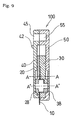
- the cutter cassette 100 includes the cutter case 60, the case holder 70, the holding mechanism, and the extending mechanism.
- the cutter case 60 is constituted by the circular rotary blade 10 and the front and the rear case 20 and 30 which house the rotary blade 10 therein.
- the case holder 70 is constituted by the front and the rear case 40 and 50 which house the cutter case 60 therein.
- the rotary blade 10 is rotatably held along with the shaft 12 in the cutter case 60.
- the cutter case 60 is movably held in the case holder 70 longitudinally along a groove 58.
- the front and the rear case 40 and 50 constituting the case holder 70 are combined by screws on the side opposite to the side from which the rotary blade 10 protrudes so that a portion of the rotary blade 10 can protrudes to the exterior by longitudinally sliding the cutter case 60 therein.
- the screwed portions are denoted by pairs of 47a, 47b, 57a and 57b (refer to Fig. 1).
- the case holder 70 may be combined by a method other than the method using the screws.
- the cutter case 60 can be omitted functionally.
- the shaft 12 (refer to Fig. 1) for supporting the rotary blade 10 is movably housed in the case holder 70.
- the cutter case cutter case 60 which rotatably supports the rotary blade 10 from front and behind, includes cylindrical protrusions 28 and 38 protruding backwardly and forwardly along the central axis of the rotary blade 10.
- the cylindrical protrusions 28 and 38 are positioned such that they are held in grooves 48 and 58 in the case holder 70.
- the cylindrical protrusions 28 and 38 are positioned at the upper ends of the grooves 48 and 58 of the case holder 70 (refer to axis A-A in Fig. 4), the rotary blade 10 is completely housed in the case holder 70.
- the invention includes a holding mechanism for holding the rotary blade 10 in case holder 70 in a completely inserted manner and a release mechanism for the holding mechanism, as shown in the front view of Fig. 4.
- a holding mechanism for holding the rotary blade 10 in case holder 70 in a completely inserted manner
- a release mechanism for the holding mechanism, as shown in the front view of Fig. 4.
- some embodiments need not the release mechanism because an extending mechanism, which will be described later, acts as a release mechanism.
- the cutter cassette 100 includes three protrusions as a holding mechanism and a release mechanism for the rotary blade 10.
- the cutter case 60 has first protrusions 22 protruding outwardly from each end of arms 23 which are cut longitudinally at the front upper part thereof.
- a predetermined pressure is applied to the first protrusions 22, thereby warping them toward hollow portions 34 (refer to Fig. 2) on the inside of the cutter case 60.
- the front case 40 of the case holder 70 includes second protrusions 41 protruding inwardly and third protrusions 42 protruding outwardly.
- the third protrusions 42 are also provided at each end of arms 43 which are cut longitudinally in the front case 40 (refer to Fig. 1). A predetermined pressure is applied to the third protrusions 42, thereby warping them toward the inside of the case holder 70.
- the first protrusions 22 and the second protrusions 41 constitute a holding mechanism and the first protrusions 22 and the third protrusions 42 constitute a release mechanism.
- the first protrusion 22 is disposed right above the second protrusion 41 and the third protrusion 42 is disposed immediately in front of and adjacent to the first protrusion 22 in a state in which the rotary blade 10 is completely housed in the cutter case 60 (refer to Fig. 6).
- the first protrusions 22 and the second protrusions 41 are engaged, so that the cutter case 60 is positioned in the case holder 70 so that the rotary blade 10 is held so as not to protrude outwardly (refer to Fig. 6).
- the bottom of the first protrusion 22 and the upper surface of the second protrusion 41 may be subjected to surface treatment necessary to hold the rotary blade 10 by engaging with each other. For example, it is possible to engage them more securely by increasing friction resistance of the engaging surfaces or by finishing in necessary shape.
- the arms 23 and 43 which support the first protrusion 22 and the third protrusion 42, respectively may be cut in the direction other than the longitudinal direction and also the outline may be curved.
- the size, position, and the number of the protrusions can be modified in accordance with the embodiment, and the invention is not bound by the modification.
- the first protrusion 22 is supported by the second protrusion 41 from below. Since the first protrusion 22 is held as described above, the cutter case 60 is thereby positioned within the case holder 70.
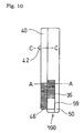
- the layout thereof is shown in the front view of Fig. 4.
- the center point of the rotary blade 10 within the case holder 70 is on the intersection of the lateral axis A-A and the longitudinal axis B-B.
- the third protrusion 42 is disposed adjacent to the first protrusion 22 in the case holder 70, the first protrusion 22 and the third protrusion 42 are arranged in series with the lateral axis C-C, as shown in Fig. 6.
- the state of the cutter cassette 100 at that time is defined as an inoperative state in the first embodiment of the invention.
- each of the first protrusions 22 and the third protrusions 42 have long arms 23 and 43 along the longitudinal direction of the cutter case 60 and the case holder 70, respectively.
- Such arms 23 and 43 are warped backwardly by the pressure from the front (refer to Fig. 7) and project and house the first protrusion 22 and the third protrusion 42 into the hollow portion 34 (refer to Fig. 2) and a hollow portion 44 (refer to Fig. 6), respectively.
- a predetermined force F is applied onto the third protrusion 42
- the arm 43 warps backwardly, and the third protrusion 42 then pushes the first protrusion 22 supported by the second protrusion 41 backwardly.
- the first protrusion 22 warps backwardly and projects into the hollow portion 34, the first protrusion 22 is disengaged from the second protrusion 41, so that the cutter case 60 loses its support and becomes movable downward in the case holder 70 (refer to Fig. 7).
- the center point of the rotary blade 10 which lost the support can come down to the axis A'-A'.
- This position corresponds to a position at which the cylindrical protrusions 28 and 38 formed in the cutter case 60 come down to the lower end of the grooves 48 and 58 formed in the case holder 70. Therefore, only a part of the rotary blade 10, which is journaled in the cutter case 60, protrudes from the gap at the bottom of the case holder 70.
- the state of the cutter cassette 100 at that time is defined as an operative state in the first embodiment of the invention. In this case, only a part of the rotary blade 10 protrudes and the whole rotary blade 10 is not exposed.
- the relative position of the rotary blade 10 in the cutter cassette 100 at that time is shown in the front view of Fig. 5.
- the engagement of the front case 40 and the rear case 50 of the case holder 70 is offset at the protruding side of the rotary blade 10.
- the rear case 50 is slightly protruded downwardly with respect to the front case 40 so that the rotary blade 10 can rotate stably.
- the rear case 30 is slightly protruded downwardly with respect to the front case 20.
- hollow portions 45 and 55 are formed at the upper part of the case holder 70, and are used to hold the cutter cassette 100 in an operative state in position.
- the invention includes the extending mechanism for protruding the rotary blade 10 from within the case holder 70.
- the extending mechanism for protruding the rotary blade 10 from within the case holder 70.
- the extending mechanism shifts the cutter case 60 to an operative state in which it is protruded from the case holder 70.
- the extending mechanism is configured in order to ensure a swift sliding movement of the cutter case 60 in the longitudinal direction of the case holder 70.
- the extending mechanism is a rack mechanism, and engages with a gear mechanism of a cutting device, thereby increasing the amount of translatory motion of the inner cutter case 60 relative to that of the case holder 70, thereby protruding the rotary blade 10.
- the rotary blade 10 is brought in and out only by a unidirectional pushing operation, and the balance between the positioning operations of an inoperative state and an operative state of the rotary blade 10 is maintained by synchronizing the left and the right rack pair.
- Other various mechanisms such as a multistage gear mechanism, a link mechanism, a lever mechanism, and a cam mechanism can be adopted as an extending mechanism according to the invention using, for example, an actuating rod.
- the case holder 70 includes a first rack pair 46 which is bilaterally symmetrical at both sides, and the cutter case 60 includes a second rack pair 36 which is bilaterally symmetrical at both sides, respectively, as an extending mechanism.
- rack pairs 46 and 36 are configured to engage with multistage gears in the cutting device, more preferably, with double gear pairs 86 and 96, and convert the translatory motion of the racks and the rotary motion of the double gears 86 and 96 to each other.
- the rack pairs 46 and 36 are driven in straight lines, so that the gears 86 and 96 are rotated in the same direction.
- the rack pairs 36 and 46 provided at opposite sides of the cutter case 60 and the case holder 70, respectively, are arranged longitudinally in parallel with each other so that part thereof overlaps with each other.
- This is for the purpose of arranging the corresponding multistage gears, preferably, the double gears 86 and 96, for driving the rack pairs 36 and 46 on the same axis, respectively, on the left and right sides of the cutter case 60 and the case holder 70.
- the second rack pair 36 of the cutter case 60 is formed to the center of the rotary blade 10 as compared with the first rack pair 46 of the case holder 70.
- the number of the tooth of gears 96 is larger than that of the gear 86 in the same module.
- the ratio of the number of the tooth of the gear 86 and the gear 96 is substantially 2.
- the ratio may not be limited to 2.0 in the strict sense but is selected from the range larger than 1.
- the rack pairs 36 and 46 are arranged in bilaterally symmetric relation to uniformly scatter the forces necessary for operation left and right.
- the gear pair 86 which engages with the first rack pair 46 of the case holder 70 may be engaged with a third rack pair 76 of the cutting device using the cutter cassette 100 according to the invention.
- the third rack pair 76 is disposed on a holder 71 which surrounds the cutter cassette 100.
- the holder 71 preferably includes a port through which the cutter cassette 100 slides, as shown in Fig. 13. Assuming that the traveling distance of the first rack pair 46 mounted to the case holder 70 is L1, the third rack pair 76 travels the same distance L1 in the opposite direction.
- the traveling distance L2 of the second rack pair 36 for directly moving the rotary blade 10 is in the same direction as that of the case holder 70 and larger than L1, preferably, substantially twice as large as L1.
- the rotary blade 10 can be brought in and out only by a pushing operation from the above at any time.
- the gear pairs 86 and 96 which engage with the rack pairs 46 and 36 are rotated in the same direction and also the downward-traveling distance of the cutter case 60 therein is increased as compared with that of the case holder 70, so that a part of the rotary blade 10 is protruded outwardly to become an operative state.
- the third rack pair 76 on the holder 71 which engages with the gear pair 86, is moved upwardly in a direction opposite from the cutter cassette 100.
- a shaft 90 is fixed in position.
- the operative state of the cutter cassette 100 can be returned to an inoperative state.
- the gear pair 86 is rotated backwardly in correspondence to the downward movement of the third rack pair 76, and the corresponding shaft 90 is rotated backwardly, so that the gear pair 96 is also rotated backwardly to thereby move the rack pairs 46 and 36 which engage therewith, respectively, upwards and to return the cutter cassette 100 to an inoperative state while housing the rotary blade 10 therein.
- the second rack pair 36 travels a distance longer than that of the first rack pair 46 in the same way as when it is protruded. In this manner, only by the pushing operation from the above, the inoperative state and the operative state of the cutter cassette 100 can be freely selected at any time.
- the cutting blade 10 may be extended by using only one rack pair.
- the rack pair 36 is disposed only at the cutter case 60, and the case holder 70 is provided with only openings 59.
- the rotary blade 10 is protruded by using an external gear mechanism. In this case, the extending operation of the rotary blade 10 and the pushing operation of the cutter cassette 100 are not always synchronized with each other.
- the rotary blade 10 is supported by the shaft 12 coaxial with the central axis thereof using a hexagonal bearing 14.
- the rotary blade 10 has a hexagonal supporting hole 13 (refer to Fig. 2) formed at the center thereof and is engaged with and supported by the bearing 14.
- the shaft 12 is formed in a cylindrical shape at opposite ends thereof and is smoothly and freely pivoted in the front cylindrical protrusion 28 and the rear cylindrical protrusion 38 (refer to Fig. 6).
- the shaft 12 is formed in a hexagonal shape at a position to secure the rotary blade 10, so that it is freely pivoted along with the rotary blade 10 via the supporting hole 13 (refer to Fig. 2).
- the shaft 12 may be omitted.
- the cutter case 60 is constituted by the two mating cases 20 and 30 fastened by screws while sandwiching the rotary blade 10 from the back and the front.
- the screwed portions are indicated by the reference numerals 27 and 37 (refer to Fig. 11).
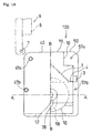
- the rear elevation of the cutter case 60 is shown in Fig. 12 and the front and the rear cylindrical protrusion 28 and 38 are shown with the cross line of the plane A-A and the plane B-B as the center.
- the shape of the cylindrical protrusions 28 and 38 may not be strictly limited to be cylindrical.
- the case holder 70 has the openings 59 (refer to Figs. 1 and 10) at portions of opposite sides of the case holder 70 in order to engage the second rack pair 36 at opposite sides of the cutter case 60 with the gear pair 96 of the cutting device, so that the rack pairs 36 and 46 can directly engage with the gear pairs 96 and 98 of the cutting device. While the invention is office equipment, the two rack pairs constituting the cutter cassette are exposed to the exterior, thereby facilitating manual sliding work and the like and improving maintaining ability.
- the rack pairs 36 and 46 can be separately and removably attached to the cutter cassette 100 according to the invention.
- a structural example including three protrusions as a holding mechanism and a release mechanism is shown.
- a spring, a magnet, implanted hair, or the like is shown as a holding mechanism.
- Such configurations do not particularly need a release mechanism.
- a structural example including a rack and a gear as an extending mechanism is shown.
- a protrusion may be provided at an outside surface of the cutter cassette 100 in place of the actuating rod and is engaged with a cam groove formed in an external mechanism, thereby extending the cutting blade 10 of the cutter cassette 100 according to the invention. Furthermore, it is also possible to extend the cutting blade 10 manually without the external mechanism.
- the cutter cassette 100 is similarly constituted by a cutter case, a case holder, a holding mechanism, a release mechanism, and an extending mechanism.
- portions corresponding to the holding mechanism and the release mechanism are modified as compared with the first embodiment.
- the three protrusions 22, 41, and 42 according to the first embodiment are modified to a single elastic body 1 (refer to Fig. 14). Accordingly, the configuration is modified to a more simplified shape.
- the elastic body 1 is a spring having predetermined elasticity.
- the cutter cassette 100 has the spring 1 mounted therein as a holding mechanism and a release mechanism.
- the spring 1 is disposed in a substantially inverted V shape, one end (refer to numeral 2 in Fig. 16) of which is attached to the cutter case 60 side and the other end (refer to numeral 4 in Fig. 14) is attached to the case holder 70 side, thereby applying elasticity between them.
- the elasticity of the spring normally causes the cutter case 60 to be pulled into the case holder 70.
- the state of the cutter cassette 100 at that time is defined as an inoperative state in the second embodiment.
- the front view of Fig. 14 corresponds to a side view of Fig. 16.
- the axis A-A corresponds to the axis A-A in Fig. 4 which shows an inoperative state of the cutter cassette 100 in the first embodiment.
- an end 4 of the spring 1 is disposed in the horizontal direction parallel to the axis A-A, and a hollow 3 is formed in the case holder 70 and adjacent to the end 4 of the spring 1.
- the second embodiment of the invention also includes a function of extending a portion of the rotary blade 10 outwardly from the case holder 70 in a manner similar to the above-described first embodiment.
- a description of a method for extending the rotary blade 10 using the extending mechanism constituted by the racks and the gears will be omitted in order to avoid overlaps of description.
- the spring 1 has elasticity sufficient to hold the cutter case 60 in the case holder 70 in a completely inserted state, as described above.
- a force larger than designated elasticity provided for the spring 1 is applied to the cutter case 60 from the exterior, as shown in Fig. 15, the cutter case 60 slides downward in the case holder 70 to extend a portion of the rotary blade 10 outwardly from the case holder 70.
- the end portion 2 of the spring 1 which is secured to the cutter case 60 side, comes down, so that the spring 1 is compressed vertically in accordance with the movement of the cutter case 60.
- the end 4 of the spring 1 escapes into the hollow 3 of the adjacent case holder 70.
- the end 4 is inclined upwardly from a horizontal position parallel to the initial axis A-A.
- the spring 1 applies designated elasticity between the cutter case 60 and the case holder 70 to bring the cutter case 60 into the case holder 70 again.
- the state of the cutter cassette 100 at that time is defined as an operative state in the second embodiment.
- a front view of Fig. 15 corresponds to a side view of Fig. 17.
- the axis A'-A' in Fig. 15, which shows an operative state of the cutter cassette 100 in the second embodiment, corresponds to the axis A'-A' in Fig. 5, which shows an operative state of the cutter cassette 100 in the first embodiment.
- a holding mechanism of the cutter cassette 100 is constituted by using elasticity of the spring 1.
- a release mechanism for releasing the holding mechanism is constituted by using the elasticity of the spring 1.
- the position, number, and shape of the spring 1 in the cutter cassette 100 can be modified. Specifically, it is sufficient for the spring 1 to satisfy the holding mechanism and the release mechanism.
- Magnets, implanted hair, or the like may be used as the holding mechanism in place of the plate spring. Specifically, magnets or implanted hair are provided to face each other at the outer surface of the cutter case 60 and the inner surface of the case holder 70 to hold the cutting blade 10 in the cutter cassette 100 in an inoperative state with the force of attraction or friction so that it does not protrude therefrom.
- a release mechanism for the holding mechanism is used in combination with an extending mechanism using an external driving mechanism.
- the cutter case 60 is pushed out from the case holder 70 by applying an external force from the above, thereby shifting the cutting blade 10 to an operative state. Accordingly, the cutter case 60 and the case holder 70 do not include racks and are constituted in a simpler way. However, the external force is transmitted via the actuating rod 9.
- the case holder 70 has an opening 18 (refer to Fig. 19) formed therein, through which an external force is directly applied using the actuating rod 9 to the cutter case 60 in the case holder 70.
- the cutter case 60 has a protrusion 19 for receiving an external force from the exterior. The protrusion 19 slides along the opening 18 in the case holder 70, thereby sliding the cutter case 60 integrated with the protrusion 19 in the same direction in the case holder 70.
- the protrusion 19 and the opening 18 are arranged in parallel with each other, thereby allowing the external force to be promptly applied onto the protrusion 19 via the actuating rod 9 (refer to Figs. 18 and 20).
- the actuating rod 9 may not be pivoted in the vicinity of the portion 7 in the strict sense. Furthermore, the actuating rod 9 may not be pivoted but may be slid vertically in parallel with the traveling direction of the cutter case 60 to bring the protrusions 8 and 19 into contact with each other, thereby pushing the protrusion 19 into the case holder 70 using the protrusion 8.
- the actuating rod 9 is returned to an initial state, and the protrusion 8 and the protrusion 19 are thereby disengaged from each other.
- the spring 1 provided in the cutter cassette 100 is returned to an initial state using designated elasticity to thereby terminate the extending operation.
- the principle of the terminating operation of the operative state is different from that of the holding mechanism and the release mechanism according to the first embodiment.
- this embodiment adopts the same mechanism as that of the first embodiment as a holding mechanism and a release mechanism. Therefore, a description of the holding mechanism and the release mechanism will be omitted here.
- an extending mechanism is modified in this embodiment. Specifically, actuating rods 105 are disposed adjacent to each other on opposite outer sides of the cutter cassette 100 as an extending mechanism. Only the modified extending mechanism will be described hereinbelow in order to avoid overlaps of description.
- the actuating rods 105 are preferably disposed in bilaterally symmetric relation to each other on opposite sides of the cutter cassette 100. Specifically, each of the actuating rods 105 is curved perpendicularly about a portion 101 and pivotal about the portion 101.
- the actuating rod 105 has an actuating portion 102 for extension at an end thereof and an operating portion 104 at the other end thereof. In operation, the actuating rod 105 is pivoted about the portion 101, so that the actuating portion 102 is engaged with the cutter case 60 in the case holder 70.
- the case holder 70 has the openings 59 formed on opposite sides thereof so that the cutter case 60 in the case holder 70 faces the exterior directly. Since the cutter case 60 also has bilaterally symmetrical grooves 26 for engaging with the actuating portions 102 at positions to face the exterior from the opposite openings 59.
- a front view of Fig. 22 corresponds to a plan view of Fig. 23.
- the actuating portion 102 may be chamfered at an end 102' and the groove 26 may be chamfered at an end 26' so that the actuating portion 102 comes into the groove 26 smoothly (refer to Figs. 22 and 23).
- a protrusion 103 may be formed in the cutting device 500. More specifically, the operating portion 104 of the actuating rod 105, which is opposite to the actuating portion 102, is brought into engagement with the protrusion 103, thereby fixing the cutter cassette 100 in an operative state. A description regarding the cutting device 500 will be described later.
- this embodiment adopts the same mechanism as that of the first embodiment as a holding mechanism and a release mechanism. Therefore, a description regarding the holding mechanism and the release mechanism will be omitted.
- an extending mechanism is modified in this embodiment. Specifically, actuating rods are disposed on opposite sides of the cutter cassette 100 as an extending mechanism. Only the modified extending mechanism will be described hereinbelow to avoid overlaps of description.
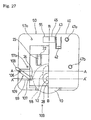
- actuating rods 109 are disposed on opposite sides of the cutter cassette 100, as shown in Fig. 25.
- the straight actuating rods 109 are each disposed pivotally about the portion 106.
- Each of the actuating rods 109 has an actuating portion 107 for extending operation at an end thereof.
- the actuating rod 109 is pivoted about the portion 106, so that the actuating portion 107 is engaged with the groove 26 of the cutter case 60 in the case holder 70.
- the case holder 70 has the openings 59 formed on opposite sides thereof so that the cutter case 60 in the case holder 70 faces the exterior directly. Since the cutter case 60 has bilaterally symmetrical grooves 26 for engaging with the actuating portions 107 at positions to face the exterior through the opposite openings 59.
- a front view of Fig. 25 corresponds to a plan view of Fig. 26.
- the actuating portions 107 are chamfered in order that they come into the grooves 26 smoothly (refer to Fig. 25).
- Fig. 27 shows the cutter cassette 100 using the actuating rods 109 in an operative state.
- each actuating rod 109 is pivoted about the portion 106, thereby engaging the actuating portion 107 into the groove 26 on the side of the cutter case 60 through the opening 59.
- the cutter case 60 is moved downward in the case holder 70 in synchronization with the engaging action.
- an operating portion 108 is formed at an opposite end of the actuating rod 109 from the actuating portion 107 (refer to Fig. 27). More specifically, the actuating portion 107 is engaged with the groove 26 by vertically moving the operating portion 108. As shown in Fig. 13, the holder 71 is formed in the cutting device, with which the operating portion 108 is engaged, so that the vertical movement of the operating portion 108 may be synchronized with the movement of the holder 71.
- the cutter cassette 100 has a cam groove formed in the cutting device. More specifically, the cutter cassette 100 has a protrusion formed on the exterior thereof and connected with the cutting blade 10, and the cutting device has a cam groove formed therein for guiding the protrusion, thereby extending the cutting blade 10 outwardly in synchronization with the pushing motion of the cutter cassette 100 into the cutting device (not shown).
- a driving mechanism used for the cutter cassette 100 which has gears in place of the second rack pair 36 (refer to Fig. 1 or 3) disposed at the cutter case 60 and has a rack mechanism in place of the gear mechanism 96 (refer to Fig. 13) disposed in the cutting device, which are engaged with each other.
- the gears integrated with the cutter case 60 are driven by the racks provided in the cutting device and the traveling distance of the cutter case 60 is increased as compared with that of the case holder 70, thereby extending the cutting blade 10 outwardly (not shown).
- the cutting device has openings facing the openings of the cutter cassette 100, through which the cutter case 60 in the cutter cassette 100 is handled, thereby extending the cutting blade 10 outwardly (not shown).
- a cutting device having a rail and a slider on a base, a hand-operated portable cutter of compact size, and the like for cutting using the cutter cassette 100. While the cutting device will be specifically described hereinafter, the configuration of the cutter cassette 100 according to the invention similarly applies to the hand-operated cutter.
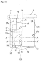
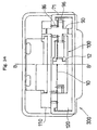
- Fig. 28 is a front view of the cutting device 500 according to the embodiments of the invention.
- the rotary blade 10 is used as a cutting blade 10 such that it is protruded along the central axis B-B of a slider 300.
- the slider 300, to which the cutter cassette is mounted moves rectilinearly on the axis G-G of a rail 200.
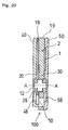
- Fig. 29 is a plan view of the slider 300.
- the slider 300 has a mounting portion 130 thereon, on which the cutter cassette 100 is detachably mounted. Since the mounting portion 130 is opened at the top of the top cover 140, the cutter cassette 100 mounted in the slider 300 can be discriminated irrespective of whether it is in an operative state or in an inoperative state. With such a configuration, when the cutting device is used as office equipment, the types of various cutting blades such as a waveform blade and a perforating blade can be discriminated immediately. It is possible to give color for discrimination or attach a discriminating label or the like onto the cutter cassette 100 to be used.
- the mounting portion 130 is formed as an opening surrounded from every direction as viewed from the above, as shown in Fig. 29, it may be formed to open one of all sides as viewed from the above.
- the mounting portion 130 may be formed in a dovetail shape, as shown in Fig. 38A; alternatively, it may be formed to open to one side, as shown in Fig. 38B; and it may also be formed in a shape shown in Fig. 38C.
- the shape of the mounting portion 130 may be modified while maintaining the function for mounting the cutter cassette 100.
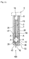
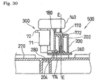
- Figs. 30 and 31 are side views of the slider 300 according to an embodiment.
- an engaging portion 172 of the sliding portion 170 is slidably disposed in a groove 202 extending longitudinally at the center of the rail 200.
- the groove 202 and the engaging portion 172 are arranged in a row on the axis E-E.
- the sliding portion 174 of the slider 300 is engaged with a protrusion 204 at the lower part of the rail 200, and the slider 300 is thereby positioned vertically.
- the slider 300 may be mounted on the rail 200 with other mechanisms.
- a cutter mat 280 is provided at a designated place on the base 270, thereby preventing direct contact of the cutting blade 10 with the base 270.
- a spring member 180 is placed between the top cover 140 and the sliding portion 170 to push the top cover 140 downward from the above when cutting, thereby moving the slider 300 downward to bring the rotary blade 10 into contact with paper.
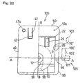
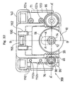
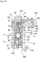
- the slider 300 of the cutting device 500 is configured assuming the use of the cutter cassette 100. Referring to Figs. 32 to 38, the inner structure of the slider 300 to which the cutter cassette 100 is mounted therein for use will be described.
- Fig. 32 is a front view of the slider 300 according to the first embodiment of the invention. However, the drawing is divided left and right, and integral parts including the rotary blade 10 are shown in perspective for the purpose of a clear understanding.
- a housing portion of the slider 300 for the cutter cassette 100 includes gears, preferably, a gear mechanism including a double gear at positions facing opposite sides of the cutter cassette 100.
- the corresponding cutting device 500 also has a lever mechanism in place of the gear mechanism in the slider 300. More specifically, a mechanism using the actuating rod, shown in Figs. 18 to 24, may be provided.
- a cam groove or the like for extending the cutting blade 10 housed in the cutter cassette 100 may be provided within the scope of the claims according to the invention.
- the case holder 70 constituting the cutter cassette 100 includes the rack pair 46 at opposite sides thereof, thereby engaging with the double gear pair 86
- the cutter case 60 holding the rotary blade 10 includes the rack pair 36 at opposite sides thereof, thereby engaging with the double gear pair 96 (refer to Fig. 13).
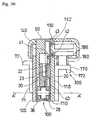
- the gear pairs 86 and 96 constituting the double gear, and the shaft 90 are positioned so as to be sandwiched by cutter-cassette supporting portions 110 and 120 from the front and the back (refer to Fig. 34).
- the cutter cassette supporting portions 110 and 120 are joined by screws at portions 112a, 112b, 122a, and 122b.
- the top cover 140 is disposed to cover the cutter-cassette supporting portions 110 and 120, and the holder 71 for taking out the cutter cassette 100 is disposed under the top cover 140 such that it is slidable in the vertical direction.
- the holder 71 does not move upwardly over the top cover 140 in general.
- the holder 71 is engaged with the double gear pair 86 to rotate it, thereby rotating the double gear pair 96 held on the same shaft 90 in the same direction.
- the gear pairs 86 and 96 can be arranged adjacent to each other on the shaft 90, as shown in Fig. 34.
- the gears may be arranged in reverse order in front and rear. Also, such gears may be formed integrally with a corresponding shaft, may be attached by key grooves, and may be attached by an involute spline or the like. Furthermore, such gears may constitute a gear train along with other gears.
- the cutter cassette 100 in an inoperative state, into which the rotary blade 10 is inserted, is inserted through the mounting portion 130 (refer to Fig. 29) formed between the front and rear cutter-cassette supporting portions 110 and 120.
- the cutter-cassette supporting portion 110 includes protrusions 162 for pushing the third protrusions 42 (refer to Fig. 1) of the cutter cassette 100 inwardly at portions facing the cutter cassette 100.
- each third protrusion 42 protruding to the exterior of the case holder 70 is first guided on an inclined plane 161 which is gradually inclined inwardly.
- the third protrusion 42 is pushed into the case holder 70 by a protrusion 162 in the slider 300 and is held therein.
- the first protrusion 22 of the cutter case 60 and the second protrusion 41 of the case holder 70 are disengaged from each other by the pressure from the third protrusions 42 (refer to Fig. 35).
- the third protrusion 42 has been pushed inwardly by the protrusion 162 in the slider 300, it is guided on a steep inclined plane 163 and returns to the initial state.
- the first protrusion 22 comes down below the second protrusion 41, thereby shifting the rotary blade 10 into an operative state.
- the rotary blade 10 can be synchronously protruded outwardly from the cutter cassette 100. Therefore, according to the invention, the cutting blade is housed completely in the cutter cassette, thereby providing a high degree of safety, and a blade interchanging work is performed only by pushing operation from the above, thereby improving the operability dramatically. Accordingly, although the cutting blade is normally interchanged by troublesome work while a portion of the blade is exposed in the conventional art, the invention effectively solves the above problems of poor safety and troublesome operability.
- the operation of pushing the cutter cassette into the cutting device and the operation of extending the cutting blade may not be connected with each other.
- an extending mechanism is not provided on the sides of the case holder 70, but only on the sides of the inner cutter case 60. Therefore, it is also possible that the cutter cassette 100 be mounted in the cutting device at the first stage, and the extending mechanism of the cutter case 60 be operated using the driving mechanism provided for the cutting device, thereby extending the cutting blade 10.
- the pressure of the protrusion 162 in the slider 300, shown in Fig. 35, to the cutter cassette 100 satisfies the force F, shown in Fig. 7.
- the holding mechanism and the release mechanism of the cutter cassette 100 are formed of an elastic body such as a spring 1 (refer to Fig. 14) or the like, only the extending mechanism is used to shift the cutting blade 10 into an operative state in place of the pressure of the protrusion 162 in the slider 300 to the cutter cassette 100.
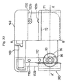
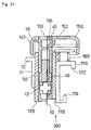
- the slider 300 includes a cutter cassette stopper 150 at the top of the top cover 140 and adjacent to the mounting portion 130.
- the cutter cassette stopper 150 is slidable toward the mounting portion 130 and includes a protrusion 155 on the side facing the mounting portion 130.
- the cutter cassette stopper 150 is a predetermined distance away from the mounting portion 130 before pushing the cutter cassette 100 into the mounting portion 130, thereby allowing the cutter cassette 100 to be smoothly inserted in the mounting portion 130 without any troubles.
- the cutter cassette stopper 150 is slid toward the mounting portion 130, thereby inserting the protrusion 155 into the hollows 45 and 55 at the front upper part of the cutter cassette 100, as shown in Fig. 37. Accordingly, the cutter cassette 100 is held in an operative state while being positioned, thereby allowing cutting work to be performed with stability.
- the cutter cassette stopper 150 according to the embodiment of the invention has a plurality of shallow grooves 152 for sliding formed at the top thereof, thereby improving sliding operability by hand. The operability can be improved using alternative suitable members.
- the cutter cassette stopper 150 may be operated by hand in accordance with the state of mount/demount of the cutter cassette 100, or may be operated automatically.
- the cutter cassette stopper 150 may be pivotal. Particularly, when the cutter cassette 100 is operated using the actuating rod 9 of the cutting device, as shown in Fig. 18, the actuating rod 9 may be used in place of the cutter cassette stopper 150.
- a shift from an operative state to an inoperative state of the cutter cassette 100 is performed by the reverse operation from the above operation.
- rack levers 72 are provided on the back of the holder 71 having the third rack pair 76 on the left and right.
- the rack levers 72 protrude outwardly and perpendicularly from the back of the holder 71, thereby improving the operability. It is possible to modify the rack lever 72 into a shape which is easily gripped to enhance the usability.
- the rack lever 72 is moved upwardly as the cutter cassette 100 is pushed.
- the base 270 may include a cutter-cassette mounting portion (not shown) for housing a plurality of the cutter cassettes 100. This is for the purpose of promptly ejecting the cutter cassettes 100 having a plurality of the cutting blades 10 to be used for the cutting device 500 for interchanging.
- the cutter-cassette mounting portion can be configured to be removable from the base 270.
- the cutting blade can be promptly extended from the cutter cassette when used, that is, in an operative state.
- the cutting blade can be securely housed and held in the cutter cassette when not used, that is, in an inoperative state.
- the cutting blade can be housed in the cutter cassette in an inoperative state by using the holding mechanism, and the cutting blade in the cutter cassette can easily be extended in an operative state using the release mechanism and the extending mechanism, thereby improving safety and operability.
- the cutting blade can easily be held in the case holder by using the cutter case, and greater flexibility of positioning operation in the case holder and also various functions can be provided by providing various functions on the outer surface of the cutter case.
- the cutting blade in an inoperative state, can easily be housed in the cutter cassette by using the holding mechanism and, in an operative state, the cutting blade in the cutter cassette can be movably projected with greater flexibility of operation by using the release mechanism and the extending mechanism, thereby providing a cutter cassette having improved safety and operability.
- the holding mechanism can be configured simply by using the two protrusions.
- the release mechanism can be configured simply by using the three protrusions.
- the holding mechanism can be configured simply by using the spring.
- the holding mechanism can be configured simply by using the magnets.
- the holding mechanism can be configured simply by using the implanted hair.
- the extending mechanism of the cutter cassette according to the invention can extend the cutting blade by using the driving mechanism mounted to a cutting device. Furthermore, the cutting blade can be extended at the same time the cutter cassette according to the invention is mounted to the cutting device.
- the extending mechanism can be operated promptly by using the driving mechanism through the opening.
- the cutting blade can be extended by operating the extending mechanism by using the cutter cassette in combination with the driving mechanism using a gear mechanism of the cutting device.
- the extending mechanism is operated by using the cutter cassette in combination with the driving mechanism using the gear mechanism of the cutting device to thereby increase the traveling distance of the cutter case as compared with that of the case holder, thereby extending the cutting blade.
- the cutter cassette when the cutter cassette is inserted into the cutting device, the cutter cassette is detachably housed in the cutting device, and can be promptly discriminated via the cutter-cassette mounting portion. Moreover, the cutting blade in the cutter cassette can be shifted to an operative state by using the driving mechanism when the cutter cassette is pushed in, thereby setting the cutting device into an operative state.
- a multistage gear is used as a driving mechanism, and the traveling distance of the inner cutter case is increased as compared with that of the case holder, thereby allowing the cutting blade to project.
- a multistage gear is used as a driving mechanism to extend the cutter case in the case holder after the cutter cassette has been mounted in the cutting device, thereby allowing the cutting blade to project.
- the cutter case is extended in the case holder after the cutter cassette has been mounted in the cutting device, thereby allowing the cutting blade to project.
- an engaging portion for positioning the cassette is unnecessary.
- the cutting blade can be shifted to an operative state in synchronization with the operation of pushing the cutter cassette into the cutting device.
- the cutting blade can be shifted to an operative state in synchronization with the operation of pushing the cutter cassette into the cutting device.
- a complex driving mechanism is omitted, thereby providing a simple and economical cutting device.
Applications Claiming Priority (2)
| Application Number | Priority Date | Filing Date | Title |
|---|---|---|---|
| JP2001040560A JP3619993B2 (ja) | 2001-02-16 | 2001-02-16 | カッターカセット及び裁断具 |
| JP2001040560 | 2001-02-16 |
Publications (3)
| Publication Number | Publication Date |
|---|---|
| EP1232841A2 EP1232841A2 (en) | 2002-08-21 |
| EP1232841A3 EP1232841A3 (en) | 2004-11-10 |
| EP1232841B1 true EP1232841B1 (en) | 2006-05-24 |
Family
ID=18903145
Family Applications (1)
| Application Number | Title | Priority Date | Filing Date |
|---|---|---|---|
| EP02003174A Expired - Lifetime EP1232841B1 (en) | 2001-02-16 | 2002-02-15 | Cutter cassette and cutting device using the same |
Country Status (5)
| Country | Link |
|---|---|
| US (1) | US6782785B2 (zh) |
| EP (1) | EP1232841B1 (zh) |
| JP (1) | JP3619993B2 (zh) |
| CN (1) | CN1280073C (zh) |
| DE (1) | DE60211576T2 (zh) |
Families Citing this family (25)
| Publication number | Priority date | Publication date | Assignee | Title |
|---|---|---|---|---|
| TW200420397A (en) * | 2003-01-24 | 2004-10-16 | Fiskars Brands Inc | Craft trimmer assembly |
| US20060117925A9 (en) * | 2003-07-24 | 2006-06-08 | Boris Volfson | Rotary trimmer with switchable blades |
| US7415915B2 (en) * | 2005-04-05 | 2008-08-26 | Elmer's Products, Inc. | Cutting system having an interchangeable rotary blade cartridge |
| US20070028463A1 (en) * | 2005-08-02 | 2007-02-08 | Chan Stephen K K | Paper cutter |
| US7503247B2 (en) * | 2005-09-19 | 2009-03-17 | Parkinson Technologies, Inc. | Dual inline slitter |
| DE202006002004U1 (de) * | 2006-02-07 | 2007-06-21 | Weidmüller Interface GmbH & Co. KG | Abmantelwerkzeug |
| DE202006002320U1 (de) * | 2006-02-13 | 2007-03-29 | Monolith GmbH Bürosysteme | Schneidgerät zum Schneiden von Blattgut |
| US20090013844A1 (en) | 2007-04-10 | 2009-01-15 | Acco Brands Usa Llc | Sheet trimmer |
| US20100037787A1 (en) * | 2008-08-13 | 2010-02-18 | Annbjorg Eide | Rotary food cutter with removable blade assembly |
| JP5537542B2 (ja) | 2009-03-16 | 2014-07-02 | カール事務器株式会社 | 裁断具 |
| CN101878956B (zh) * | 2010-06-21 | 2012-10-24 | 季庆 | 移动式小型烟支、滤棒分析切割装置 |
| DE102010055487A1 (de) * | 2010-12-22 | 2012-06-28 | Dahle Bürotechnik Gmbh | Rollenschneider |
| JP5787209B2 (ja) * | 2011-04-12 | 2015-09-30 | 和博 川崎 | 紙切カッター |
| CN105710907B (zh) * | 2015-12-31 | 2018-11-13 | 宁波市恺丰文具礼品有限公司 | 一种流苏制作器 |
| KR20180080641A (ko) * | 2017-01-04 | 2018-07-12 | 임지오 | 절단장치 |
| EP4252983A3 (en) * | 2017-05-01 | 2023-11-15 | Avery Dennison Retail Information Services LLC | Method for reducing label waste using a cutting apparatus |
| CN108858417A (zh) * | 2017-05-12 | 2018-11-23 | 台湾欧西玛股份有限公司 | 刀盘换刀结构及其方法 |
| EP3626417A1 (en) * | 2017-05-15 | 2020-03-25 | Erqus&Quercia, S.L. | Food slicer |
| CN107020661B (zh) * | 2017-05-31 | 2019-02-15 | 柳州英飞科技有限公司 | 一种桥梁维护设备 |
| US11565539B2 (en) | 2018-04-30 | 2023-01-31 | Hewlett-Packard Development Company, L.P. | Forward and backward rotation of printer cutters |
| CN108994886B (zh) * | 2018-06-28 | 2020-04-10 | 广西大学行健文理学院 | 一种园林用花卉培养盆切割装置 |
| US10710265B2 (en) * | 2019-01-21 | 2020-07-14 | Heather M. Snow | Blade saver |
| EP3936288A1 (de) * | 2020-07-10 | 2022-01-12 | Bizerba SE & Co. KG | Abschneider für selbstklebende trägerlose endlosband-etiketten |
| DE102021115309A1 (de) | 2021-06-14 | 2022-12-15 | Multivac Sepp Haggenmüller Se & Co. Kg | Aufschneide-Maschine mit Messer-Montagevorrichtung |
| CN115383810B (zh) * | 2022-10-25 | 2023-02-17 | 三丰盈新材料(江苏)有限公司 | 一种耐高温胶带生产用胶带冲裁装置 |
Family Cites Families (13)
| Publication number | Priority date | Publication date | Assignee | Title |
|---|---|---|---|---|
| US3740848A (en) * | 1971-08-16 | 1973-06-26 | J Lindley | Rotary cutter assembly |
| DE4205798A1 (de) * | 1991-03-01 | 1992-09-03 | Dienes Werke | Laengsschneidemaschine mit schneidkassette |
| US5332001A (en) | 1993-08-02 | 1994-07-26 | J. C. Carter Company, Inc. | Sexless ball valve coupling |
| JP3586748B2 (ja) * | 1993-12-29 | 2004-11-10 | カシオ計算機株式会社 | カッタ装置 |
| JP3125132B2 (ja) * | 1995-10-31 | 2001-01-15 | カール事務器株式会社 | カッター用回転刃のホルダ |
| JP2899242B2 (ja) * | 1995-12-15 | 1999-06-02 | さくら精機株式会社 | ペーパーカッター |
| JPH09323297A (ja) * | 1996-06-06 | 1997-12-16 | Casio Comput Co Ltd | カッタ装置およびカッタカートリッジ |
| US5996459A (en) | 1997-08-29 | 1999-12-07 | Fiskars Inc. | Paper trimmer |
| JP3385456B2 (ja) * | 1998-05-29 | 2003-03-10 | カール事務器株式会社 | 紙裁断機 |
| JP3951159B2 (ja) | 1998-07-29 | 2007-08-01 | カール事務器株式会社 | カセット装着具 |
| JP2000117697A (ja) * | 1998-10-13 | 2000-04-25 | Carl Manufacturing Co Ltd | 孔明け装置 |
| US6249975B1 (en) * | 1999-12-20 | 2001-06-26 | Hsing Tai Lin | Blade support device for a knife |
| US6438850B2 (en) * | 2000-04-12 | 2002-08-27 | Progressive International Corp. | Roller cutter with retractable and removable cutter wheel |
-
2001
- 2001-02-16 JP JP2001040560A patent/JP3619993B2/ja not_active Expired - Fee Related
-
2002
- 2002-02-13 US US10/073,176 patent/US6782785B2/en not_active Expired - Fee Related
- 2002-02-15 DE DE60211576T patent/DE60211576T2/de not_active Expired - Fee Related
- 2002-02-15 EP EP02003174A patent/EP1232841B1/en not_active Expired - Lifetime
- 2002-02-19 CN CN02105138.0A patent/CN1280073C/zh not_active Expired - Fee Related
Also Published As
| Publication number | Publication date |
|---|---|
| JP3619993B2 (ja) | 2005-02-16 |
| CN1370663A (zh) | 2002-09-25 |
| DE60211576D1 (de) | 2006-06-29 |
| EP1232841A2 (en) | 2002-08-21 |
| JP2002239266A (ja) | 2002-08-27 |
| US20020112586A1 (en) | 2002-08-22 |
| CN1280073C (zh) | 2006-10-18 |
| US6782785B2 (en) | 2004-08-31 |
| DE60211576T2 (de) | 2007-05-10 |
| EP1232841A3 (en) | 2004-11-10 |
Similar Documents
| Publication | Publication Date | Title |
|---|---|---|
| EP1232841B1 (en) | Cutter cassette and cutting device using the same | |
| US7040208B2 (en) | Cutter cassette and cutting device | |
| EP0658133B1 (en) | Razor handle mechanism with convex-concave slidable cartridge support | |
| KR101157913B1 (ko) | 리드 개폐 장치 | |
| JP4347704B2 (ja) | 横側装填式外科手術用牽引具 | |
| US9492931B2 (en) | Utility knife | |
| EP1597029B1 (en) | Shaving implement | |
| TWI248390B (en) | Utility knife | |
| US20150174772A1 (en) | Safety Cutter Apparatus | |
| EP1236530B1 (en) | Blade clamp suitable for reciprocating power tools | |
| US7395603B2 (en) | Reciprocating saw | |
| KR101238324B1 (ko) | 스탬핑 장치 | |
| EP1935267A1 (en) | Shield locking mechanism for helmet | |
| JPH0671574A (ja) | ステプラー | |
| US7409898B2 (en) | Paper cutter | |
| JP2006068940A (ja) | 切断機のキックバック防止装置 | |
| CN111975819A (zh) | 一种美工刀 | |
| US6978102B2 (en) | Ejection apparatus and method | |
| US20060207401A1 (en) | Cutting tool assembly | |
| JP3765397B2 (ja) | 熱転写プリンタ | |
| CN220218572U (zh) | 一种回弹定位两用刀具 | |
| JPH07195297A (ja) | カッタ装置 | |
| CN220451629U (zh) | 锁定装置 | |
| JP2571915Y2 (ja) | 穿孔機 | |
| CN112207861B (zh) | 剪刀 |
Legal Events
| Date | Code | Title | Description |
|---|---|---|---|
| PUAI | Public reference made under article 153(3) epc to a published international application that has entered the european phase |
Free format text: ORIGINAL CODE: 0009012 |
|
| AK | Designated contracting states |
Kind code of ref document: A2 Designated state(s): AT BE CH CY DE DK ES FI FR GB GR IE IT LI LU MC NL PT SE TR |
|
| AX | Request for extension of the european patent |
Free format text: AL;LT;LV;MK;RO;SI |
|
| PUAL | Search report despatched |
Free format text: ORIGINAL CODE: 0009013 |
|
| AK | Designated contracting states |
Kind code of ref document: A3 Designated state(s): AT BE CH CY DE DK ES FI FR GB GR IE IT LI LU MC NL PT SE TR |
|
| AX | Request for extension of the european patent |
Extension state: AL LT LV MK RO SI |
|
| RIC1 | Information provided on ipc code assigned before grant |
Ipc: 7B 26D 7/22 B Ipc: 7B 26D 7/26 A |
|
| 17P | Request for examination filed |
Effective date: 20041229 |
|
| 17Q | First examination report despatched |
Effective date: 20050406 |
|
| AKX | Designation fees paid |
Designated state(s): DE FR GB |
|
| GRAP | Despatch of communication of intention to grant a patent |
Free format text: ORIGINAL CODE: EPIDOSNIGR1 |
|
| RIN1 | Information on inventor provided before grant (corrected) |
Inventor name: SHIMIZU, FUMIO Inventor name: MORI, MAKOTO |
|
| GRAS | Grant fee paid |
Free format text: ORIGINAL CODE: EPIDOSNIGR3 |
|
| GRAA | (expected) grant |
Free format text: ORIGINAL CODE: 0009210 |
|
| AK | Designated contracting states |
Kind code of ref document: B1 Designated state(s): DE FR GB |
|
| REG | Reference to a national code |
Ref country code: GB Ref legal event code: FG4D |
|
| REF | Corresponds to: |
Ref document number: 60211576 Country of ref document: DE Date of ref document: 20060629 Kind code of ref document: P |
|
| ET | Fr: translation filed | ||
| PLBE | No opposition filed within time limit |
Free format text: ORIGINAL CODE: 0009261 |
|
| STAA | Information on the status of an ep patent application or granted ep patent |
Free format text: STATUS: NO OPPOSITION FILED WITHIN TIME LIMIT |
|
| 26N | No opposition filed |
Effective date: 20070227 |
|
| PGFP | Annual fee paid to national office [announced via postgrant information from national office to epo] |
Ref country code: DE Payment date: 20080219 Year of fee payment: 7 |
|
| PGFP | Annual fee paid to national office [announced via postgrant information from national office to epo] |
Ref country code: FR Payment date: 20080214 Year of fee payment: 7 |
|
| REG | Reference to a national code |
Ref country code: FR Ref legal event code: ST Effective date: 20091030 |
|
| PG25 | Lapsed in a contracting state [announced via postgrant information from national office to epo] |
Ref country code: DE Free format text: LAPSE BECAUSE OF NON-PAYMENT OF DUE FEES Effective date: 20090901 |
|
| PG25 | Lapsed in a contracting state [announced via postgrant information from national office to epo] |
Ref country code: FR Free format text: LAPSE BECAUSE OF NON-PAYMENT OF DUE FEES Effective date: 20090302 |
|
| PGFP | Annual fee paid to national office [announced via postgrant information from national office to epo] |
Ref country code: GB Payment date: 20100218 Year of fee payment: 9 |
|
| GBPC | Gb: european patent ceased through non-payment of renewal fee |
Effective date: 20110215 |
|
| PG25 | Lapsed in a contracting state [announced via postgrant information from national office to epo] |
Ref country code: GB Free format text: LAPSE BECAUSE OF NON-PAYMENT OF DUE FEES Effective date: 20110215 |