EP1223236A2 - Vorrichtung zur Herstellung eines Core-Garns - Google Patents
Vorrichtung zur Herstellung eines Core-Garns Download PDFInfo
- Publication number
- EP1223236A2 EP1223236A2 EP01130244A EP01130244A EP1223236A2 EP 1223236 A2 EP1223236 A2 EP 1223236A2 EP 01130244 A EP01130244 A EP 01130244A EP 01130244 A EP01130244 A EP 01130244A EP 1223236 A2 EP1223236 A2 EP 1223236A2
- Authority
- EP
- European Patent Office
- Prior art keywords
- thread
- fiber
- guide
- yarn
- guide channel
- Prior art date
- Legal status (The legal status is an assumption and is not a legal conclusion. Google has not performed a legal analysis and makes no representation as to the accuracy of the status listed.)
- Granted
Links
Images


Classifications
-
- D—TEXTILES; PAPER
- D01—NATURAL OR MAN-MADE THREADS OR FIBRES; SPINNING
- D01H—SPINNING OR TWISTING
- D01H4/00—Open-end spinning machines or arrangements for imparting twist to independently moving fibres separated from slivers; Piecing arrangements therefor; Covering endless core threads with fibres by open-end spinning techniques
- D01H4/02—Open-end spinning machines or arrangements for imparting twist to independently moving fibres separated from slivers; Piecing arrangements therefor; Covering endless core threads with fibres by open-end spinning techniques imparting twist by a fluid, e.g. air vortex
-
- D—TEXTILES; PAPER
- D01—NATURAL OR MAN-MADE THREADS OR FIBRES; SPINNING
- D01H—SPINNING OR TWISTING
- D01H1/00—Spinning or twisting machines in which the product is wound-up continuously
- D01H1/11—Spinning by false-twisting
- D01H1/115—Spinning by false-twisting using pneumatic means
-
- D—TEXTILES; PAPER
- D01—NATURAL OR MAN-MADE THREADS OR FIBRES; SPINNING
- D01H—SPINNING OR TWISTING
- D01H4/00—Open-end spinning machines or arrangements for imparting twist to independently moving fibres separated from slivers; Piecing arrangements therefor; Covering endless core threads with fibres by open-end spinning techniques
- D01H4/38—Channels for feeding fibres to the yarn forming region
Definitions
- the invention relates to a device and a method for producing a spun thread from a fiber structure which spins at least one separately fed endless thread to form a core yarn, comprising a fiber guide channel with a fiber guide surface for guiding the fibers of the fiber bandage and a guide device for guiding the continuous thread in an inlet mouth of a yarn guide channel, further comprising a fluid device for generating a vortex flow around the inlet mouth of the yarn guide channel.
- a device for producing a core yarn is known from DE 198 04 341. It is a ring spinning device with which at least one endless thread is fed to the stretched fiber sliver and spun together to form a yarn. However, it is not known to produce a core yarn by fluid guidance.
- a device for producing a yarn from staple fibers by means of fluid guidance is therefore the object of the invention.
- a device in which the fibers for the integration of the front fiber ends are guided through the rear part of the fibers in a fiber guide and by means of which the fibers can be caught by the air vortex generated in such a way that a uniform and firm yarn can be produced is known from US 5,528,895.
- a mandrel is provided which is arranged centrally to the yarn guide channel, around which the supplied fibers run spirally in the direction of the yarn guide channel in order to be spun. This central device prevents the introduction of one or more continuous threads, which must or must run through the center of the yarn guide channel.
- a fiber guide surface points towards a spindle with a yarn guide channel, over and through which the fibers are guided in a substantially flat formation against the inlet mouth of the yarn guide channel and the fiber guide element with the fiber guide surface additionally an in a fiber and thread guide means embedded guide for the at least one endless thread, so that this can be wound around at least one endless thread by the fibers on the spindle.
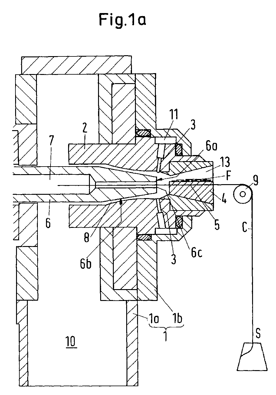
- Figure 1a-c shows a housing 1 with the housing parts 1a and 1b with a built-in nozzle block 2, which contains jet nozzles 3, by means of which a vortex flow is generated, and a so-called fiber and thread guide means 4, here with a conveying surface for conveying Fibers F drawn, with a guide 5 embedded therein for a continuous thread C, which can be pulled off a spool S via a deflection roller 9, for.
- the jet nozzles 3 generate the swirl flow for the twist, through which the fibers F supplied via the bevel guide means 4 are rotated in a direction of rotation around the end face 6a of the so-called spindle 6 and are guided into a yarn guide channel 7 of the spindle 6.
- the fibers F are conveyed in a fiber guide channel 13 on the aforementioned conveying surface of the fiber and thread guide means 4 against the end face 6a of the spindle 6 due to a sucked-in air.
- the sucked-in air takes place on the basis of an injector effect of the jet nozzles 3, which are provided in such a way that, on the one hand, the aforementioned air swirl is generated, but on the other hand, air is also sucked through the fiber guide channel 13.
- the compressed air for the jet nozzles 3 is fed uniformly to the jet nozzles by means of a compressed air distribution chamber 11. How the endless thread C can be inserted into the device is discussed below.
- the guide 5 for the continuous thread C is oriented such that it is inserted centrally or that the guided continuous thread C is inserted centrally into the inlet mouth 6c of the spindle 6.
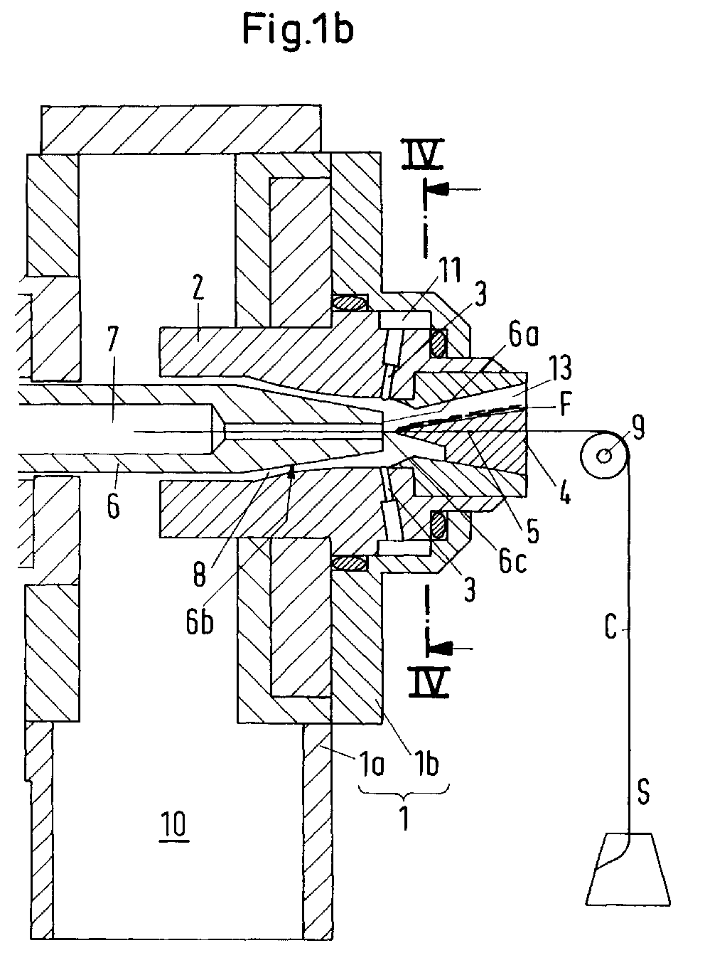
- the fiber and thread guide means 4 is preferably designed so that the fiber guide surface 28 comes to lie horizontally, as shown in Figure 1a , or the fiber and thread guide means 4 is against the end face 6a of the spindle, z. B. tapered on all, or only on some sides, as in Figure 1b.
- the guide 5 let into the fiber and thread guide means 4 can be a groove for receiving the endless thread C or a through hole through the fiber and thread guide means 4, through which the endless thread C is passed.
- a tube-like element 5c e.g. B.
- a tube provided with a continuous opening can be provided in the fiber and thread guiding means 4 ( FIG. 1c), which is preferably closer to the inlet opening 6c, and through which the continuous thread C is guided centrally to the inlet opening 6c.
- the tube-like element 5c is only part of the guide 5, the remaining guide 5 in the thread guide means 4 can be designed as a groove or bore. If the fiber and thread guide means 4 tapers towards the end face 6a of the spindle 6 or is provided with a tube-like element 5c, the fibers F are already very central to the yarn guide channel at the end of the fiber and thread guide means 4 or the tube-like element 5c 7 directed.
- FIGS. 2, 2a and 2c show a fiber delivery edge 29 which is very close to an inlet mouth 35 of a yarn guide channel 45 which is arranged within a so-called spindle 32.
- the fiber delivery edge 29 is arranged parallel to a center line 47 of the yarn guide channel 45 and this center line 47 with a predetermined distance A between the same and the inlet opening 35, and a predetermined distance B between an imaginary plane E containing the edge.
- the distance A corresponds to a range of 0.1 to 1.0 mm, depending on the type of fiber and average fiber length and corresponding test results.
- the distance B depends on a diameter G of the inlet mouth 35 and, depending on the test results, is within a range from 10 to 30% of the diameter G.
- the fiber delivery edge 29 has a length D.1 (FIG. 2a), which in is a ratio of 1: 5 to the diameter G of the yarn guide channel 45 and formed by an end face 30 of a fiber conveying element 27 (the fiber and thread guide means 4 according to FIGS. 1a-c) and a fiber guide surface 28 of the element 27 becomes.
- the end face 30, with a height O lies within the range of the Diameter G and has an empirically determined distance H between the plane E and the opposite inner wall 48 of the yarn guide channel 45.
- the fiber conveying element 27 also has a guide 5.1 (a groove, FIG. 2b) or 5.2 (a hole, Fig. 2b.1) for guiding the continuous thread C and is in a Nozzle block 20 guided support element 37 and forms with this Carrier element forming a fiber guide channel 26 and has at the entrance a fiber receiving edge 31, around which the fibers are guided by a Fiber feed roller 39 are fed.
- These fibers are from the Fiber conveyor roller 39 is lifted off the conveyor roller by means of a suction air flow and conveyed through the fiber guide channel 26.
- the suction air flow is created by an in Jet nozzles 21 with a blowing direction 38 generated air flow, due to a Injector.
- these jet nozzles are in a nozzle block 20 on the one hand with an angle ⁇ in order to produce the aforementioned injector effect and on the other hand, inclined at an angle ⁇ to create an air vortex, which has a direction of rotation 24 on a cone 36 of the fiber conveying element 27 rotates along and around spindle front surfaces 34, as mentioned below
- the fiber guide surface 28 has a recess 5.1 in the fiber guide direction for guiding the continuous thread C. (Fig. 2a from above, Fig. 2b in section). The endless thread C inserted and then wound around by the fibers F.
- those supplied by the fiber feed roller 39 are provided Fibers F by means of the suction air flow mentioned in the fiber guide channel 26, such as mentioned, lifted off the fiber conveyor roller 39 and on the fiber guide surface 28 in a conveying direction 25 together with the endless thread C against the Fiber delivery edge 29 out.
- One end of the Fibers are guided through the spindle inlet opening 35 into the yarn guide channel 45, while the other, second ends 49 of these fibers flip as soon as these second ends free and caught by the rotating air flow.
- the fibers in the yarn guide channel 45 around the endless thread C. In this way, a core yarn 46 is created, which has a yarn character similar to that Has ring yarn.
- This constriction occurs because the front ends, viewed in the direction of the fibers, which are already bound in the twisted yarn 46, have a tendency to migrate in the direction of the constriction, so that further second ends of fibers lying behind are also displaced in the direction of the constriction. However, this only happens until the second ends 49 of the fibers F are caught by the aforementioned air vortex, rotated around the spindle front surface 34 and drawn into the inlet mouth 35 at the thread take-off speed and thereby obtain the twist necessary for the yarn formation.
- the width d.1 is shown expanded by means of dash-dotted lines. On the one hand to show that this breadth can be expanded, on the other hand by to show that this expanded width d.1 may be the one shown in FIG. 2a Vortex chamber 22 is reduced, if not disruptively changed, by the Eddy current in it can no longer develop so that the fiber ends 49 with the desired energy can be captured by the eddy current. This must go with empirical experiments can be determined.
- the aforementioned yarn formation occurs after the start of a piecing process of a corresponding type, for example in which a yarn end already exists existing yarn back through the yarn guide channel 45 in the area of Spindle inlet mouth 35 is guided so far that fibers of this yarn end from already rotating airflow are opened so that new through the Fiber guiding channel 26 feed ends of fibers from this rotating Fiber structure can be captured.
- Yarn ends will be the following parts of the newly supplied fibers already around the ends located in the mouth part of the yarn guide channel can wind around, pulled, so that as a result the aforementioned yarn with an essentially predetermined approach can be spun again.
- the proposed device can be used to start the piecing process Continuous thread C from one end of the spinning device through the thread and Fiber guide means (4) and are injected through the yarn guide channel (46), so that he caught at the other end and z. B. attached to a wrap can.
- the fiber guide surface 28 or the fiber delivery edge 29 can be different be shaped, e.g. B. concave, convex or wavy. These forms serve the different fiber guidance on the fiber guide surface 28 and are depending Determine fiber type and fiber length empirically. It turned out that concave for so-called “slippery fibers” and convex for so-called “sticky” fibers. there one understands “slippery” fibers those, which a weak mutual Adhesion and "sticky” fibers are those that are mutually stronger Have adhesion.
- FIGS. 3a and 3b show a proposed solution for modifying the device shown above (FIGS. 2ff.) For inserting the continuous thread C before piecing.
- a nozzle block 20 according to FIGS. 2 and 2.1 can be seen.
- a part 20 'of the nozzle block 20 including the support element 37 can be opened along the line M in accordance with FIG. 2b and can be lifted off in such a way that the fiber guide surface 28 and the groove 5.1 made therein are freely accessible.
- a continuous thread C for the production of a core yarn can be inserted effortlessly without having to be threaded through the groove 5.1.
- the guide 5 in the form of a bore 5.2, as shown schematically in FIG.
- part of the fiber guide element 27 ' is folded down along the line M' in accordance with FIG. 2b.1.
- the hole 5.2 is thus exposed and the continuous thread C can be inserted.
- an upper or lower part of the nozzle block 20 is folded away according to the groove 5.1 or bore 5.2 present on the remaining length of the thread guide means 4.
- An endless thread C must be threaded or shot in through the tube-like element 5c in accordance with current technology; however, the distance is shortened by a short, tube-like element, smaller than the thread guiding means 4, and in the other two cases the insertion process is completely eliminated.
Landscapes
- Engineering & Computer Science (AREA)
- Mechanical Engineering (AREA)
- Textile Engineering (AREA)
- Spinning Or Twisting Of Yarns (AREA)
- Yarns And Mechanical Finishing Of Yarns Or Ropes (AREA)
- Nonwoven Fabrics (AREA)
Abstract
Description
Eine Vorrichtung, in welcher die Fasern für die Einbindung der vorderen Faserenden durch den hinteren Teil der Fasern in einer Faserführung geführt sind und mittels welcher die Fasern derart vom erzeugten Luftwirbel erfasst werden können, dass ein gleichmässiges und festes Garn erzeugt werden kann, ist in US 5,528,895 beschrieben. Zur Führung der Fasern ist ein zum Garnführungskanal zentrisch angeordneter Dorn vorgesehen, um welchen die zugelieferten Fasern spiralförmig in Richtung zum Garnführungskanal verlaufen, um versponnen zu werden. Diese zentrale Einrichtung verhindert das Einbringen eines Endlosfadens oder mehrerer solcher, der oder die zwingend durch das Zentrum des Garnführungskanals verlaufen müssen.
Die Aufgabe wird im Wesentlichen dadurch gelöst, dass eine Faserführungsfläche zu einer Spindel mit einem Garnführungskanal hin weist, über und durch welche die Fasern in einer im Wesentlichen flach nebeneinander liegenden Formation gegen die Einlassmündung des Garnführungskanals geführt werden und das Faserführungselement mit der Faserführungsfläche zusätzlich eine in ein Faser- und Fadenführungsmittel eingelassene Führung für den mindestens einen Endlosfaden aufweist, sodass dieser mindestens eine Endlosfaden von den Fasern an der Spindel umsponnen werden kann.
Im Folgenden wird die Erfindung anhand von lediglich Ausführungswege darstellenden Zeichnungen näher erläutert.
- Fig. 1a-1c
- Ausschnittsweise und in schematischer Form die wesentlichen Teile einer Vorrichtung zur,open-end' Core-Garn-Herstellung mit Zuführung eines Endlosfadens. Die Faserzuführung ist hier nicht gezeigt, sie wird im Zusammenhang mit den Figuren 2, 2a-c besprochen.
- Fig. 2, 2.1
- die Erfindung gemäss Figur 1a und 1b im Wesentlichen gemäss den Schnittlinien I-I (Fig. 2b) bzw. den Schnittlinien I'-I' in Fig. 2b.1, wobei ein mittleres Element nicht geschnitten dargestellt ist
- Fig. 2a, 2a.1
- einen Schnitt gemäss den Schnittlinien II-II von Fig. 2 bzw. II'-II' von Fig. 2.1
- Fig. 2b, 2b.1
- einen Querschnitt gemäss den Schnittlinien III-III von Fig. 2 bzw. III'-III' von Fig. 2.1
- Fig. 2c
- einen Ausschnitt aus Fig. 2, vergrössert dargestellt
- Fig. 3a, 3b
- Vorrichtungsvorschläge zum Einlegen der Endlosfaser im Zusammenhang mit Fig. 2 und 2b in schematischer Darstellung.
Die Strahldüsen 3 erzeugen die Wirbelströmung für den Drall durch welchen die über das Fasenführungsmittel 4 zugelieferten Fasern F in einem Drehsinn um die Stirnseite 6a der sogenannten Spindel 6 gedreht und in einen Garnführungskanal 7 der Spindel 6 hineingeführt werden. Die Fasern F werden in einem Faserführungskanal 13 auf der vorgenannten Förderfläche des Faser- und Fadenführungsmittels 4 aufgrund einer eingesaugten Luft gegen die Stirnseite 6a der Spindel 6 gefördert. Die eingesaugte Luft erfolgt aufgrund einer Injektorwirkung der Strahldüsen 3, welche derart vorgesehen sind, dass einerseits der genannte Luftwirbel erzeugt, aber andererseits auch Luft durch den Faserführungskanal 13 gesaugt wird. Diese Luft entweicht einem Konusteil 6b der Spindel 6 entlang durch einen Entlüftungshohlraum 8 in einen Luftauslass 10. Die Druckluft für die Strahldüsen 3 wird mittels eines Druckluftverteilraums 11 den Strahldüsen gleichmässig zugeführt.
Weiter unten wird darauf eingegangen, wie der Endlosfaden C in die Vorrichtung eingelegt werden kann. Die Führung 5 für den Endlosfaden C ist so ausgerichtet, dass sie zentrisch bzw. dass der geführte Endlosfaden C zentrisch in die Einlassmündung 6c der Spindel 6 eingeführt wird.
Dabei entspricht der Abstand A je nach Faserart und mittlerer Faserlänge und entsprechenden Versuchsresultaten einem Bereich von 0,1 bis 1,0 mm. Der Abstand B hängt von einem Durchmesser G der Einlassmündung 35 ab und liegt, je nach Versuchsresultaten, innerhalb eines Bereichs von 10 bis 30 % des genannten Durchmessers G.
Claims (15)
- Vorrichtung zur Herstellung eines gesponnenen Fadens aus einem Faserverband, welcher mindestens einen separat zugeführten endlosen Faden (C) zu einem Core-Garn (46) umspinnt, gekennzeichnet durch ein Faserführungsmittel (4) mit einem Faserführungskanal (13, 26) mit einer Faserführungsfläche (28) zur Führung von Fasern (F) des Faserverbands in eine Einlassmündung (6 c, 35) eines Garnführungskanals (7, 45), weiter umfassend eine Fluideinrichtung zur Erzeugung einer Wirbelströmung um die Einlassmündung (6 c, 35) des Garnführungskanals (7, 45), wobei die Faserführungsfläche (28) zum Garnführungskanal (7, 45) hinweist, über und durch welche die Fasern (F) gegen die Einlassmündung (6 c. 35) des Garnführungskanals (7, 45) führbar sind, weiter umfassend eine Führung (5, 5.1, 5.2, 5 c) für mindestens einen Endlosfaden (C), der von den Fasern (F) umsponnen wird.
- Vorrichtung nach Anspruch 1,
dadurch gekennzeichnet, dass die genannte Führung (5, 5.1, 5.2, 5 c) im Faser- und Fadenführungsmittel (4) enthalten ist. - Vorrichtung nach Anspruch 1,
dadurch gekennzeichnet, dass die Faserführungsfläche (28) des Faser- und Fadenführungsmittels (4) eine Faserabgabekante (29) aufweist. - Vorrichtung nach Anspruch 1 oder 3,
dadurch gekennzeichnet, dass das Faser- und Fadenführungsmittel (4) zur Einlassmündung (6 c, 35) der Spindel (6, 32) hin verjüngend gestaltet ist. - Vorrichtung nach Anspruch 1,
dadurch gekennzeichnet, dass das Faser- und Fadenführungsmittel (4) ein rohrähnliches Element (5 c) zum Führen mindestens eines Endlosfadens (C) beinhaltet. - Vorrichtung nach Anspruch 1-5,
dadurch gekennzeichnet, dass die Führung (5) ein in die Faserführungsfläche (28) eingelassenes Nut (5.1) beinhaltet, deren Achse in Richtung Fadenlauf im wesentlichen fluchtend in die Achse des Garnführungskanals (7, 45) übergeht. - Vorrichtung nach Anspruch 1-5,
dadurch gekennzeichnet, dass das rohrähnliche Element (5 c) eine unter der Faserführungsfläche (28) verlaufende Bohrung (5.2) ist, deren Achse in Richtung Fadenlauf im wesentlichen fluchtend in die Achse des Garnführungskanals (7, 45) übergeht. - Vorrichtung nach einem der Patentansprüche 1-7,
dadurch gekennzeichnet, dass zum Zweck des Einlegens mindestens eines Endlosfadens (C) Vorrichtungsteile am Fadenführungsmittel (4) von diesem wegbewegbar sind. - Vorrichtung nach Anspruch 8,
dadurch gekennzeichnet, dass die Vorrichtungsteile über oder unter dem rohrähnlichen Element (5 c) des Fadenführungsmittels (4) von diesem wegbewegbar sind. - Vorrichtung nach Patentanspruch 8 oder 9,
dadurch gekennzeichnet, dass die Vorrichtungsteile über einer Nut (5.1) des Fadenführungsmittels (4) von diesem wegbewegbar sind. - Vorrichtung nach Patentanspruch 8 oder 9,
dadurch gekennzeichnet, dass die Vorrichtungsteile unter einer Bohrung (5.2) des Fadenführungsmittels (4) von diesem wegbewegbar sind. - Verfahren zur Herstellung eines gesponnenen Fadens aus einem Faserverband, welcher mindestens einen separat zugeführten endlosen Faden (C) zu einem Core-Garn (46) umspinnt, mit einer Vorrichtung gemäss Anspruch 1,
dadurch gekennzeichnet, dass Fasern (F) des Faserverbandes mittels eines Faserführungskanals (13) und einer Faserführungsfläche (28) in eine Einlassmündung (6 c, 35) eines Garnführungskanals (7, 45) geführt werden und durch eine Fluideinrichtung zur Erzeugung einer Wirbelströmung um die Einlassmündung (6 c, 35) des Garnführungskanals (7, 45), um mindestens einen Endlosfaden (C) gesponnen werden, wobei der mindestens eine Endlosfaden (C) durch eine Führung (5), zur Einlassmündung (6 c, 35) des Garnführungskanals (7, 45) geführt wird. - Verfahren zur Herstellung eines gesponnenen Fadens aus einem Faserverband nach Anspruch 12,
dadurch gekennzeichnet, dass der mindestens eine Endlosfaden C zum Anspinnen in ein Faser- und Fadenführungsmittel (4) eingelegt wird. - Verfahren zur Herstellung eines gesponnenen Fadens aus einem Faserverband nach Anspruch 12,
dadurch gekennzeichnet, dass der mindestens eine Endlosfaden C zum Anspinnen in einen Garnführungskanal (7, 45) und in ein Faser- und Fadenführungsmittel (4) eingeschossen wird. - Verfahren zur Herstellung eines gesponnenen Fadens aus einem Faserverband nach Anspruch 12-14,
dadurch gekennzeichnet, dass der mindestens eine Endlosfaden (C) zum Anspinnen zumindest teilweise durch ein Faser- und Fadenführungsmittel (4) durchgeführt wird.
Applications Claiming Priority (2)
| Application Number | Priority Date | Filing Date | Title |
|---|---|---|---|
| CH25042000 | 2000-12-22 | ||
| CH25042000 | 2000-12-22 |
Publications (3)
| Publication Number | Publication Date |
|---|---|
| EP1223236A2 true EP1223236A2 (de) | 2002-07-17 |
| EP1223236A3 EP1223236A3 (de) | 2003-12-03 |
| EP1223236B1 EP1223236B1 (de) | 2013-05-29 |
Family
ID=4569703
Family Applications (1)
| Application Number | Title | Priority Date | Filing Date |
|---|---|---|---|
| EP01130244.5A Expired - Lifetime EP1223236B1 (de) | 2000-12-22 | 2001-12-19 | Vorrichtung zur Herstellung eines Core-Garns |
Country Status (6)
| Country | Link |
|---|---|
| US (1) | US6782685B2 (de) |
| EP (1) | EP1223236B1 (de) |
| JP (1) | JP4310061B2 (de) |
| CN (1) | CN100445441C (de) |
| ES (1) | ES2425214T3 (de) |
| PT (1) | PT1223236E (de) |
Cited By (2)
| Publication number | Priority date | Publication date | Assignee | Title |
|---|---|---|---|---|
| EP2813604A1 (de) * | 2013-06-14 | 2014-12-17 | Maschinenfabrik Rieter Ag | Spinndüse sowie damit ausgerüstete Spinnstelle einer Luftspinnmaschine |
| EP2980284A3 (de) * | 2014-07-29 | 2016-03-16 | Saurer Germany GmbH & Co. KG | Verfahren zur herstellung eines luftgesponnenen garnes |
Families Citing this family (21)
| Publication number | Priority date | Publication date | Assignee | Title |
|---|---|---|---|---|
| JP4062869B2 (ja) * | 2000-09-01 | 2008-03-19 | 村田機械株式会社 | コアヤーン製造装置及びコアヤーン製造方法 |
| EP1217109A3 (de) * | 2000-12-22 | 2003-04-02 | Maschinenfabrik Rieter Ag | Spinnvorrichtung |
| US20020152739A1 (en) * | 2000-12-22 | 2002-10-24 | Maschinenfabrik Rieter Ag | Spinning device |
| US20020139102A1 (en) * | 2001-03-29 | 2002-10-03 | Murata Kikai Kabushiki Kaisha | Core yarn, and method and device for manufacturing the same |
| ATE338838T1 (de) * | 2002-03-20 | 2006-09-15 | Rieter Ag Maschf | Luftspinnvorrichtung mit kanalauskleidung |
| EP2145034B1 (de) | 2007-04-17 | 2016-11-23 | International Textile Group, Inc. | Denimgewebe |
| JP5333987B2 (ja) * | 2008-12-19 | 2013-11-06 | 村田機械株式会社 | 空気紡績機 |
| JP5549551B2 (ja) * | 2010-11-10 | 2014-07-16 | 村田機械株式会社 | 空気紡績装置を用いた紡績方法及び空気紡績装置 |
| CN103215700B (zh) * | 2013-04-18 | 2016-01-06 | 武汉纺织大学 | 一种生产花式纱的涡流复合纺纱方法 |
| CN103938327B (zh) * | 2014-03-27 | 2016-03-30 | 吴江明佳织造有限公司 | 双支管包缠纱供纱气管 |
| CH709953A1 (de) * | 2014-07-30 | 2016-02-15 | Rieter Ag Maschf | Verfahren zum Betrieb einer Luftspinnmaschine. |
| CN105088437A (zh) * | 2015-09-25 | 2015-11-25 | 郑世浦 | 液压驱动升降且可更换过滤网的纺织用气流搓捻装置 |
| CH712663A1 (de) * | 2016-07-14 | 2018-01-15 | Rieter Ag Maschf | Verfahren zum Verarbeiten eines strangförmigen Faserverbands sowie Vorspinnmaschine. |
| CN108018625B (zh) * | 2017-12-20 | 2020-05-26 | 东华大学 | 喷气涡流纺纱装置中纤维导引体及其制造方法 |
| CN107904710A (zh) * | 2017-12-21 | 2018-04-13 | 苏州市星京泽纤维科技有限公司 | 一种新型涡流纺纱喷嘴结构 |
| EP3835467B1 (de) * | 2019-12-09 | 2025-07-02 | Saurer Intelligent Technology AG | Verfahren zur reinigung einer luftspinnvorrichtung einer spinnstelle und eine solche luftspinnvorrichtung |
| CN111005111B (zh) * | 2019-12-26 | 2021-08-17 | 湖北枫树线业有限公司 | 一种喷气涡流纺制备再生涤纶包芯缝纫线的方法 |
| CN112708977A (zh) * | 2020-12-08 | 2021-04-27 | 苏州维杰纺织有限公司 | 一种疏水纳米纤维混纺纱及其生产工艺 |
| DE102020133359A1 (de) * | 2020-12-14 | 2022-06-15 | Saurer Spinning Solutions Gmbh & Co. Kg | Multifunktionsdüse für eine Spinnmaschine |
| DE102022114064A1 (de) | 2022-06-03 | 2023-12-14 | Saurer Spinning Solutions Gmbh & Co. Kg | Fadenabzugsdüse sowie Offenend-Spinnvorrichtung mit einer Fadenabzugsdüse |
| CN116288846B (zh) * | 2023-03-22 | 2024-05-28 | 宁波三邦超细纤维有限公司 | 一种长丝高强力涤纶缝纫线加工方法 |
Family Cites Families (10)
| Publication number | Priority date | Publication date | Assignee | Title |
|---|---|---|---|---|
| BE905590A (fr) | 1985-10-19 | 1987-02-02 | Barmag Barmer Maschf | Procede d'insertion d'un fil dans une filiere de texturisation. |
| JPH0465535A (ja) * | 1990-07-04 | 1992-03-02 | Murata Mach Ltd | 紡績装置 |
| JPH0620466U (ja) * | 1992-03-13 | 1994-03-18 | 村田機械株式会社 | 紡績装置 |
| JP2697575B2 (ja) * | 1993-09-08 | 1998-01-14 | 村田機械株式会社 | 紡績装置 |
| JP2708001B2 (ja) | 1995-02-10 | 1998-02-04 | 村田機械株式会社 | 紡績機の糸継ぎ装置 |
| DE19804341A1 (de) | 1998-02-05 | 1999-08-12 | Rieter Ag Maschf | Verfahren zur Herstellung eines Umwindegarns, Spinnmaschine zur Durchführung des Verfahrens sowie entsprechend hergestelltes Garn |
| EP0990719B1 (de) * | 1998-10-02 | 2003-05-28 | W. SCHLAFHORST AG & CO. | Spinnvorrichtung |
| DE19927838B4 (de) | 1999-06-18 | 2008-01-31 | Oerlikon Textile Gmbh & Co. Kg | Vorrichtung zur Herstellung gesponnener Fäden |
| JP3552618B2 (ja) | 1999-12-13 | 2004-08-11 | 村田機械株式会社 | コアヤーン製造方法および装置 |
| JP4062869B2 (ja) | 2000-09-01 | 2008-03-19 | 村田機械株式会社 | コアヤーン製造装置及びコアヤーン製造方法 |
-
2001
- 2001-12-18 US US10/022,811 patent/US6782685B2/en not_active Expired - Fee Related
- 2001-12-19 EP EP01130244.5A patent/EP1223236B1/de not_active Expired - Lifetime
- 2001-12-19 PT PT1130244T patent/PT1223236E/pt unknown
- 2001-12-19 ES ES01130244T patent/ES2425214T3/es not_active Expired - Lifetime
- 2001-12-21 CN CNB011457341A patent/CN100445441C/zh not_active Expired - Fee Related
- 2001-12-25 JP JP2001392533A patent/JP4310061B2/ja not_active Expired - Fee Related
Cited By (2)
| Publication number | Priority date | Publication date | Assignee | Title |
|---|---|---|---|---|
| EP2813604A1 (de) * | 2013-06-14 | 2014-12-17 | Maschinenfabrik Rieter Ag | Spinndüse sowie damit ausgerüstete Spinnstelle einer Luftspinnmaschine |
| EP2980284A3 (de) * | 2014-07-29 | 2016-03-16 | Saurer Germany GmbH & Co. KG | Verfahren zur herstellung eines luftgesponnenen garnes |
Also Published As
| Publication number | Publication date |
|---|---|
| EP1223236A3 (de) | 2003-12-03 |
| JP4310061B2 (ja) | 2009-08-05 |
| PT1223236E (pt) | 2013-08-22 |
| CN1362549A (zh) | 2002-08-07 |
| US6782685B2 (en) | 2004-08-31 |
| ES2425214T3 (es) | 2013-10-14 |
| JP2002227052A (ja) | 2002-08-14 |
| US20020124543A1 (en) | 2002-09-12 |
| CN100445441C (zh) | 2008-12-24 |
| EP1223236B1 (de) | 2013-05-29 |
Similar Documents
| Publication | Publication Date | Title |
|---|---|---|
| EP1223236B1 (de) | Vorrichtung zur Herstellung eines Core-Garns | |
| DE19603291B4 (de) | Pneumatische Spinnvorrichtung | |
| DE4431761A1 (de) | Spinnvorrichtung | |
| EP1926848A1 (de) | Luftdüsenaggregat für eine luftdüsenspinnvorrichtung | |
| EP1332248B9 (de) | Spinnvorrichtung | |
| EP1644561B1 (de) | Vorrichtung zum herstellen eines gesponnenen fadens aus einem stapelfaserverband | |
| EP3449048A1 (de) | Luftspinnmaschine sowie verfahren zur herstellung eines garns | |
| EP0321885A1 (de) | Falschdrall-Luftdüse | |
| DE3207136A1 (de) | Verfahren und vorrichtung zum herstellen eines fadens | |
| DE3639031C2 (de) | ||
| DE4131059A1 (de) | Spinnvorrichtung | |
| EP1778901A1 (de) | Spindel mit injektorkanal und verfahren zum ansetzen für eine luftspinnmaschine. | |
| EP1415027B1 (de) | Vorrichtung zur herstellung eines gesponnenen garnes | |
| DE102020133359A1 (de) | Multifunktionsdüse für eine Spinnmaschine | |
| DE3813720A1 (de) | Verfahren zum einleiten des betriebes einer spinnmaschine | |
| DE3346045A1 (de) | Verfahren zum spinnen von garn aus stapelfasern in einem luftwirbel und vorrichtung zur durchfuehrung dieses verfahrens | |
| EP3464691B1 (de) | Garnbildungselement für eine vorspinnmaschine sowie damit ausgerüstete vorspinnmaschine | |
| EP0222101B1 (de) | Verfahren zum Anspinnen eines Garnes an einer Friktionsspinnvorrichtung | |
| DE4222662B4 (de) | Vorrichtung zum Vorbereiten von Fadenenden | |
| EP0415295B1 (de) | Verfahren zum Falschdrahtspinnen und Vorrichtung zur Durchführung des Verfahrens | |
| EP1587974B1 (de) | Vorrichtung zum herstellen eines gesponnenen fadens | |
| CH676725A5 (de) | ||
| CH678734A5 (de) | ||
| DE3920813A1 (de) | Verfahren zum verspinnen von aufgeloesten fasern von linearer textiler struktur auf der grundlage von diskontinuierlichen fasern, und vorrichtung zur durchfuehrung des verfahrens | |
| EP0363649B1 (de) | Friktionsspinnvorrichtung |
Legal Events
| Date | Code | Title | Description |
|---|---|---|---|
| PUAI | Public reference made under article 153(3) epc to a published international application that has entered the european phase |
Free format text: ORIGINAL CODE: 0009012 |
|
| AK | Designated contracting states |
Kind code of ref document: A2 Designated state(s): AT BE CH CY DE DK ES FI FR GB GR IE IT LI LU MC NL PT SE TR |
|
| AX | Request for extension of the european patent |
Free format text: AL;LT;LV;MK;RO;SI |
|
| PUAL | Search report despatched |
Free format text: ORIGINAL CODE: 0009013 |
|
| AK | Designated contracting states |
Kind code of ref document: A3 Designated state(s): AT BE CH CY DE DK ES FI FR GB GR IE IT LI LU MC NL PT SE TR |
|
| AX | Request for extension of the european patent |
Extension state: AL LT LV MK RO SI |
|
| 17P | Request for examination filed |
Effective date: 20040602 |
|
| AKX | Designation fees paid |
Designated state(s): AT BE CH CY DE DK ES FI FR GB GR IE IT LI LU MC NL PT SE TR |
|
| 17Q | First examination report despatched |
Effective date: 20100414 |
|
| REG | Reference to a national code |
Ref country code: DE Ref legal event code: R079 Ref document number: 50116290 Country of ref document: DE Free format text: PREVIOUS MAIN CLASS: D01H0004020000 Ipc: D01H0001115000 |
|
| RIC1 | Information provided on ipc code assigned before grant |
Ipc: D01H 4/38 20060101ALI20121010BHEP Ipc: D01H 1/115 20060101AFI20121010BHEP Ipc: D01H 4/02 20060101ALI20121010BHEP |
|
| GRAP | Despatch of communication of intention to grant a patent |
Free format text: ORIGINAL CODE: EPIDOSNIGR1 |
|
| GRAS | Grant fee paid |
Free format text: ORIGINAL CODE: EPIDOSNIGR3 |
|
| GRAA | (expected) grant |
Free format text: ORIGINAL CODE: 0009210 |
|
| AK | Designated contracting states |
Kind code of ref document: B1 Designated state(s): AT BE CH CY DE DK ES FI FR GB GR IE IT LI LU MC NL PT SE TR |
|
| REG | Reference to a national code |
Ref country code: GB Ref legal event code: FG4D Free format text: NOT ENGLISH |
|
| REG | Reference to a national code |
Ref country code: CH Ref legal event code: EP |
|
| REG | Reference to a national code |
Ref country code: AT Ref legal event code: REF Ref document number: 614471 Country of ref document: AT Kind code of ref document: T Effective date: 20130615 |
|
| REG | Reference to a national code |
Ref country code: IE Ref legal event code: FG4D Free format text: LANGUAGE OF EP DOCUMENT: GERMAN |
|
| REG | Reference to a national code |
Ref country code: DE Ref legal event code: R096 Ref document number: 50116290 Country of ref document: DE Effective date: 20130725 |
|
| REG | Reference to a national code |
Ref country code: PT Ref legal event code: SC4A Free format text: AVAILABILITY OF NATIONAL TRANSLATION Effective date: 20130801 |
|
| REG | Reference to a national code |
Ref country code: ES Ref legal event code: FG2A Ref document number: 2425214 Country of ref document: ES Kind code of ref document: T3 Effective date: 20131014 |
|
| PG25 | Lapsed in a contracting state [announced via postgrant information from national office to epo] |
Ref country code: GR Free format text: LAPSE BECAUSE OF FAILURE TO SUBMIT A TRANSLATION OF THE DESCRIPTION OR TO PAY THE FEE WITHIN THE PRESCRIBED TIME-LIMIT Effective date: 20130830 Ref country code: FI Free format text: LAPSE BECAUSE OF FAILURE TO SUBMIT A TRANSLATION OF THE DESCRIPTION OR TO PAY THE FEE WITHIN THE PRESCRIBED TIME-LIMIT Effective date: 20130529 Ref country code: SE Free format text: LAPSE BECAUSE OF FAILURE TO SUBMIT A TRANSLATION OF THE DESCRIPTION OR TO PAY THE FEE WITHIN THE PRESCRIBED TIME-LIMIT Effective date: 20130529 |
|
| REG | Reference to a national code |
Ref country code: NL Ref legal event code: VDEP Effective date: 20130529 |
|
| PG25 | Lapsed in a contracting state [announced via postgrant information from national office to epo] |
Ref country code: DK Free format text: LAPSE BECAUSE OF FAILURE TO SUBMIT A TRANSLATION OF THE DESCRIPTION OR TO PAY THE FEE WITHIN THE PRESCRIBED TIME-LIMIT Effective date: 20130529 |
|
| PGFP | Annual fee paid to national office [announced via postgrant information from national office to epo] |
Ref country code: AT Payment date: 20131223 Year of fee payment: 13 Ref country code: PT Payment date: 20131121 Year of fee payment: 13 |
|
| PG25 | Lapsed in a contracting state [announced via postgrant information from national office to epo] |
Ref country code: NL Free format text: LAPSE BECAUSE OF FAILURE TO SUBMIT A TRANSLATION OF THE DESCRIPTION OR TO PAY THE FEE WITHIN THE PRESCRIBED TIME-LIMIT Effective date: 20130529 |
|
| PGFP | Annual fee paid to national office [announced via postgrant information from national office to epo] |
Ref country code: IT Payment date: 20131217 Year of fee payment: 13 Ref country code: ES Payment date: 20131219 Year of fee payment: 13 |
|
| PLBE | No opposition filed within time limit |
Free format text: ORIGINAL CODE: 0009261 |
|
| STAA | Information on the status of an ep patent application or granted ep patent |
Free format text: STATUS: NO OPPOSITION FILED WITHIN TIME LIMIT |
|
| 26N | No opposition filed |
Effective date: 20140303 |
|
| REG | Reference to a national code |
Ref country code: DE Ref legal event code: R097 Ref document number: 50116290 Country of ref document: DE Effective date: 20140303 |
|
| BERE | Be: lapsed |
Owner name: MASCHINENFABRIK RIETER A.G. Effective date: 20131231 |
|
| REG | Reference to a national code |
Ref country code: CH Ref legal event code: PL |
|
| GBPC | Gb: european patent ceased through non-payment of renewal fee |
Effective date: 20131219 |
|
| PG25 | Lapsed in a contracting state [announced via postgrant information from national office to epo] |
Ref country code: MC Free format text: LAPSE BECAUSE OF FAILURE TO SUBMIT A TRANSLATION OF THE DESCRIPTION OR TO PAY THE FEE WITHIN THE PRESCRIBED TIME-LIMIT Effective date: 20130529 Ref country code: LU Free format text: LAPSE BECAUSE OF FAILURE TO SUBMIT A TRANSLATION OF THE DESCRIPTION OR TO PAY THE FEE WITHIN THE PRESCRIBED TIME-LIMIT Effective date: 20131219 |
|
| REG | Reference to a national code |
Ref country code: IE Ref legal event code: MM4A |
|
| REG | Reference to a national code |
Ref country code: FR Ref legal event code: ST Effective date: 20140829 |
|
| PG25 | Lapsed in a contracting state [announced via postgrant information from national office to epo] |
Ref country code: IE Free format text: LAPSE BECAUSE OF NON-PAYMENT OF DUE FEES Effective date: 20131219 Ref country code: BE Free format text: LAPSE BECAUSE OF NON-PAYMENT OF DUE FEES Effective date: 20131231 Ref country code: CH Free format text: LAPSE BECAUSE OF NON-PAYMENT OF DUE FEES Effective date: 20131231 Ref country code: LI Free format text: LAPSE BECAUSE OF NON-PAYMENT OF DUE FEES Effective date: 20131231 |
|
| PG25 | Lapsed in a contracting state [announced via postgrant information from national office to epo] |
Ref country code: GB Free format text: LAPSE BECAUSE OF NON-PAYMENT OF DUE FEES Effective date: 20131219 Ref country code: FR Free format text: LAPSE BECAUSE OF NON-PAYMENT OF DUE FEES Effective date: 20131231 |
|
| PGFP | Annual fee paid to national office [announced via postgrant information from national office to epo] |
Ref country code: DE Payment date: 20141222 Year of fee payment: 14 |
|
| REG | Reference to a national code |
Ref country code: PT Ref legal event code: MM4A Free format text: LAPSE DUE TO NON-PAYMENT OF FEES Effective date: 20150619 |
|
| PG25 | Lapsed in a contracting state [announced via postgrant information from national office to epo] |
Ref country code: CY Free format text: LAPSE BECAUSE OF FAILURE TO SUBMIT A TRANSLATION OF THE DESCRIPTION OR TO PAY THE FEE WITHIN THE PRESCRIBED TIME-LIMIT Effective date: 20130529 Ref country code: TR Free format text: LAPSE BECAUSE OF FAILURE TO SUBMIT A TRANSLATION OF THE DESCRIPTION OR TO PAY THE FEE WITHIN THE PRESCRIBED TIME-LIMIT Effective date: 20130529 |
|
| PG25 | Lapsed in a contracting state [announced via postgrant information from national office to epo] |
Ref country code: PT Free format text: LAPSE BECAUSE OF NON-PAYMENT OF DUE FEES Effective date: 20150619 |
|
| REG | Reference to a national code |
Ref country code: AT Ref legal event code: MM01 Ref document number: 614471 Country of ref document: AT Kind code of ref document: T Effective date: 20141219 |
|
| PG25 | Lapsed in a contracting state [announced via postgrant information from national office to epo] |
Ref country code: AT Free format text: LAPSE BECAUSE OF NON-PAYMENT OF DUE FEES Effective date: 20141219 |
|
| PG25 | Lapsed in a contracting state [announced via postgrant information from national office to epo] |
Ref country code: IT Free format text: LAPSE BECAUSE OF NON-PAYMENT OF DUE FEES Effective date: 20141219 |
|
| REG | Reference to a national code |
Ref country code: ES Ref legal event code: FD2A Effective date: 20160129 |
|
| PG25 | Lapsed in a contracting state [announced via postgrant information from national office to epo] |
Ref country code: ES Free format text: LAPSE BECAUSE OF NON-PAYMENT OF DUE FEES Effective date: 20141220 |
|
| REG | Reference to a national code |
Ref country code: DE Ref legal event code: R119 Ref document number: 50116290 Country of ref document: DE |
|
| PG25 | Lapsed in a contracting state [announced via postgrant information from national office to epo] |
Ref country code: DE Free format text: LAPSE BECAUSE OF NON-PAYMENT OF DUE FEES Effective date: 20160701 |