EP1221628B1 - Tube à transmission optique, procédé de sa fabrication et système d'éclairage linéaire - Google Patents
Tube à transmission optique, procédé de sa fabrication et système d'éclairage linéaire Download PDFInfo
- Publication number
- EP1221628B1 EP1221628B1 EP02005409A EP02005409A EP1221628B1 EP 1221628 B1 EP1221628 B1 EP 1221628B1 EP 02005409 A EP02005409 A EP 02005409A EP 02005409 A EP02005409 A EP 02005409A EP 1221628 B1 EP1221628 B1 EP 1221628B1
- Authority
- EP
- European Patent Office
- Prior art keywords
- cladding
- optical transmission
- light
- core
- tube
- Prior art date
- Legal status (The legal status is an assumption and is not a legal conclusion. Google has not performed a legal analysis and makes no representation as to the accuracy of the status listed.)
- Expired - Lifetime
Links
Images


Classifications
-
- B—PERFORMING OPERATIONS; TRANSPORTING
- B60—VEHICLES IN GENERAL
- B60Q—ARRANGEMENT OF SIGNALLING OR LIGHTING DEVICES, THE MOUNTING OR SUPPORTING THEREOF OR CIRCUITS THEREFOR, FOR VEHICLES IN GENERAL
- B60Q1/00—Arrangement of optical signalling or lighting devices, the mounting or supporting thereof or circuits therefor
- B60Q1/26—Arrangement of optical signalling or lighting devices, the mounting or supporting thereof or circuits therefor the devices being primarily intended to indicate the vehicle, or parts thereof, or to give signals, to other traffic
- B60Q1/32—Arrangement of optical signalling or lighting devices, the mounting or supporting thereof or circuits therefor the devices being primarily intended to indicate the vehicle, or parts thereof, or to give signals, to other traffic for indicating vehicle sides, e.g. clearance lights
- B60Q1/323—Arrangement of optical signalling or lighting devices, the mounting or supporting thereof or circuits therefor the devices being primarily intended to indicate the vehicle, or parts thereof, or to give signals, to other traffic for indicating vehicle sides, e.g. clearance lights on or for doors
-
- B—PERFORMING OPERATIONS; TRANSPORTING
- B60—VEHICLES IN GENERAL
- B60Q—ARRANGEMENT OF SIGNALLING OR LIGHTING DEVICES, THE MOUNTING OR SUPPORTING THEREOF OR CIRCUITS THEREFOR, FOR VEHICLES IN GENERAL
- B60Q3/00—Arrangement of lighting devices for vehicle interiors; Lighting devices specially adapted for vehicle interiors
- B60Q3/60—Arrangement of lighting devices for vehicle interiors; Lighting devices specially adapted for vehicle interiors characterised by optical aspects
- B60Q3/62—Arrangement of lighting devices for vehicle interiors; Lighting devices specially adapted for vehicle interiors characterised by optical aspects using light guides
- B60Q3/64—Arrangement of lighting devices for vehicle interiors; Lighting devices specially adapted for vehicle interiors characterised by optical aspects using light guides for a single lighting device
-
- B—PERFORMING OPERATIONS; TRANSPORTING
- B60—VEHICLES IN GENERAL
- B60Q—ARRANGEMENT OF SIGNALLING OR LIGHTING DEVICES, THE MOUNTING OR SUPPORTING THEREOF OR CIRCUITS THEREFOR, FOR VEHICLES IN GENERAL
- B60Q3/00—Arrangement of lighting devices for vehicle interiors; Lighting devices specially adapted for vehicle interiors
- B60Q3/70—Arrangement of lighting devices for vehicle interiors; Lighting devices specially adapted for vehicle interiors characterised by the purpose
- B60Q3/78—Arrangement of lighting devices for vehicle interiors; Lighting devices specially adapted for vehicle interiors characterised by the purpose for generating luminous strips, e.g. for marking trim component edges
-
- B—PERFORMING OPERATIONS; TRANSPORTING
- B60—VEHICLES IN GENERAL
- B60Q—ARRANGEMENT OF SIGNALLING OR LIGHTING DEVICES, THE MOUNTING OR SUPPORTING THEREOF OR CIRCUITS THEREFOR, FOR VEHICLES IN GENERAL
- B60Q7/00—Arrangement or adaptation of portable emergency signal devices on vehicles
-
- G—PHYSICS
- G02—OPTICS
- G02B—OPTICAL ELEMENTS, SYSTEMS OR APPARATUS
- G02B6/00—Light guides; Structural details of arrangements comprising light guides and other optical elements, e.g. couplings
- G02B6/0001—Light guides; Structural details of arrangements comprising light guides and other optical elements, e.g. couplings specially adapted for lighting devices or systems
- G02B6/0005—Light guides; Structural details of arrangements comprising light guides and other optical elements, e.g. couplings specially adapted for lighting devices or systems the light guides being of the fibre type
- G02B6/001—Light guides; Structural details of arrangements comprising light guides and other optical elements, e.g. couplings specially adapted for lighting devices or systems the light guides being of the fibre type the light being emitted along at least a portion of the lateral surface of the fibre
-
- G—PHYSICS
- G02—OPTICS
- G02B—OPTICAL ELEMENTS, SYSTEMS OR APPARATUS
- G02B6/00—Light guides; Structural details of arrangements comprising light guides and other optical elements, e.g. couplings
- G02B6/02—Optical fibres with cladding with or without a coating
- G02B6/02033—Core or cladding made from organic material, e.g. polymeric material
-
- G—PHYSICS
- G02—OPTICS
- G02B—OPTICAL ELEMENTS, SYSTEMS OR APPARATUS
- G02B6/00—Light guides; Structural details of arrangements comprising light guides and other optical elements, e.g. couplings
- G02B6/24—Coupling light guides
- G02B6/42—Coupling light guides with opto-electronic elements
- G02B6/4298—Coupling light guides with opto-electronic elements coupling with non-coherent light sources and/or radiation detectors, e.g. lamps, incandescent bulbs, scintillation chambers
-
- F—MECHANICAL ENGINEERING; LIGHTING; HEATING; WEAPONS; BLASTING
- F21—LIGHTING
- F21S—NON-PORTABLE LIGHTING DEVICES; SYSTEMS THEREOF; VEHICLE LIGHTING DEVICES SPECIALLY ADAPTED FOR VEHICLE EXTERIORS
- F21S9/00—Lighting devices with a built-in power supply; Systems employing lighting devices with a built-in power supply
- F21S9/02—Lighting devices with a built-in power supply; Systems employing lighting devices with a built-in power supply the power supply being a battery or accumulator
- F21S9/022—Emergency lighting devices
-
- F—MECHANICAL ENGINEERING; LIGHTING; HEATING; WEAPONS; BLASTING
- F21—LIGHTING
- F21W—INDEXING SCHEME ASSOCIATED WITH SUBCLASSES F21K, F21L, F21S and F21V, RELATING TO USES OR APPLICATIONS OF LIGHTING DEVICES OR SYSTEMS
- F21W2111/00—Use or application of lighting devices or systems for signalling, marking or indicating, not provided for in codes F21W2102/00 – F21W2107/00
- F21W2111/02—Use or application of lighting devices or systems for signalling, marking or indicating, not provided for in codes F21W2102/00 – F21W2107/00 for roads, paths or the like
- F21W2111/027—Use or application of lighting devices or systems for signalling, marking or indicating, not provided for in codes F21W2102/00 – F21W2107/00 for roads, paths or the like for indicating kerbs, steps or stairs
-
- F—MECHANICAL ENGINEERING; LIGHTING; HEATING; WEAPONS; BLASTING
- F21—LIGHTING
- F21Y—INDEXING SCHEME ASSOCIATED WITH SUBCLASSES F21K, F21L, F21S and F21V, RELATING TO THE FORM OR THE KIND OF THE LIGHT SOURCES OR OF THE COLOUR OF THE LIGHT EMITTED
- F21Y2115/00—Light-generating elements of semiconductor light sources
- F21Y2115/10—Light-emitting diodes [LED]
-
- G—PHYSICS
- G02—OPTICS
- G02B—OPTICAL ELEMENTS, SYSTEMS OR APPARATUS
- G02B6/00—Light guides; Structural details of arrangements comprising light guides and other optical elements, e.g. couplings
- G02B6/0001—Light guides; Structural details of arrangements comprising light guides and other optical elements, e.g. couplings specially adapted for lighting devices or systems
- G02B6/0011—Light guides; Structural details of arrangements comprising light guides and other optical elements, e.g. couplings specially adapted for lighting devices or systems the light guides being planar or of plate-like form
- G02B6/0033—Means for improving the coupling-out of light from the light guide
- G02B6/005—Means for improving the coupling-out of light from the light guide provided by one optical element, or plurality thereof, placed on the light output side of the light guide
- G02B6/0055—Reflecting element, sheet or layer
-
- G—PHYSICS
- G02—OPTICS
- G02B—OPTICAL ELEMENTS, SYSTEMS OR APPARATUS
- G02B6/00—Light guides; Structural details of arrangements comprising light guides and other optical elements, e.g. couplings
- G02B6/24—Coupling light guides
- G02B6/26—Optical coupling means
- G02B6/28—Optical coupling means having data bus means, i.e. plural waveguides interconnected and providing an inherently bidirectional system by mixing and splitting signals
- G02B6/2804—Optical coupling means having data bus means, i.e. plural waveguides interconnected and providing an inherently bidirectional system by mixing and splitting signals forming multipart couplers without wavelength selective elements, e.g. "T" couplers, star couplers
- G02B6/2817—Optical coupling means having data bus means, i.e. plural waveguides interconnected and providing an inherently bidirectional system by mixing and splitting signals forming multipart couplers without wavelength selective elements, e.g. "T" couplers, star couplers using reflective elements to split or combine optical signals
-
- Y—GENERAL TAGGING OF NEW TECHNOLOGICAL DEVELOPMENTS; GENERAL TAGGING OF CROSS-SECTIONAL TECHNOLOGIES SPANNING OVER SEVERAL SECTIONS OF THE IPC; TECHNICAL SUBJECTS COVERED BY FORMER USPC CROSS-REFERENCE ART COLLECTIONS [XRACs] AND DIGESTS
- Y10—TECHNICAL SUBJECTS COVERED BY FORMER USPC
- Y10S—TECHNICAL SUBJECTS COVERED BY FORMER USPC CROSS-REFERENCE ART COLLECTIONS [XRACs] AND DIGESTS
- Y10S385/00—Optical waveguides
- Y10S385/901—Illuminating or display apparatus
Definitions
- This invention relates to an optical transmission tube comprising a tubular transparent cladding and a transparent core having a higher index of refraction than the cladding and a method for preparing the same.
- it relates to an optical transmission tube allowing directional light emergence from one side or outer surface area of the cladding, and to a linear illuminant system having improved water resistance, improved environmental resistance and a low power consumption for driving.
- optical transmission tubes comprising a tubular cladding and a core in the cladding having a higher index of refraction than the cladding are generally designed so as to transmit as much light as possible from one end to the other end thereof, only a low luminance is generally available near the side surface of the tube.
- One possible measure for increasing the luminance at the side surface of an optical transmission tube is by corrugating the cladding inner surface to scatter light. This measure is difficult to apply in that method for producing an optical transmission tube which fills a tubular cladding with a core-forming polymerizable monomer liquid and pressurises the liquid to cause the monomer to polymerize,because the cladding is likely to rupture.
- disperse scattering particles in the core for increasing the luminance at the side surface of an optical transmission tube. It may occur to those skilled in the art to disperse scattering particles in a monomer liquid and then polymerize and solidify the monomer. However, there has never been available a method of adding scattering particles to a monomeric liquid and polymerizing the liquid in a controlled manner such that the scattering particles are distributed in a limited area, that is, so as to form a reflecting layer, at the end of polymerization.
- US 4,733,332 increases the luminance at the side surface of an optical transmission tube by adhering a fine powder of high refractive index in a diffusion pattern to the outer surface of a light-transmitting rod which is surrounded with a transparent protection tube, with clearance between the rod and the tube.
- EP-A-0 131 058 discloses a method or preparing an optical fiber or a bundle of optical fibers comprising a core, a cladding and an embedding material.
- US-A-4 806 289 describes the method of making a hollow light conductor made of an annular core encased between inner and outer claddings. In both documents, the light transmission tubes/fibers are prepared by extrusion.
- Neon tubes and fluorescent tubes require high voltages, with the risk of electric shocks and leakage. They cannot be used in water and at places where rain or snow reaches. Since the tubes are formed of glass, they cannot be used at places where failure of glass tubes by physical collision of people or vehicles is expectable.
- the glass tubes must be worked to the desired curvature, which requires skilled workers and hence, leads to an increased cost.
- the power consumption of neon tubes and fluorescent tubes is as high as several tens of watts per meter. For a long term of operation, they must be installed where a commercial power supply is available.
- optical transmission tubes in the form of a flexible tube filled with a transparent core liquid or flexible transparent polymer and strands of plastic optical fibers have been proposed.
- the system includes a light source and an optical transmission tube which receives light from the light source at one end thereof.
- the optical transmission tube is designed such that light may emerge from a side surface area of the tube over a length of several tens of meters. Since the light source can be remote from the light emerging area, this system can be used in water, outdoor or even in an environment with the risk of explosion.
- the system is free of the risk of breakage, eliminates complex cumbersome working such as glass working, and is readily applied at a necessary site.
- optical transmission tubes provide light emergence over a length of several tens of meters. Since the light emergent efficacy at the side surface is low, a high power light source of about 50 to 250 W is required in order to provide an increased luminance.
- a means for protecting the light source is necessary. As a consequence, the light source is increased in size and its accommodation is significantly limited.
- An aim of the invention is to provide a new and useful optical transmission tube, and/or linear illuminant system.
- a preferred aim of the invention is to provide an optical transmission tube allowing directional emergence of light from one side or an outer surface area thereof at a high luminance.
- Another preferred aim of the invention is to provide a method for preparing the optical transmission tube.
- Another preferred aim of the invention is to provide a linear illuminant system which can be used in water, at places where rain or snow reaches, or in an environment with the risk of explosion, which requires only a low power to produce sufficient side light emergence, and which is compact so that it may be installed at any desired place.
- the invention provides a method for preparing an optical transmission tube using a three-color extruder having three screw sections as defined in claim 1.
- a core material, a cladding material, and a reflecting material loaded with a white pigment or scattering agent are simultaneously fed into the extruder from its inlet.
- the core material is extruded into a cylindrical core.
- the reflecting material is extruded into a strip-shaped reflecting layer on the outer surface of the cylindrical core.
- the cladding material is extruded into a tubular cladding enclosing the core and the reflecting strip, thereby forming the optical transmission tube having the strip-shaped reflecting layer extending between the cladding and the core and longitudinally of the cladding.
- the reflecting layer in a strip form is disposed between the cladding and the core and extended longitudinally of the cladding. Intense light passing through the core providing the maximum light quantity is reflected by the elongated strip-shaped reflecting layer and the reflected light emerges from the tube through an area of the outer surface of the cladding opposed to the reflecting layer. (It is noted that since the quantity of light passing through the cladding is small, the reflected light thereof is very weak.) Intense light exits from the opposed outer surface area of the tube with a high directivity and at a high luminance, establishing a brightly illuminated state.
- the elongated one side surface area of the tube is brightly illuminant.
- the reflecting layer is constructed of scattering particles such as silicone resin particles, polystyrene resin particles or metal oxide particles
- the tube produces highly directional light emergence having a high luminance.
- a metal sheet or a reflective coating having scattering particles dispersed therein is formed on the outer surface of the cladding so as to surround the reflecting layer between the cladding and the core. Even when the reflecting layer has defects such as pinholes, light leaking through the defects in the reflecting layer to the rear side thereof and light laterally escaping outside the reflecting layer are reflected by the reflective coating back to the opposed area. This further increases the luminance of light emergent from the opposed area (opposed to the reflecting layer) and significantly reduces the loss of light.
- the method of the invention may ensure that the strip-shaped reflecting layer is formed in a very simple manner. Then the optical transmission tube adapted to emit highly directional light at a high luminance from its one side surface area can be easily prepared.
- the invention provides a linear illuminant system comprising an optical transmission tube prepared according to the invention, a light source coupled to at least one end of the optical transmission tube in a water-proof manner, and a drive means for operating the light source.
- an optical transmission tube 1 prepared according to the invention is illustrated as comprising a tubular transparent cladding 11 having inner and outer surfaces and a transparent core 12 coaxially disposed within the cladding 11.
- the core 12 has a higher index of refraction than the cladding 11.
- a reflecting layer 13 in a strip form is disposed between the cladding 11 and the core 12.
- the strip form means that the reflecting layer 13 extends longitudinally of the cladding 11 as viewed in the axial cross section of FIG. 1 and extends an arcuate as viewed in the radial cross section FIG. 2. That is, the reflecting layer 13 extends only a part of a circle on one side of the tube as viewed in the radial cross section of FIG. 2.
- the reflecting layer 13 may have a certain thickness extending from the core surface toward the interior as shown in FIG. 2. With this construction, light passing through the core 12 is reflected and scattered by the reflecting layer 13 and emerges from the tube through an area of the outer surface of the cladding 11 that is approximately diametrically opposed to the reflecting layer 13, as shown by arrows L. Since the reflecting layer 13 is disposed at the one or bottom side in FIG. 2, the opposed area from which the reflected light emerges is the other or top side of the tube.
- a reflective protective layer 14 is disposed on the one side or bottom surface of the cladding 11 so as to circumferentially and longitudinally surround the reflecting layer 13.
- the tubular cladding is preferably constructed of flexible materials which are moldable into a tubular form and have a low index of refraction, such as plastics and elastomers.
- flexible materials include polyethylene, polypropylene, polyamides, polystyrene, ABS resins, polymethyl methacrylate, polycarbonate, polyvinyl chloride, polyvinylidene chloride, polyvinyl acetate, polyethylene-vinyl acetate copolymers, polyvinyl alcohol, polyethylene-polyvinyl alcohol copolymers, fluoro-resins, silicone resins, natural rubber, polyisoprene rubber, polybutadiene rubber, styrene-butadiene copolymers, butyl rubber, halogenated butyl rubber, chloroprene rubber, acrylic rubber, EPDM, acrylonitrile-butadiene copolymers, fluoro-rub
- silicone polymers and fluorinated polymers having a low index of refraction are preferred.
- exemplary silicone polymers include polydimethylsiloxane polymers, polymethylphenylsiloxane polymers, and fluorosilicone polymers; and exemplary fluorinated polymers include polytetrafluoroethylene (PTFE), tetrafluoroethylene-hexafluoropropylene copolymers (FEP), tetrafluoroethylene-perfluoroalkoxyethylene copolymers (PFE), polychloro-trifluoroethylene (PCTFE), ethylene-tetrafluoroethylene copolymers (ETFE), polyvinylidene fluoride, polyvinyl fluoride, vinylidene fluoride-trifluorochloroethylene copolymers, vinylidene fluoride-hexafluoropropylene copolymers, vinylidene fluoride-hexafluoropropylene-tetrafluor
- the core materials are preferably solid.
- examples include (meth)acrylic polymers, polycarbonate, ethylidene-norbornene polymers, SBS, SIS, and SEBS (styrene-ethylene-butadiene-styrene block polymers), with the (meth)acrylic polymers being preferred.
- the (meth)acrylic polymers include homopolymers resulting from polymerization of a monomer selected from acrylic acid, methacrylic acid, and esters thereof with monohydric alcohols, and copolymers resulting from copolymerization of two or more monomers.
- the monohydric alcohols are those having 1 to 22 carbon atoms.
- copolymers of a monomer selected from acrylic acid, methacrylic acid, and esters thereof with lower alcohols of 1 to 5 carbon atoms, preferably 1 to 3 carbon atoms, most preferably one carbon atom, with a monomer of the following general formula (1) are preferred because they are well flexible or soft and light transmissive.
- R 1 is a hydrogen atom or methyl group
- R 2 is an alkyl group of 8 to 20 carbon atoms, preferably 10 to 16 carbon atoms, more preferably 12 to 14 carbon atoms.
- the higher alkyl group represented by R 2 may be a single alkyl group or a mixture of alkyl groups, and most preferably a mixture of alkyl groups of 12 and 13 carbon atoms.
- the ratio of the alkyl group of 12 carbon atoms to the alkyl group of 13 carbon atoms is preferably from 20:80 to 80:20 by weight, and more preferably from 40:60 to 60:40 by weight.
- the proportion of the monomer selected from acrylic acid, methacrylic acid and lower alcohol esters thereof and the monomer of formula (1) to be copolymerized is preferably from 5:95 to 79:21, and more preferably from 30:70 to 65:35 in weight ratio.
- the diameter of the core is generally 2 to 30 mm, preferably 4 to 15 mm, though not critical.
- the reflecting layer is preferably constructed of scattering particles, that is, particles capable of scattering light.
- scattering particles include organic polymer particles such as silicone resin particles and polystyrene resin particles, metal oxide particles such as Al 2 O 3 , TiO 2 and SiO 2 , sulfate particles such as BaSO 4 , and carbonate particles such as CaCO 3 , alone or in admixture of two or more.
- the scattering particles have a mean particle size of 0.1 to 30 ⁇ m, especially 1 to 15 ⁇ m. Particles greater than 30 ⁇ m are sometimes disadvantageous when the optical transmission tube is prepared by the inventive method to be described later in detail because such larger particles tend to settle out during the step of introducing the core-forming liquid into the tubular cladding.
- the thickness of the reflecting layer is preferably 10 to 200 ⁇ m, especially 50 to 100 ⁇ m, though not critical.
- a too thin layer would reflect a less amount of light, resulting in a low luminance.
- a too thick layer would reflect a more amount of light to provide a high luminance, but over a short distance from the light source, sometimes with the disadvantage of providing a lower luminance at positions remote from the light source.
- the core is preferably formed of polystyrene, polycarbonate, a styrene-(meth) acrylate copolymer (abbreviated as MS polymer) or the like
- the cladding having a lower index of refraction than the core is preferably formed of a (meth)acrylic polymer.
- the reflecting layer is preferably formed of a (meth)acrylic polymer loaded with a white pigment or scattering agent.
- the (meth)acrylic polymers used herein are the same as the (meth)acrylic polymers described in conjunction with the first method, and examples of the white pigment and scattering agent are the same as the above-described scattering particles.
- the reflective protective layer serves to reflect such leakage light back to the other side (or top side).
- the reflective protective layer may be a layer by which such leakage light is not transmitted, and preferably a layer which reflects such leakage light without absorbing it.
- the reflective protective layer may be a metal foil or sheet such as silver or aluminum, a reflective tape, a metallized tape, or a coating having dispersed therein light-scattering particles as described above.
- the protective layer 14 on the outer surface of the cladding 11 may have a circumferential width sufficient to span only the reflecting layer 13 as shown in FIG. 2.
- the protective layer 14 may have a greater circumferential width to extend beyond the reflecting layer 13 toward the other side (or top side) and to leave the light emergent area 15 open.
- the comparative method for preparing the optical transmission tube of the above-described construction involves the steps of dispersing scattering particles in a core-forming solution comprising a monomer or monomers as described above, filling a tubular cladding with the particle-dispersed core-forming solution, closing the opposite ends of the cladding with plugs, and resting the tubular cladding horizontally for about 1/2 to 48 hours for allowing the scattering particles to settle on a lower inner surface of the cladding. Instead of horizontal resting, centrifugation may be carried out. Thereafter, with the particles kept settled, the monomer(s) is polymerized and cured within the cladding to thereby form a solid core within the cladding. A reflecting layer composed of the scattering particles is thus formed in a strip form between the cladding and the core or in a shallow recess in the surface of the core.
- the monomer polymerization technique is not critical although the common technique is by adding a polymerization initiator to the monomer(s) and heating at 50 to 120°C for 1 to 20 hours for effecting polymerization.
- exemplary polymerization initiators include organic peroxides such as t-butyl hydroperoxide, di-t-butyl peroxide, lauroyl peroxide, benzoyl peroxide, dimyristyl peroxydicarbonate, t-butyl peroxyacetate, t-butyl peroxy(2-ethylhexanoate), and cumyl peroxyoctoate, and azo compounds such as asobisisobutyronitrile and azobiscyclohexane nitrile. It is recommended that the core-forming solution is polymerized while it is pressurized from one end or both ends of the clad tubing, so that no bubbles are generated in the core.
- the method for preparing an optical transmission tube according to the invention uses a three-color extruder having three screw sections and two concentric dies.
- a core material, a cladding material, and a reflecting material loaded with a white pigment or scattering agent are simultaneously fed into the extruder from its inlet.
- the core material is extruded into a cylindrical core.
- the reflecting material is extruded into an axially extending strip-shaped reflecting layer on the outer surface of the cylindrical core.
- the cladding material is extruded into a tubular cladding enclosing the core and the reflecting strip. This results in the optical transmission tube in which the strip-shaped reflecting layer extends between the cladding and the core and longitudinally of the cladding.
- the second method has the following advantages.
- a laminate structure having three functions can be molded all at once by co-extruding three materials having different indices of refraction or physical properties.
- the rate of molding is high.
- a firm bond is established between the respective layers since the layers are laminated in a softened state.
- the optical transmission tube prepared by the invention is to emit more light from its side surface area to provide a high luminance.
- the inventive method is effective for producing such an optical transmission tube.
- a linear illuminant system is illustrated as comprising a light transmission tube 1 serving as a light emergent element, a light source 2 coupled to one end of the light transmission tube 1, and a drive means 3 for operating the light source 2.
- the light transmission tube is constructed such that when light emitted from the light source is transmitted by the light transmission tube, light emerges from a longitudinal side of the light transmission tube.
- the optical transmission tube 1 is constructed as shown in FIGS. 1 and 2, that is, includes a tubular transparent cladding 11, a transparent core 12 having a higher index of refraction than the cladding 11, and a strip-shaped reflecting layer 13 extending between the cladding 11 and the core 12 on one side.
- the tube 1 further includes a reflective protective layer 14 on the one side of the cladding 11 surrounding the reflecting layer 13, which is effective for increasing the reflection efficiency.
- the detail of the optical transmission tube is as described above.
- the diameter and length of the core of the optical transmission tube are not critical.
- the core has a diameter of about 2 to 30 mm, preferably 4 to 15 mm and a length of about 0.1 to 5 m, preferably about 0.2 to 2 m.
- the light source 2 is coupled to at least one longitudinal end (the left end in the illustrated embodiment) of the optical transmission tube 1. It may be a light emitting diode (LED). Depending on the intended application, a choice may be made among LEDs emitting light of various colors such as red, blue, green, yellow, orange and white. With respect to the number of LEDs used, a single LED may be used, or plural LEDs may be used to increase the light quantity.
- the LED may be coupled to one end or both ends of the light tube. The embodiment wherein LEDs are coupled to both ends of the light tube provides more uniform linear light emergence at a high luminance. With respect to the emission color of LEDs, they may emit monochromatic light or a mixture of different colors.
- the system having LEDs capable of emitting light of different colors may be designed such that the color of its light emission may be changed, for example, yellow light is normally emitted, but immediately before and during the passage of a train, red light is emitted to give warning to passersby.
- the LEDs may be continuously or intermittently operated.
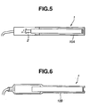
- one end of the optical transmission tube 1 is fixedly secured to a tubular joint member 20 with an adhesive or by cramping.
- the light source 2 in the form of LED is received in the joint member 20 and integrally coupled to the end face of the optical transmission tube 1.
- the light source 2 is electrically connected to the drive means 3 by a cord 30 with an insulating coat of rubber, vinyl resin or polyethylene.
- a cord 30 with an insulating coat of rubber, vinyl resin or polyethylene.
- the joint member 20 is filled with a potting material 21 such as an epoxy resin or silicone rubber for preventing entry of water, water vapor, combustible gas or liquid.
- the cord 30 may be inserted in a flexible sheath of metal or resin or a rubber or plastic pipe for protection or water-proofness.
- the structure of the optical transmission tube may be modified.
- the tube 1 may be inserted into a transparent resin pipe 10A for protection purpose.
- the tube 1 and the joint member 20 may be enclosed with a transparent heat shrinkable tubing 10B which is heat shrunk into tight fit for protecting the tube 1 and providing a seal over the entire structure.
- a light reflective layer 14 may formed on a (one side) portion of the outer surface of the optical transmission tube 1, for example, by attaching a reflective tape strip having a metal material such as stainless steel, gold or silver evaporated, sputtered or plated thereon, applying a reflective coating, attaching a metal foil, applying reflecting particles such as titanium oxide, or attaching a pigmented vinyl tape.
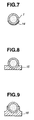
- a securing channel 15 or 16 may be attached to a (one side) portion of the outer surface of the optical transmission tube 1 as shown in FIGS. 8 and 9. If desired, the channel 15 or 16 is further given a reflecting function so that the channel may serve as a reflective protective layer.
- the channel 15 or 16 is usually formed of metal materials such as aluminum and stainless steel or plastic or elastomer materials loaded with highly reflective fine particles.
- the drive means 3 for supplying electricity to the light source 2 includes a power supply (e.g., a battery, solar battery or DC/AC power supply) and an electric circuit (including resistors, transistors, constant current diodes, etc., for example) for converting the power into direct current for operating the LED.
- a power supply e.g., a battery, solar battery or DC/AC power supply
- an electric circuit including resistors, transistors, constant current diodes, etc., for example
- the solar battery or secondary battery may be incorporated in the drive means 3 or externally connected to the drive means 3.
- a suitable sealant is applied where the cord 30 is extended from the drive means 3, for providing water-proofness.
- the linear illuminant system of the invention is of the construction comprising a light transmission tube prepared according to the invention, a light source coupled to at least one end of the light transmission tube in a water-proof manner, and a drive means for operating the light source, wherein the light transmission tube is constructed such that when light emitted from the light source is transmitted by the light transmission tube, light emerges from a longitudinal side of the light transmission tube.
- the light source is integrally coupled to the optical transmission tube in a water-proof manner so that the optical transmission tube and the light source may be disposed outdoor or in water, separately from the drive means.
- the linear illuminant system can be advantageously used in water, at places where rain or snow reaches, or in an environment with the risk of explosion.
- the system requires only a low electric power to produce sufficient side light emergence.
- the system is compact, and few restrictions are imposed on its installation site.
- a core-forming solution was prepared by mixing 60 parts by weight of methyl methacrylate (MMA), 40 parts by weight of lauryl methacrylate (LMA), and 0.05 part by weight of benzoyl peroxide (BPO) to form a monomer solution having a specific gravity of 0.92.
- MMA methyl methacrylate
- LMA lauryl methacrylate
- BPO benzoyl peroxide
- 100 parts by weight of the monomer solution were dispersed 0.15 part by weight of scattering particles which were silicone resin particles having a mean particle size of 7 ⁇ m and a specific gravity of 1.32 (commercially available from Toshiba K.K.) or polystyrene resin particles having a mean particle size of 10 ⁇ m and a specific gravity of 1.06 (commercially available from Sekisui Chemicals K.K.).
- This solution was fed into a FEP tube having an outer diameter of 6 mm and a length of 1.5 m, which was closed at both ends.
- the tube was rested on a horizontal table for 2 hours, allowing the particles to settle on a lower inner surface of the FEP tube.
- the tube was carefully transferred in a hot bath at 65°C so that the particle deposit might remain intact. In the hot bath, while a pressure of 3.5 kg/cm 2 was applied from the opposite ends of the tube, the monomer solution was polymerized and solidified for 3 hours.
- the optical transmission tube was tested by coupling a halogen lamp of 20 W as the light source with the tube so that light entered the tube from one end face. Light emerged from the tube along an elongated area of the other side surface of the tube opposed to the reflecting layer. The luminance of light was measured on the other side of the tube, using a colorimeter CS100 (Minolta K.K.). Measurement was made along the length of the tube at distances of 10 cm, 20 cm, 30 cm and 40 cm from the light incident end face of the tube. The results are shown in Table 1.
- an optical transmission tube was similarly prepared by filling the FEP tube with the monomer solution free of the particles and polymerizing the monomer solution.
- the tube was similarly measured for side luminance. The results are shown in Table 1. Dispersed particles Side luminance (cd/m 2 ) at a distance from the incident end Type Amount (pbw) 10 cm 20 cm 30 cm 40 cm Comparative Example - 0 65 19 12 11 Example Polystyrene particles 0.15 620 410 310 205 Silicone particles 0.15 613 422 380 265
- the tubes having a reflecting layer formed therein as a result of addition of scattering particles to a monomer solution allow light to emerge from the side surface at a higher luminance.
- the luminance is kept high even at distances remote from the light source, that is, the luminance distribution has a gentle slope.
- the optical transmission tube prepared as in Example 1 was measured for side luminance using a red LED lamp light source (applied voltage 2V, current 20 mA, 0.04 W). The results are shown in Table 2.
- a reflective tape (adhesive tape) of vinyl chloride resin loaded with a white pigment was attached to the one side surface of the cladding of the tube to surround the reflecting layer. This tube was also measured for side luminance, with the results shown in Table 2. Dispersed particles Side luminance (cd/m 2 ) at a distance from the incident end Type Amount (pbw) 5 cm 12 cm 20 cm Comparative Example - 0 3.3 1.0 0.4 Example Silicone particles 0.5 10.2 10.0 9.6 Silicone particles+ reflective tape 0.5 16.8 16.5 16
- a multi-color extruder having three screw sections and capable of co-extruding three materials was used.
- the core material used is shown in Table 3, the cladding material used was an acrylic polymer, and the reflecting material used was the same as the cladding material in which 15% by weight of titanium oxide was dispersed.
- the core material, cladding material, and reflecting material were simultaneously fed into the extruder from its inlet and extruded through concentric dies.
- the core material was extruded into a cylindrical rod having a diameter of 6 mm.
- the reflecting material was extruded into an axially extending strip having a transverse width of about 1.5 mm and a radial thickness of 0.03 to 0.02 mm on the outer surface of the cylindrical rod, the strip serving as a white reflecting layer.
- the cladding material was extruded into a tubular cladding enclosing the rod and the strip and having an outer diameter of 6.5 mm. There was obtained a cylindrical light tube.
- the optical transmission tubes prepared as in Example 3 were measured for side luminance using a red LED lamp light source (applied voltage 2V, current 20 mA, 0.04 W). The results are shown in Table 4. Core Side luminance (cd/m 2 ) at a distance from the incident end 5 cm 12 cm 20 cm Comparative Example Acrylic polymer 3.3 1.0 0.4 Example Polystyrene 9.7 9.0 8.5 Polycarbonate 9.2 8.6 8.1 Styrene-acrylate copolymer 8.6 7.8 7.5
- Example 3 The optical transmission tubes obtained in Example 3 were examined for the presence or absence of air between the layers and separation between the layers before and after a thermal shock test of rapidly cooling from 70°C to -30°C and then rapidly heating from -30°C to 70°C. Visual observation was made by passing light through the tubes.
- the optical transmission tube used herein was the tube of 30 cm long having a reflecting layer of silicone resin particles obtained in Example 1.
- a mirror finished stainless steel disc having a thickness of 1 mm and a diameter of 6 mm was joined to one end face of the tube with a clear epoxy adhesive as a reflecting plate.
- a green light emitting LED NSPG50 (by Nichia Chemical K.K.) was coupled to the other end face of the tube using an aluminum joint. Lead conductors were soldered to terminals of the LED while the connection zone was covered with a silicone rubber adhesive to provide a water-proof seal.
- a linear illuminant element (Example 6A) was constructed in this way.
- a comparative linear illuminant element was similarly constructed using the tube of Comparative Example in Example 1.
- Example 6A A current flow of 20 mA was conducted from a power supply to the LED whereby light emerged from the side area of the tube.
- the tube was measured for side luminance as in Example 1. Measurement was made along the length of the tube at distances of 50 mm, 150 mm, and 250 mm from the light incident end face of the tube. The results are shown in Table 5.
- the element of Example 6A produced a higher luminance than the comparative element.
- the power consumption was 0.06 W.
- the linear illuminant element was immersed in water for 6 months. Even after water immersion, the element could be operated to provide the same light emission as the initial element without current leakage and other problems.
- a linear illuminant element (Example 6B) was similarly constructed except that a channel as shown at 15 or 16 in FIG. 8 or 9 was formed from a highly reflective resin Banlite LD-1000R (Teijin K.K.) and the optical transmission tube was fitted into the channel. The channel itself was reflective. The tube was measured for side luminance as in Example 1, with the results shown in Table 5. Side luminance (cd/m 2 ) at a distance from the incident end 50 mm 150 mm 250 mm Example 6A 120 100 100 Example 6B 200 180 175 Comparative Example 20 10 10 10
- the tube of Example 6B having the reflective protective layer 14 in the form of a channel produced the highest side luminance
- the tube of Example 6A having the reflecting layer 13 produced a high side luminance
- the tube of Comparative Example without the reflecting layer 13 and the reflective protective layer 14 produced the lowest side luminance.
- the optical transmission tube 1 of the linear illuminant system is extended along the peripheral sides of a sign board 4.
- the sign board with such an illuminant molding contributes to safety driving at night.
- the optical transmission tubes 1 are attached to a side wall 5 of a tunnel.
- Equivalent objects include underground passages, corridors in buildings and hospitals, and emergency paths in public facilities such as theaters and halls.
- a commercial power supply may be used as the drive means for the light source.
- a provision is made such that upon a power failure, the light source can be driven by a battery.
- the LED used as the light source is expected to provide a far longer time of operation even when operated by a battery.
- the linearity of light emission instructs a safe smooth guide to people because the guidance path is ascertainable by an instant look.
- the optical transmission tubes 1 are extended along the upper edges of upright walls 6 of a stairway for preventing an accident by misstep at night.
- the tubes When the tubes are attached to an emergency stairway, the stairway can be readily ascertained upon emergency at night, contributing to safe evacuation guidance.
- FIG. 13 shows a segmented display panel 4' for indicating the maximum speed. For each digit, seven tubes are combined such that selected ones may be operated while the remaining ones are extinct. This enables variable indication of the speed limit. By increasing the number of segments, a character or modified display is possible.
- the optical transmission tube 1 is extended along the side of a vehicle interior 8A for providing indirect illumination.
- the optical transmission tube 1 is attached to a lower portion of the inner wall of a door 8B, serving as a foot light.
- the optical transmission tubes 1 are attached to the rear side 8C of a vehicle, serving as side lights.
- the optical transmission tube 1 is extended along the sides of a triangular emergency stop sign 9 which is used to inform the following drivers of the emergency stop of the car on the road.
- the linear illuminant element or system of the invention may find many other applications including (1) luminous nameplates, (2) guide poles used at night work, (3) luminous sticks, (4) luminous swords as sporting gears and toys, (5) warning lights suspended from tent ropes for warning against stumbling at night, (6) displays in aquariums, (7) course indicators and decorative lights in pools, (8) buoys, piers, banks and marine hoses (for providing improved visibility), (9) crossing gates, and (10) safety displays providing linear luminous bands for indicating crossing stop lines and the height limit of overhead beams or parking inlets.
Landscapes
- Physics & Mathematics (AREA)
- Engineering & Computer Science (AREA)
- Mechanical Engineering (AREA)
- General Physics & Mathematics (AREA)
- Optics & Photonics (AREA)
- Light Guides In General And Applications Therefor (AREA)
- Extrusion Moulding Of Plastics Or The Like (AREA)
- Non-Portable Lighting Devices Or Systems Thereof (AREA)
Claims (6)
- Un procédé de préparation d'un tube de transmission optique (1) utilisant une extrudeuse trois couleurs ayant trois sections de vis, comprenant les étapes consistant à:en formant ainsi le tube de transmission optique ayant la couche réfléchissante en forme de bande (13) s'étendant entre le revêtement (11) et le noyau (12) et longitudinalement au revêtement afin de former une structure stratifiée.(a) amener simultanément dans l'extrudeuse une matière de noyau, une matière de revêtement et une matière réfléchissante chargée d'une pigment blanc ou d'un agent de dispersion;(b) extruder la matière de noyau en un noyau cylindrique (12);(c) extruder la matière réfléchissante en une couche réfléchissante en forme de bande (13) sur la surface externe du noyau cylindrique (12); et(d) extruder la matière de revêtement en un revêtement tubulaire (11) entourant le noyau et la bande réfléchissante,
- Un procédé selon la revendication 1, comprenant en outre l'étape consistant à:(a) former une couche protectrice réfléchissante (14) sur une zone de la surface externe dudit revêtement (11) entourant la couche réfléchissante (13).
- Un procédé selon la revendication 1 ou la revendication 2 dans lequel ledit revêtement (11) est réalisé en polymère (meth)acrylique.
- Un procédé selon l'une quelconque des revendications précédentes dans lequel ledit noyau (12) est réalisé en polystyrène, en polycarbonate ou en un copolymère de styrène-(meth)acrylate.
- Un procédé selon l'une quelconque des revendications précédentes, dans lequel ladite couche réfléchissante (13) est réalisée en un polymère méthacrylique chargé d'un pigment blanc ou d'un agent de dispersion.
- Une système d'éclairage linéaire comprenant:un tube de transmission optique (1) pouvant être obtenu par le procédé de l'une quelconque des revendications 1 à 5 ;une source de lumière (2) accouplée d'une manière étanche à l'eau à au moins une extrémité dudit tube de transmission optique (1) ; etun moyen de commande (3) pour actionner la source de lumière (2).
Applications Claiming Priority (5)
| Application Number | Priority Date | Filing Date | Title |
|---|---|---|---|
| JP12167697 | 1997-04-24 | ||
| JP12167697 | 1997-04-24 | ||
| JP24189297 | 1997-08-22 | ||
| JP9241892A JPH1166928A (ja) | 1997-08-22 | 1997-08-22 | 線状発光体 |
| EP98303168A EP0874191B1 (fr) | 1997-04-24 | 1998-04-24 | Tube à transmission optique, procédé de sa fabrication et système d'éclairage linéaire |
Related Parent Applications (1)
| Application Number | Title | Priority Date | Filing Date |
|---|---|---|---|
| EP98303168A Division EP0874191B1 (fr) | 1997-04-24 | 1998-04-24 | Tube à transmission optique, procédé de sa fabrication et système d'éclairage linéaire |
Publications (3)
| Publication Number | Publication Date |
|---|---|
| EP1221628A2 EP1221628A2 (fr) | 2002-07-10 |
| EP1221628A3 EP1221628A3 (fr) | 2002-07-24 |
| EP1221628B1 true EP1221628B1 (fr) | 2005-10-26 |
Family
ID=26458973
Family Applications (2)
| Application Number | Title | Priority Date | Filing Date |
|---|---|---|---|
| EP98303168A Expired - Lifetime EP0874191B1 (fr) | 1997-04-24 | 1998-04-24 | Tube à transmission optique, procédé de sa fabrication et système d'éclairage linéaire |
| EP02005409A Expired - Lifetime EP1221628B1 (fr) | 1997-04-24 | 1998-04-24 | Tube à transmission optique, procédé de sa fabrication et système d'éclairage linéaire |
Family Applications Before (1)
| Application Number | Title | Priority Date | Filing Date |
|---|---|---|---|
| EP98303168A Expired - Lifetime EP0874191B1 (fr) | 1997-04-24 | 1998-04-24 | Tube à transmission optique, procédé de sa fabrication et système d'éclairage linéaire |
Country Status (3)
| Country | Link |
|---|---|
| US (1) | US5982969A (fr) |
| EP (2) | EP0874191B1 (fr) |
| DE (2) | DE69832106T2 (fr) |
Families Citing this family (152)
| Publication number | Priority date | Publication date | Assignee | Title |
|---|---|---|---|---|
| DE10347053A1 (de) * | 2003-10-07 | 2005-05-04 | Hella Kgaa Hueck & Co | Innenleuchte für Fahrzeuge |
| US6185356B1 (en) * | 1995-06-27 | 2001-02-06 | Lumitex, Inc. | Protective cover for a lighting device |
| US6739744B2 (en) * | 1997-07-02 | 2004-05-25 | Lumitex, Inc. | Light delivery systems and applications thereof |
| US7306559B2 (en) * | 1997-07-02 | 2007-12-11 | Lumitex, Inc. | Illuminated surgical retractor |
| US20050171408A1 (en) * | 1997-07-02 | 2005-08-04 | Parker Jeffery R. | Light delivery systems and applications thereof |
| US6591049B2 (en) | 1997-07-02 | 2003-07-08 | Lumitex, Inc. | Light delivery systems and applications thereof |
| US20030133292A1 (en) | 1999-11-18 | 2003-07-17 | Mueller George G. | Methods and apparatus for generating and modulating white light illumination conditions |
| US7014336B1 (en) | 1999-11-18 | 2006-03-21 | Color Kinetics Incorporated | Systems and methods for generating and modulating illumination conditions |
| US7161313B2 (en) * | 1997-08-26 | 2007-01-09 | Color Kinetics Incorporated | Light emitting diode based products |
| US6863428B2 (en) * | 1997-10-24 | 2005-03-08 | 3M Innovative Properties Company | Light guide illumination device appearing uniform in brightness along its length |
| GB2336660B (en) * | 1998-04-20 | 2002-03-06 | Bridgestone Corp | Light transmission tubes and methods for manufacturing the light transmission tubes |
| JPH11326644A (ja) * | 1998-05-20 | 1999-11-26 | Bridgestone Corp | 光伝送チューブ及びその製造方法 |
| GB9820854D0 (en) * | 1998-09-24 | 1998-11-18 | Lifor Limited | Fibre optic based directional way finding apparatus and method |
| US6519401B1 (en) | 1998-10-28 | 2003-02-11 | 3M Innovative Properties Company | Light fibers and methods for producing the same |
| US6236797B1 (en) * | 1998-11-05 | 2001-05-22 | Bridgestone Corporation | Light transmitting tube |
| DE60026689T2 (de) * | 1999-01-14 | 2006-11-23 | Federal-Mogul Corp., Southfield | Beleuchtungsanlagen für kraftfahrzeuge |
| DE10083893T1 (de) * | 1999-01-28 | 2002-06-06 | Bridgestone Corp | Lineares Beleuchtungssystem, Verfahren zur Herstellung desselben und Abtastvorrichtung |
| US6152586A (en) * | 1999-01-28 | 2000-11-28 | Transmatic, Inc. | Cargo area lighting system for trucks |
| US6398778B1 (en) | 1999-06-18 | 2002-06-04 | Photonics Research Ontario | Optical fiber diffuser |
| CA2375267A1 (fr) * | 1999-06-18 | 2000-12-28 | Xijia Gu | Diffuseur a fibre optique |
| DE60009299T2 (de) * | 1999-07-16 | 2004-08-05 | Bridgestone Corp. | Aufnahme für eine anzeige in einem kraftfahrzeug |
| DE19940849B4 (de) * | 1999-08-27 | 2013-01-03 | Lisa Dräxlmaier GmbH | Lichtwellenleiter |
| US6577794B1 (en) * | 1999-09-27 | 2003-06-10 | Robert M. Currie | Compound optical and electrical conductors, and connectors therefor |
| US20020176259A1 (en) | 1999-11-18 | 2002-11-28 | Ducharme Alfred D. | Systems and methods for converting illumination |
| US6603243B2 (en) | 2000-03-06 | 2003-08-05 | Teledyne Technologies Incorporated | LED light source with field-of-view-controlling optics |
| CA2401459A1 (fr) | 2000-03-06 | 2001-09-13 | Teledyne Lighting And Display Products, Inc. | Appareil d'eclairage dote d'une couche a points quantiques |
| US6501218B1 (en) * | 2000-06-12 | 2002-12-31 | General Electric Company | Outdoor electroluminescent display devices |
| US6450677B1 (en) | 2000-09-21 | 2002-09-17 | Robert M. Knauer | Fiberoptic lighting system |
| US6637924B2 (en) * | 2000-11-15 | 2003-10-28 | Teledyne Lighting And Display Products, Inc. | Strip lighting apparatus and method |
| US6634779B2 (en) * | 2001-01-09 | 2003-10-21 | Rpm Optoelectronics, Inc. | Method and apparatus for linear led lighting |
| US20020159741A1 (en) * | 2001-02-26 | 2002-10-31 | Graves Stephen M. | Optical transmission tube and applications thereof |
| AU2002308415B2 (en) * | 2001-05-22 | 2006-03-02 | Poly Optics Australia Pty Ltd | Side scattering polymer light guide and method of manufacture |
| AUPR518801A0 (en) * | 2001-05-22 | 2001-06-14 | Poly Optics Australia Pty Ltd | Side scattering fibre-optic and method of manufacturing a side scattering fibre-optic |
| US6784603B2 (en) * | 2001-07-20 | 2004-08-31 | Teledyne Lighting And Display Products, Inc. | Fluorescent lighting apparatus |
| US8388164B2 (en) * | 2005-05-17 | 2013-03-05 | Michael Waters | Hands-Free lighting devices |
| US6769799B2 (en) | 2002-03-12 | 2004-08-03 | Tyco Electronics Canada | Apparatus, methods and articles of manufacture for a co-extruded light pipe |
| GB0211351D0 (en) * | 2002-05-16 | 2002-06-26 | Lasota Andrew S | Illuminable display device |
| AU2002951256A0 (en) * | 2002-09-06 | 2002-09-19 | Poly Optics Australia Pty Ltd | Improvements in side-scattering light guides |
| JP3753117B2 (ja) * | 2002-09-17 | 2006-03-08 | ヤマハ株式会社 | 電子機器およびその表示器取付方法 |
| AU2003269822A1 (en) * | 2002-10-21 | 2004-05-13 | Plastic Inventions And Patents, Inc. | Compound optical and electrical conductors, and connectors therefor |
| US6834988B2 (en) * | 2002-11-05 | 2004-12-28 | General Binding Corporation | Enhanced thermal indicator light system and method for the use thereof |
| WO2004070262A2 (fr) * | 2003-02-04 | 2004-08-19 | Ilight Technologies, Inc. | Dispositif d'eclairage flexible pour simulation d'eclairage au neon |
| US7164819B2 (en) * | 2003-03-10 | 2007-01-16 | Fiberstars, Inc. | Side-light extraction by light pipe-surface alteration and light-extraction devices extending radially beyond the outer cladding |
| US7194184B2 (en) * | 2003-03-10 | 2007-03-20 | Fiberstars Incorporated | Light pipe with side-light extraction |
| US6910795B2 (en) * | 2003-04-18 | 2005-06-28 | Tyco Electronics Canada, Ltd. | Overmolded low voltage lamp assembly |
| WO2005017966A2 (fr) * | 2003-08-04 | 2005-02-24 | Advanced Illumination Technologies, Llc | Forme electroluminescente emettant un halo |
| US20050068790A1 (en) * | 2003-09-25 | 2005-03-31 | Love David A. | Light emitting diode glow tube |
| US20050084229A1 (en) * | 2003-10-20 | 2005-04-21 | Victor Babbitt | Light insertion and dispersion system |
| US20050094415A1 (en) * | 2003-10-29 | 2005-05-05 | Bor-Dong Cheng | Body molding for car |
| IL158952A0 (en) * | 2003-11-19 | 2004-05-12 | Elam Electroluminescent Ind Lt | Electroluminescent flexible modular light source |
| GB0329205D0 (en) * | 2003-12-17 | 2004-01-21 | Graham Morton | An illumination device |
| US7097291B2 (en) | 2004-01-21 | 2006-08-29 | Silverbrook Research Pty Ltd | Inkjet printer cartridge with ink refill port having multiple ink couplings |
| US7083273B2 (en) * | 2004-01-21 | 2006-08-01 | Silverbrook Research Pty Ltd | Inkjet printer cartridge with uniform compressed air distribution |
| US7198352B2 (en) * | 2004-01-21 | 2007-04-03 | Kia Silverbrook | Inkjet printer cradle with cartridge stabilizing mechanism |
| US7328985B2 (en) * | 2004-01-21 | 2008-02-12 | Silverbrook Research Pty Ltd | Inkjet printer cartridge refill dispenser with security mechanism |
| US7441865B2 (en) | 2004-01-21 | 2008-10-28 | Silverbrook Research Pty Ltd | Printhead chip having longitudinal ink supply channels |
| US7374355B2 (en) | 2004-01-21 | 2008-05-20 | Silverbrook Research Pty Ltd | Inkjet printer cradle for receiving a pagewidth printhead cartridge |
| US7524016B2 (en) * | 2004-01-21 | 2009-04-28 | Silverbrook Research Pty Ltd | Cartridge unit having negatively pressurized ink storage |
| US7367647B2 (en) * | 2004-01-21 | 2008-05-06 | Silverbrook Research Pty Ltd | Pagewidth inkjet printer cartridge with ink delivery member |
| US7645025B2 (en) | 2004-01-21 | 2010-01-12 | Silverbrook Research Pty Ltd | Inkjet printer cartridge with two printhead integrated circuits |
| US7469989B2 (en) | 2004-01-21 | 2008-12-30 | Silverbrook Research Pty Ltd | Printhead chip having longitudinal ink supply channels interrupted by transverse bridges |
| US20050157128A1 (en) * | 2004-01-21 | 2005-07-21 | Silverbrook Research Pty Ltd | Pagewidth inkjet printer cartridge with end electrical connectors |
| US7303255B2 (en) | 2004-01-21 | 2007-12-04 | Silverbrook Research Pty Ltd | Inkjet printer cartridge with a compressed air port |
| US7448734B2 (en) * | 2004-01-21 | 2008-11-11 | Silverbrook Research Pty Ltd | Inkjet printer cartridge with pagewidth printhead |
| US20050157000A1 (en) * | 2004-01-21 | 2005-07-21 | Silverbrook Research Pty Ltd | Inkjet printer cradle with end data and power contacts |
| US20050157125A1 (en) * | 2004-01-21 | 2005-07-21 | Silverbrook Research Pty Ltd | Inkjet printer cartridge with integral shield |
| US7731327B2 (en) | 2004-01-21 | 2010-06-08 | Silverbrook Research Pty Ltd | Desktop printer with cartridge incorporating printhead integrated circuit |
| US20050157112A1 (en) * | 2004-01-21 | 2005-07-21 | Silverbrook Research Pty Ltd | Inkjet printer cradle with shaped recess for receiving a printer cartridge |
| US7287846B2 (en) * | 2004-01-21 | 2007-10-30 | Silverbrook Research Pty Ltd | Inkjet printer cartridge with combined blotter |
| US7360868B2 (en) * | 2004-01-21 | 2008-04-22 | Silverbrook Research Pty Ltd | Inkjet printer cartridge with infrared ink delivery capabilities |
| US7364264B2 (en) * | 2004-01-21 | 2008-04-29 | Silverbrook Research Pty Ltd | Inkjet printer cradle with single drive motor performing multiple functions |
| DE102004015293B3 (de) * | 2004-03-29 | 2005-12-08 | Albis Plastic Gmbh | Beleuchtbare Informationseinheit für technische Geräte oder Maschinen und deren Verwendung |
| EP1735563A4 (fr) * | 2004-04-16 | 2007-11-28 | Fiberstars Inc | Luminaire a bon rendement a extraction de lumiere lateralement dirigee |
| US20050244610A1 (en) * | 2004-04-29 | 2005-11-03 | Visteon Global Technologies, Inc. | Injection molding of components for vehicles |
| US7273300B2 (en) * | 2004-08-06 | 2007-09-25 | Lumination Llc | Curvilinear LED light source |
| US20060044824A1 (en) * | 2004-08-24 | 2006-03-02 | Yung-Hwa Chen | Soft warning strip |
| CA2579196C (fr) * | 2004-09-10 | 2010-06-22 | Color Kinetics Incorporated | Procede et appareil de gestion de l'eclairage par zones |
| US7389020B2 (en) * | 2005-01-28 | 2008-06-17 | Intier Automotive Inc. | Light pipe assembly |
| US7549783B2 (en) * | 2005-04-18 | 2009-06-23 | Energy Focus, Inc. | Efficient luminaire with directional side-light extraction |
| US9526292B2 (en) | 2005-05-17 | 2016-12-27 | Michael Waters | Power modules and headgear |
| JP2007022325A (ja) * | 2005-07-15 | 2007-02-01 | Fujikura Ltd | 車両用ドアの照明装置 |
| US8409088B2 (en) | 2006-01-18 | 2013-04-02 | Invuity, Inc. | Retractor illumination system |
| US7374313B2 (en) * | 2006-03-02 | 2008-05-20 | Energy Focus, Inc. | Luminaire with improved lateral illuminance control |
| ATE434814T1 (de) * | 2006-03-08 | 2009-07-15 | Fiat Ricerche | Modulare beleuchtete anzeige |
| US7588342B2 (en) * | 2006-04-24 | 2009-09-15 | Energy Focus, Inc. | Lighted refrigerated display case with remote light source |
| US8047987B2 (en) | 2006-05-26 | 2011-11-01 | Invuity, Inc. | Blade insert illuminator |
| DE102006035521B4 (de) * | 2006-07-31 | 2014-09-04 | Audi Ag | Kraftfahrzeug |
| GB0625761D0 (en) * | 2006-12-22 | 2007-02-07 | Graham Morton | A lighting device |
| US20090027914A1 (en) * | 2007-07-26 | 2009-01-29 | Chia-Yeh Wu | Structure for a center high mounted stop lamp |
| JP5443677B2 (ja) * | 2007-09-21 | 2014-03-19 | オリンパスメディカルシステムズ株式会社 | 照明装置および内視鏡 |
| US8088066B2 (en) | 2007-10-24 | 2012-01-03 | Invuity, Inc. | Blade insert illuminator |
| WO2009074510A1 (fr) | 2007-12-10 | 2009-06-18 | Volkswagen Ag | Feu de véhicule et procédé de fabrication d'un élément transparent pour un feu de véhicule |
| EP2238386B1 (fr) | 2007-12-18 | 2014-04-09 | Michael Waters | Casque éclairé |
| US8491145B2 (en) | 2007-12-18 | 2013-07-23 | Waters Industries, Inc. | Illuminated headgear having switch devices and packaging therefor |
| US8757831B2 (en) | 2007-12-18 | 2014-06-24 | Michael Waters | Headgear having an electrical device and power source mounted thereto |
| WO2009083039A1 (fr) * | 2008-01-02 | 2009-07-09 | Illinois Tool Works Inc | Dispositif d'éclairage pour un dispositif de stockage réfrigérant et dispositif de stockage réfrigérant comprenant un tel dispositif d'éclairage |
| ES2730703T3 (es) * | 2008-02-14 | 2019-11-12 | Schott Ag | Fibras con índice de nivel de emisión lateral, método de producción y empleo de las mismas |
| US11382711B2 (en) | 2008-08-13 | 2022-07-12 | Invuity, Inc. | Cyclo olefin polymer and copolymer medical devices |
| EP2401546B1 (fr) | 2009-02-27 | 2016-05-18 | Michael Waters | Chapeau éclairé |
| US8998472B2 (en) * | 2009-05-04 | 2015-04-07 | Walter A Johanson | Liquid filled light guide containing voids within the walls |
| US9800017B1 (en) | 2009-05-29 | 2017-10-24 | Soraa Laser Diode, Inc. | Laser device and method for a vehicle |
| US10108079B2 (en) | 2009-05-29 | 2018-10-23 | Soraa Laser Diode, Inc. | Laser light source for a vehicle |
| US8218938B2 (en) * | 2009-07-02 | 2012-07-10 | Chang-Hsien Ho | Light guide strip structure |
| US20110090710A1 (en) * | 2009-10-15 | 2011-04-21 | Edmund Joseph Kelly | High Efficiency Light Pipe |
| CN105974513B (zh) | 2009-11-20 | 2022-10-14 | 康宁股份有限公司 | 具有侧面发光的光学光子纤维的照明系统及其制造方法 |
| CN202975580U (zh) | 2010-04-30 | 2013-06-05 | 迈克尔·沃特斯 | 头部装备和安装在帽子上的摄像机装置 |
| US8540409B2 (en) * | 2010-05-27 | 2013-09-24 | Osram Opto Semiconductors Gmbh | Light guide and semiconductor luminaire |
| DE102010025350A1 (de) * | 2010-06-28 | 2011-11-03 | Audi Ag | Beleuchtungsvorrichtung |
| JP5561153B2 (ja) * | 2010-12-27 | 2014-07-30 | ティアック株式会社 | 電子機器および導光レンズの取り付け方法 |
| CA2794370A1 (fr) | 2011-11-04 | 2013-05-04 | Michael Waters | Chapeau a fonction de desactivation automatique pour dispositifs electriques |
| US9376333B2 (en) * | 2011-12-09 | 2016-06-28 | Mag Aerospace Industries, Llc | Inline UV LED water disinfection and heating |
| US9568173B2 (en) | 2011-12-23 | 2017-02-14 | Michael Waters | Lighted hat |
| US9526287B2 (en) | 2011-12-23 | 2016-12-27 | Michael Waters | Lighted hat |
| US9609902B2 (en) | 2011-12-23 | 2017-04-04 | Michael Waters | Headgear having a camera device |
| US8620123B2 (en) | 2012-02-13 | 2013-12-31 | Corning Cable Systems Llc | Visual tracer system for fiber optic cable |
| DE102012019074A1 (de) * | 2012-09-27 | 2014-03-27 | Airbus Operations Gmbh | Mobiles Leuchtsystem |
| WO2014100477A1 (fr) | 2012-12-19 | 2014-06-26 | Michael Waters | Chapeau solaire illuminé |
| US20140218955A1 (en) * | 2013-02-01 | 2014-08-07 | Scott Lee | Illuminated moldings with integrated control |
| US9254785B2 (en) * | 2013-02-14 | 2016-02-09 | Ford Global Technologies, Llc | Extruded light pipe carrier |
| GB2511139B (en) | 2013-02-26 | 2015-01-14 | Visteon Global Tech Inc | Strip lighting device |
| WO2014144507A1 (fr) | 2013-03-15 | 2014-09-18 | Michael Waters | Couvre-chef lumineux |
| WO2014186589A1 (fr) * | 2013-05-15 | 2014-11-20 | Johnson Controls Technology Company | Composant d'habitacle de véhicule muni d'une bande éclairée |
| US20140363134A1 (en) * | 2013-06-10 | 2014-12-11 | Corning Optical Communications LLC | Optical fiber cable assembly comprising optical tracer fiber |
| US9429731B2 (en) | 2013-08-12 | 2016-08-30 | Corning Optical Communications LLC | Optical fiber cable assembly comprising optical tracer fiber |
| US9643350B2 (en) | 2013-09-11 | 2017-05-09 | Ford Global Technologies, Llc | Wet-out prevent method using laminate for injection molding process |
| TW201525044A (zh) * | 2013-12-16 | 2015-07-01 | Genesis Photonics Inc | 發光裝置及波長轉換層的製作方法 |
| JP6287421B2 (ja) | 2014-03-24 | 2018-03-07 | 株式会社デンソー | ライトガイド部材、ライトガイド部材用のアタッチメント、イルミネーション装置 |
| JP6303728B2 (ja) * | 2014-03-31 | 2018-04-04 | 東芝ライテック株式会社 | ランプ |
| USD770143S1 (en) | 2014-05-23 | 2016-11-01 | Michael Waters | Beanie with means for illumination |
| KR20170015458A (ko) * | 2014-06-06 | 2017-02-08 | 케이와 인코포레이티드 | 에지 라이트형 백라이트 유닛 및 반사 테이프 부재 |
| US10379309B2 (en) | 2014-11-18 | 2019-08-13 | Corning Optical Communications LLC | Traceable optical fiber cable and filtered viewing device for enhanced traceability |
| US10228526B2 (en) | 2015-03-31 | 2019-03-12 | Corning Optical Communications LLC | Traceable cable with side-emitting optical fiber and method of forming the same |
| US10101553B2 (en) | 2015-05-20 | 2018-10-16 | Corning Optical Communications LLC | Traceable cable with side-emitting optical fiber and method of forming the same |
| EP3325876A1 (fr) | 2015-07-17 | 2018-05-30 | Corning Optical Communications LLC | Systèmes et procédés pour câbles traçables |
| EP3326014A1 (fr) | 2015-07-17 | 2018-05-30 | Corning Optical Communications LLC | Systèmes et procédés pour câbles de traçage, et câbles pour de tels systèmes et de tels procédés |
| US10938182B2 (en) | 2015-08-19 | 2021-03-02 | Soraa Laser Diode, Inc. | Specialized integrated light source using a laser diode |
| US10101545B2 (en) | 2015-10-30 | 2018-10-16 | Corning Optical Communications LLC | Traceable cable assembly and connector |
| US9986438B2 (en) | 2016-01-22 | 2018-05-29 | Microsoft Technology Licensing, Llc | Hierarchical spectrum coordination |
| CN109154702A (zh) | 2016-04-08 | 2019-01-04 | 康宁光电通信有限责任公司 | 可追踪端点电缆组件 |
| US10107983B2 (en) | 2016-04-29 | 2018-10-23 | Corning Optical Communications LLC | Preferential mode coupling for enhanced traceable patch cord performance |
| US10222560B2 (en) | 2016-12-21 | 2019-03-05 | Corning Research & Development Corporation | Traceable fiber optic cable assembly with fiber guide and tracing optical fibers for carrying light received from a light launch device |
| FR3061562B1 (fr) * | 2017-01-04 | 2019-08-02 | Valeo Vision | Dispositif de raccordement amovible pour un guide de lumiere et application dans un vehicule automobile, module a transmission optique pourvu du dispositif |
| US10234614B2 (en) | 2017-01-20 | 2019-03-19 | Corning Research & Development Corporation | Light source assemblies and systems and methods with mode homogenization |
| US10618222B2 (en) * | 2017-09-15 | 2020-04-14 | The Boeing Company | Systems and methods for additively manufacturing an object |
| US11421843B2 (en) | 2018-12-21 | 2022-08-23 | Kyocera Sld Laser, Inc. | Fiber-delivered laser-induced dynamic light system |
| US11239637B2 (en) | 2018-12-21 | 2022-02-01 | Kyocera Sld Laser, Inc. | Fiber delivered laser induced white light system |
| US12000552B2 (en) * | 2019-01-18 | 2024-06-04 | Kyocera Sld Laser, Inc. | Laser-based fiber-coupled white light system for a vehicle |
| US20210278584A1 (en) * | 2019-01-18 | 2021-09-09 | Kyocera Sld Laser, Inc. | Edge coupled fiber light |
| US11884202B2 (en) | 2019-01-18 | 2024-01-30 | Kyocera Sld Laser, Inc. | Laser-based fiber-coupled white light system |
| US10791783B1 (en) | 2019-05-16 | 2020-10-06 | Waters Industries, Inc. | Lighted headgear and accessories therefor |
| KR102234607B1 (ko) * | 2019-07-30 | 2021-04-01 | 주식회사 진흥강재 | 조류충돌저감용 방음판 구조 |
| EP4183631A1 (fr) * | 2021-11-18 | 2023-05-24 | Giovanni Storti | Dispositif de signalisation à fibre optique, notamment pour moyens de transport |
Citations (3)
| Publication number | Priority date | Publication date | Assignee | Title |
|---|---|---|---|---|
| US4666640A (en) * | 1986-02-13 | 1987-05-19 | Neefe Charles W | Method of making a spin cast gradient light absorbing contact lens |
| EP0800036A1 (fr) * | 1996-04-04 | 1997-10-08 | Hitachi Cable, Ltd. | Système lumineux |
| WO1998020279A1 (fr) * | 1996-11-07 | 1998-05-14 | Minnesota Mining And Manufacturing Company | Tiges d'illumination par amenee de lumiere |
Family Cites Families (5)
| Publication number | Priority date | Publication date | Assignee | Title |
|---|---|---|---|---|
| US4422719A (en) * | 1981-05-07 | 1983-12-27 | Space-Lyte International, Inc. | Optical distribution system including light guide |
| EP0131058B1 (fr) * | 1983-06-22 | 1988-01-27 | Mitsubishi Rayon Co., Ltd. | Assemblage de fibres optiques et procédé pour sa préparation |
| US4733332A (en) * | 1985-02-22 | 1988-03-22 | Agency Of Industrial Science And Technology | Illuminating device |
| US4806289A (en) * | 1987-01-16 | 1989-02-21 | The Dow Chemical Company | Method of making a hollow light pipe |
| US5799124A (en) * | 1996-05-15 | 1998-08-25 | Southeastern Univ. Research Assn., Inc. | Illuminating system and method for specialized and decorative lighting using liquid light guides |
-
1998
- 1998-04-24 US US09/065,604 patent/US5982969A/en not_active Expired - Fee Related
- 1998-04-24 EP EP98303168A patent/EP0874191B1/fr not_active Expired - Lifetime
- 1998-04-24 DE DE69832106T patent/DE69832106T2/de not_active Expired - Fee Related
- 1998-04-24 DE DE69807564T patent/DE69807564T2/de not_active Expired - Fee Related
- 1998-04-24 EP EP02005409A patent/EP1221628B1/fr not_active Expired - Lifetime
Patent Citations (3)
| Publication number | Priority date | Publication date | Assignee | Title |
|---|---|---|---|---|
| US4666640A (en) * | 1986-02-13 | 1987-05-19 | Neefe Charles W | Method of making a spin cast gradient light absorbing contact lens |
| EP0800036A1 (fr) * | 1996-04-04 | 1997-10-08 | Hitachi Cable, Ltd. | Système lumineux |
| WO1998020279A1 (fr) * | 1996-11-07 | 1998-05-14 | Minnesota Mining And Manufacturing Company | Tiges d'illumination par amenee de lumiere |
Also Published As
| Publication number | Publication date |
|---|---|
| EP0874191A3 (fr) | 1999-01-07 |
| DE69832106T2 (de) | 2006-07-20 |
| US5982969A (en) | 1999-11-09 |
| DE69807564T2 (de) | 2003-05-15 |
| DE69832106D1 (de) | 2005-12-01 |
| DE69807564D1 (de) | 2002-10-10 |
| EP1221628A3 (fr) | 2002-07-24 |
| EP0874191A2 (fr) | 1998-10-28 |
| EP0874191B1 (fr) | 2002-09-04 |
| EP1221628A2 (fr) | 2002-07-10 |
Similar Documents
| Publication | Publication Date | Title |
|---|---|---|
| EP1221628B1 (fr) | Tube à transmission optique, procédé de sa fabrication et système d'éclairage linéaire | |
| US6104857A (en) | Line glower | |
| JP2000131529A (ja) | 線状発光体 | |
| AU598079B2 (en) | Lighting apparatus and method | |
| AU616589B2 (en) | Improved linear optical conduits, systems and methods of manufacture | |
| US5333227A (en) | Optical waveguide hose | |
| US20050074216A1 (en) | Side-illumination type optical fiber | |
| US20010016105A1 (en) | Method of manufacturing light transmission tubes | |
| EP1125152B1 (fr) | Fibres optiques et leurs procedes de fabrication | |
| KR20030068188A (ko) | 측면 발광형 광섬유 | |
| US6563993B1 (en) | Light fiber and a method for producing the same | |
| AU762580B2 (en) | A light fiber and a method for producing the same | |
| JP2000222908A (ja) | 線状発光体の製造方法 | |
| JP2001032226A (ja) | 道路鋲 | |
| JPH1166919A (ja) | 駐車場若しくは駐機場用誘導装置 | |
| JP2001030978A (ja) | 灯浮標、棧橋及び堤防 | |
| JPH116918A (ja) | 光伝送チューブ及びその製造方法 | |
| JPH08246426A (ja) | 道路柵 | |
| JPH11148114A (ja) | 線状発光体による道路標識 | |
| JPH1159424A (ja) | 鉄道遮断機用照明装置 | |
| JP2000067621A (ja) | 浴室用照明装置 | |
| JP2000067622A (ja) | 浴室のステップ用照明装置 | |
| JP2000110123A (ja) | 発光式視線誘導装置及び防護柵 | |
| JP2001032227A (ja) | 道 路 | |
| JP2000067639A (ja) | 浴室用照明装置 |
Legal Events
| Date | Code | Title | Description |
|---|---|---|---|
| PUAI | Public reference made under article 153(3) epc to a published international application that has entered the european phase |
Free format text: ORIGINAL CODE: 0009012 |
|
| PUAL | Search report despatched |
Free format text: ORIGINAL CODE: 0009013 |
|
| AC | Divisional application: reference to earlier application |
Ref document number: 874191 Country of ref document: EP |
|
| AK | Designated contracting states |
Kind code of ref document: A2 Designated state(s): DE FR GB |
|
| AK | Designated contracting states |
Kind code of ref document: A3 Designated state(s): DE FR GB |
|
| RIN1 | Information on inventor provided before grant (corrected) |
Inventor name: TANUMA, ITSUO Inventor name: FUKUYAMA, HIROSHI Inventor name: TERAHAMA, TATSUO Inventor name: SUGIYAMA, HIDEO Inventor name: ISHIHARADA, MINORU Inventor name: MORIMURA, YASUHIRO Inventor name: SUGIMACHI, MASATO |
|
| 17P | Request for examination filed |
Effective date: 20020830 |
|
| AKX | Designation fees paid |
Designated state(s): DE FR GB |
|
| 17Q | First examination report despatched |
Effective date: 20030714 |
|
| GRAP | Despatch of communication of intention to grant a patent |
Free format text: ORIGINAL CODE: EPIDOSNIGR1 |
|
| GRAS | Grant fee paid |
Free format text: ORIGINAL CODE: EPIDOSNIGR3 |
|
| GRAA | (expected) grant |
Free format text: ORIGINAL CODE: 0009210 |
|
| AC | Divisional application: reference to earlier application |
Ref document number: 0874191 Country of ref document: EP Kind code of ref document: P |
|
| AK | Designated contracting states |
Kind code of ref document: B1 Designated state(s): DE FR GB |
|
| REG | Reference to a national code |
Ref country code: GB Ref legal event code: FG4D |
|
| REF | Corresponds to: |
Ref document number: 69832106 Country of ref document: DE Date of ref document: 20051201 Kind code of ref document: P |
|
| PGFP | Annual fee paid to national office [announced via postgrant information from national office to epo] |
Ref country code: GB Payment date: 20060320 Year of fee payment: 9 |
|
| PGFP | Annual fee paid to national office [announced via postgrant information from national office to epo] |
Ref country code: DE Payment date: 20060330 Year of fee payment: 9 |
|
| ET | Fr: translation filed | ||
| PLBE | No opposition filed within time limit |
Free format text: ORIGINAL CODE: 0009261 |
|
| STAA | Information on the status of an ep patent application or granted ep patent |
Free format text: STATUS: NO OPPOSITION FILED WITHIN TIME LIMIT |
|
| 26N | No opposition filed |
Effective date: 20060727 |
|
| GBPC | Gb: european patent ceased through non-payment of renewal fee |
Effective date: 20070424 |
|
| PG25 | Lapsed in a contracting state [announced via postgrant information from national office to epo] |
Ref country code: DE Free format text: LAPSE BECAUSE OF NON-PAYMENT OF DUE FEES Effective date: 20071101 |
|
| PG25 | Lapsed in a contracting state [announced via postgrant information from national office to epo] |
Ref country code: GB Free format text: LAPSE BECAUSE OF NON-PAYMENT OF DUE FEES Effective date: 20070424 |
|
| PGFP | Annual fee paid to national office [announced via postgrant information from national office to epo] |
Ref country code: FR Payment date: 20120504 Year of fee payment: 15 |
|
| REG | Reference to a national code |
Ref country code: FR Ref legal event code: ST Effective date: 20131231 |
|
| PG25 | Lapsed in a contracting state [announced via postgrant information from national office to epo] |
Ref country code: FR Free format text: LAPSE BECAUSE OF NON-PAYMENT OF DUE FEES Effective date: 20130430 |