EP1221516A2 - Verfahren und Vorrichtung zum Aufbringen von Dünnbettmörtel - Google Patents
Verfahren und Vorrichtung zum Aufbringen von Dünnbettmörtel Download PDFInfo
- Publication number
- EP1221516A2 EP1221516A2 EP01123713A EP01123713A EP1221516A2 EP 1221516 A2 EP1221516 A2 EP 1221516A2 EP 01123713 A EP01123713 A EP 01123713A EP 01123713 A EP01123713 A EP 01123713A EP 1221516 A2 EP1221516 A2 EP 1221516A2
- Authority
- EP
- European Patent Office
- Prior art keywords
- mortar
- conveyor belt
- stones
- mortar application
- carriage
- Prior art date
- Legal status (The legal status is an assumption and is not a legal conclusion. Google has not performed a legal analysis and makes no representation as to the accuracy of the status listed.)
- Granted
Links
Images


Classifications
-
- E—FIXED CONSTRUCTIONS
- E04—BUILDING
- E04G—SCAFFOLDING; FORMS; SHUTTERING; BUILDING IMPLEMENTS OR AIDS, OR THEIR USE; HANDLING BUILDING MATERIALS ON THE SITE; REPAIRING, BREAKING-UP OR OTHER WORK ON EXISTING BUILDINGS
- E04G21/00—Preparing, conveying, or working-up building materials or building elements in situ; Other devices or measures for constructional work
- E04G21/14—Conveying or assembling building elements
- E04G21/16—Tools or apparatus
- E04G21/20—Tools or apparatus for applying mortar
-
- E—FIXED CONSTRUCTIONS
- E04—BUILDING
- E04G—SCAFFOLDING; FORMS; SHUTTERING; BUILDING IMPLEMENTS OR AIDS, OR THEIR USE; HANDLING BUILDING MATERIALS ON THE SITE; REPAIRING, BREAKING-UP OR OTHER WORK ON EXISTING BUILDINGS
- E04G21/00—Preparing, conveying, or working-up building materials or building elements in situ; Other devices or measures for constructional work
- E04G21/14—Conveying or assembling building elements
- E04G21/16—Tools or apparatus
- E04G21/20—Tools or apparatus for applying mortar
- E04G21/204—Mortar sledges
Definitions
- the present invention relates to a method for applying thin-bed mortar in a uniform thickness on one side of several, arranged side by side Stones, especially perforated stones, and a corresponding mortar application slide, the purpose of applying the mortar over the stones in one direction is moved and the a filling opening, a rotating conveyor belt and a discharge opening having.
- Thin-bed mortar also includes narrow joint mortar according to the understood German patent DE 42 18 143 C1.
- a storage space is provided via a filling opening Thin bed mortar filled. This is distributed due to its viscous consistency evenly in the entire lower area of the application carriage.
- the filled mortar is pushed over the entire surface of the discharge opening on the surface of the stones to be coated.
- the sled is over the stones drawn, the mortar already on the stones is pulled through a gap pressed between the stone surface and the lower edge of the rear Sled wall is located. This process forms behind the sled a layer of mortar that corresponds to the width and height of the gap.
- a corresponding mortar application slide is described in FR-A-2 393 196. He has an upper filling opening and a lower discharge opening for the mortar, these openings being substantially the same size. In the bottom area of the A slide is arranged with which the outflow of the filled slide Mortar can be released or interrupted.
- the thermal insulation values of the Masonry deteriorated significantly.
- the mortar layer is often up to 50 millimeters thicker than the actual one, afterwards in the finished one Masonry visible, joint.
- the invention has for its object a method and a corresponding To provide mortar application sledges with the disadvantages mentioned be avoided.
- the handling of the sled should be on site simplified and the effort required during the application process be reduced.
- the method proposed for the solution is a method for Applying thin-bed mortar of uniform thickness to one side of stones, in particular perforated stones, with a mortar strip of a predetermined thickness and width is formed that does not have a reinforcing insert such as Fabrics or foils has, and which is placed on the stone surface only after its shaping.
- the entire process is carried out directly on the stones to be coated and the mortar has until the completion of the final mortar strip no contact with the stones to be coated. It there is therefore no mortar accumulation at any point in the process, which Presses openings of the stones to be coated and thus leads to mortar losses. It is also no mortar mass by means of a puller plate by pulling it over the mortar already on the stones is shaped into a mortar strip.
- the mortar strip can be shaped on a conveyor belt and its dimensions, in particular its thickness, but also the width can be adjusted in particular, a template or an adjustment plate can be set.
- This adjusting device forms a gap between itself and the conveyor belt the mortar is formed into a strip that corresponds to the gap shape, i.e. the height and Corresponds to the width of the gap.
- a roller is also conceivable, on the mortar, for example by choosing a suitable coating or Surface quality, does not stick.
- the invention relates to a mortar application carriage for applying Thin-bed mortar that is used to apply the mortar in one direction of movement over the Stones is moved, with a filling opening, a rotating conveyor belt and a discharge opening, the discharge opening below through the conveyor belt and above by an adjusting device for the thickness of the mortar strip to be produced is limited.
- it is a sheet that is attached to the in Direction of travel can be screwed to the rear slide wall. The distance of the The lower edge of this sheet to the surface of the conveyor belt corresponds to the later one Thickness of the mortar strip.
- the conveyor is filled with the one in the carriage Mortar is conveyed into the rear part and transported through the discharge opening corresponds to the height and width of the later mortar strip.
- the adjustment plate can be bent outwards and adjustable in height and is advantageous also interchangeable, so that different sheets or templates for Can come into play.
- part of the lower edge of the adjusting device touches the conveyor belt. No mortar will then reach the point of contact more from the inside of the sledge to the outside.
- the adjusting device e.g. the Adjustment plate, interchangeable, so the by using different templates
- the width of the mortar strip to be produced varies and different stone widths or shapes can be adjusted. A division into several strips is also possible.
- stones can also be provided with a layer of mortar, for example be that have a web only in the outer region, but are otherwise hollow.
- the finished mortar strip is as possible behind the discharge opening completely and evenly releases from the conveyor belt without causing deformation or If there is a crack in the strip, there may be a behind the discharge opening in the direction of travel
- Be arranged device that detaches the mortar layer from the conveyor belt.
- Such Device is not absolutely necessary, especially if the conveyor belt is provided with a particularly smooth surface or coating.
- This device is a tensioned wire in the area of the rear pulley of the conveyor belt is stretched across the conveyor belt and the conveyor belt in the entire width touched. Instead of a wire, a cord can also be tensioned become. A metal or plastic strip touching the conveyor belt is also conceivable. All the mortar-releasing devices mentioned also serve the purpose Clean conveyor belt from thin-bed mortar residues.
- a permanent and even pressure on this the mortar detaching devices on the conveyor belt can, for example, by one or more tensioned coil springs can be effected, each of which is on one side the mortar-releasing device and its other side on the side Housing wall is attached.
- the rotating conveyor belt can be stretched over deflection rollers and is preferably located flush with the side inner walls of the mortar application slide.
- the conveyor belt can be moved over the front carriage wall and the rear one The sled wall protrudes a little, causing the mortar storage space through the conveyor is locked down. This ensures that the mortar only during of the application process and only through the gap-shaped discharge opening provided for this purpose between the lower edge of the adjusting device and the conveyor belt the stones to be coated arrives.
- the conveyor belt in the direction of travel at an acute angle to the stone surface located under the carriage.
- the front pulley of the conveyor belt higher than the rear pulley at the discharge opening. This is how the mortar is transported on the conveyor belt improved due to gravitational acceleration.
- the conveyor belt has a device for retensioning the same on. It is also conceivable that this device by means of a powerful conveyor belt Coil springs automatically tensioned. Only a permanently tight conveyor belt ensures the application of an even mortar strip and prevents also that mortar in non-designated places, for example between Conveyor belt and the side inner walls from which the storage container flows.
- the conveyor belt is expediently connected to the housing by at least one and the drive wheel touching the stones to be coated, including what corresponding rollers or rollers are understood, driven. That while of the application process rotating the conveyor belt by means of a simple Drive gearbox, for example from a between the front pulley of the conveyor belt and the belt or a chain tensioned, which is stretched over two gears. It is also conceivable that the gears are direct mesh. To protect the gear unit from dirt and damage, it can be completely or partially surrounded by a panel.
- the drive wheel or a corresponding roller or roller is preferably in Direction of travel arranged in front of the carriage or below, so that they are part of the Carries sled weight.
- the weight is usually less Skids located under a mortar application slide, which are usually close to the Outlet opening and thus in the area of the highest weight are attached.
- Conceivable is to replace these runners with one or more rollers or wheels, whereby the sled no longer has to be dragged over the stones, but with considerable reduced effort can be rolled over the stones, which in particular handling easier with a fully filled sled.
- At least one vertical guide wheel or one vertical guide roller is arranged on it. This increases the resistance of the sled the stones further reduced and thus the effort for the worker reduced that moves the sled.
- the invention also relates to the use of a mortar application slide one or more of the features described above for performing the mentioned method for applying thin-bed mortar in a uniform thickness one side of stones.
- FIG. 1a shows part of a wall made of perforated bricks; three stones are 3 arranged side by side and are supposed to take up the next stone layer to get prepared. For this purpose, a thin bed mortar layer 2 is applied to its upper surface applied.
- a mortar application slide 1 is used for this. It essentially consists of a cuboid box with a partially bevelled back wall.
- the sledge 1 has a rectangular filling opening 5 for mortar 2 at the top.
- the carriage 1 has one Width that corresponds essentially to the width B of the stones 3. Its length L and this width defines the size of the filling opening 5.
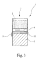
- the distance between the bottom edge of the shim 9 and the conveyor belt 6 is 2 millimeters across the entire width. Will the loosened two screws of the adjusting plate 9, so the gap height up to 1 millimeter reduced or increased to 5 mm.
- the bottom edge of the Adjustment plate 9, which is not shown in the drawing, is somewhat outward bent to smooth the emerging thin-bed mortar 9 and to compress something.
- the conveyor belt 6 always transports the mortar mass 2 into the rear area of the carriage 1 and presses the mortar 2 through the gap-shaped discharge opening 4, whereby a mortar strip 2 is produced which has the width B of the stones to be coated and due to the height D M of the discharge opening is 2 millimeters thick. So that the finished mortar strip 2 easily detaches from the conveyor belt 6 and slides evenly onto the stone surface, a wire 8 is tensioned under the discharge opening 4 in the region of the rear deflection roller, which presses against the conveyor belt 6 and thus detaches the mortar strip 2 from the conveyor belt 6.
- the emerging mortar strip 2 is shown transparently in the area of the discharge opening 4 in order to be able to better represent the wire 8.
- two guide rollers 11 are also shown, which guide the carriage 1 laterally on the stones 3.
- a roller 12 extending transversely to the direction of travel is attached under the carriage 1 in the rear area as a replacement for the runners.
- FIG. 1b describes a variant of the mortar application slide 1 described above.
- both drive wheels 7 are arranged under the front slide part.
- a feast Gear wheel d connected to the right drive wheel 7 engages with another gear wheel c a, which in turn is fixed to the front deflection roller of the conveyor belt 6 connected is.
- the front deflection roller lies below due to the arrangement of the drive wheels 7 the front part of the conveyor belt 6, at a greater height than the second at the Discharge opening 4 located pulley.
- the conveyor belt 6 falls with the Inclination angle ⁇ , defined as the angle between the conveyor belt 6 and the stone surface, towards the rear part of the slide.
- Figure 3 shows schematically a vertical section through the filled with mortar 2 Job sled 1.
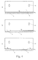
- FIG. 4 shows possible variants of the adjusting plate 9, by means of which not only the thickness D M of the mortar layer, but also the width B M of the emerging mortar strip 2 can be adjusted.
- FIG. 4a shows the simplest variant, which only allows the mortar strip thickness D M to be adjusted by adjusting the height.
- the mortar strip width B M can also be adjusted with the aid of the adjusting plate 9 shown in FIG. 4b.
- the lowermost edge of the sheet 9 touches the conveyor belt 6 over a certain width, so that no mortar 2 can escape at this point.
- a mortar strip 2 of width B M and thickness D M is formed through the remaining area.
- FIG. 4c shows a variant of an adjusting plate 9 with which two mortar strips 2 of width B M and thickness D M can be produced, which are applied, for example, only on the outer edge of the stones 3 to be coated.
Landscapes
- Engineering & Computer Science (AREA)
- Architecture (AREA)
- Mechanical Engineering (AREA)
- Civil Engineering (AREA)
- Structural Engineering (AREA)
- Devices For Post-Treatments, Processing, Supply, Discharge, And Other Processes (AREA)
- On-Site Construction Work That Accompanies The Preparation And Application Of Concrete (AREA)
- Finishing Walls (AREA)
- Curing Cements, Concrete, And Artificial Stone (AREA)
Abstract
Description
- Figur 1a
- zeigt in perspektivischer Ansicht eine Variante des erfindungsgemäßen Mörtelauftragschlitten mit vor dem Schlitten angeordneten Antriebsrädern
- Figur 1b
- zeigt einen Ausschnitt einer weiteren Variante des erfindungsgemäßen Mörtelauftragschlitten mit unter dem vorderen Schlittenteil angeordneten Antriebsrädern
- Figur 2
- zeigt schematisch eine seitliche Durchsicht durch den Schlitten und insbesondere die Anordnung der Mörtelfördervorrichtung
- Figur 3
- zeigt schematisch einen Schnitt durch einen befüllten Schlitten im Bereich der Austragsöffnung
- Figur 4
- zeigt verschiedene Varianten von Blechen zur Einstellung der Mörtelstreifenbreite und -dicke
- 1
- Mörtelauftragschlitten
- 2
- Dünnbettmörtel bzw. -mörtelstreifen
- 3
- Stein
- 4
- Austragsöffnung für Mörtel
- 5
- Einfüllöffnung für Mörtel
- 6
- Förderband
- 7
- Antriebsrad
- 8
- Draht
- 9
- Einstellblech
- 10
- Öffnung für Schraube
- 11
- senkrechte Führungsrolle
- 12
- Rolle
- 13
- Handgriff
- 14
- Kette zur Verbindung der Zahnräder a und d
- α
- Neigungswinkel zwischen Förderband und Steinoberfläche
- a
- Zahnrad
- b
- Zahnrad
- B
- Breite der Steine
- BM
- Breite des Mörtelstreifens bzw. Breite der Austragsöffnung
- c
- Zahnrad, mit Umlenkrolle des Förderbands verbunden
- d
- Zahnrad, mit Antriebsrad verbunden
- DM
- Dicke des Mörtelstreifens bzw. Höhe der Austragsöffnung
- L
- Länge des Schlittens
- s
- Verfahrrichtung
Claims (19)
- Verfahren zum Aufbringen von Dünnbettmörtel (2) in gleichmäßiger Dicke auf eine Seite von mehreren, nebeneinander angeordneten Steinen (3), insbesondere Hochlochsteinen, dadurch gekennzeichnet, daß zunächst ein Mörtelstreifen (2) vorgegebener Dicke (DM) und Breite (BM) ohne verstärkende Einlage geformt und dieser dann auf die Steinoberfläche aufgelegt wird.
- Verfahren nach Anspruch 1, dadurch gekennzeichnet, daß der Mörtelstreifen (2) vorgegebener Dicke (DM) und Breite (BM) auf einem Förderband (6) geformt wird.
- Verfahren nach Anspruch 1 oder 2, dadurch gekennzeichnet, daß die Dicke (DM) des Mörtelstreifens (2) durch eine Einstellvorrichtung, insbesondere eine Schablone oder ein Einstellblech (9), eingestellt wird.
- Verfahren nach einem der Ansprüche 1 bis 3, dadurch gekennzeichnet, daß die Breite (BM) des Mörtelstreifens (2) durch eine Einstellvorrichtung, insbesondere eine Schablone oder ein Einstellblech (9), eingestellt wird.
- Mörtelauftragschlitten zum Aufbringen von Dünnbettmörtel (2), auf eine Seite von mehreren, nebeneinander angeordneten Steinen (3), insbesondere Hochlochsteinen, der zwecks Aufbringung des Mörtels (2) in einer Verfahrrichtung (s) über die Steine (3) bewegt wird, mit einer Einfüllöffnung (5), einem umlaufenden Förderband (6) und einer Austragsöffnung (4), dadurch gekennzeichnet, daß die Austragsöffnung (4) unten durch das Förderband (6) und oben durch eine Einstellvorrichtung für die Dicke (DM) der Mörtelschicht begrenzt ist.
- Mörtelauftragschlitten nach Anspruch 5, dadurch gekennzeichnet, daß in Verfahrrichtung (s) hinter der Austragsöffnung (4) eine Vorrichtung angeordnet ist, die die Mörtelschicht vom Förderband (6) löst.
- Mörtelauftragschlitten nach Anspruch 6, dadurch gekennzeichnet, daß die den Mörtel (2) lösende Vorrichtung ein gespannter Draht (8) ist.
- Mörtelauftragschlitten nach einem der Ansprüche 5 bis 7, dadurch gekennzeichnet, daß die Einstellvorrichtung ein Einstellblech (9) ist.
- Mörtelauftragschlitten nach Anspruch 8, dadurch gekennzeichnet, daß das Einstellblech (9) auswärts gebogen ist.
- Mörtelauftragschlitten nach einem der Ansprüche 5 bis 9, dadurch gekennzeichnet, daß ein Teil der unteren Kante der Einstellvorrichtung das Förderband (6) berührt.
- Mörtelauftragschlitten nach einem der Ansprüche 5 bis 10, dadurch gekennzeichnet, daß der Mörtelvorratsraum des Schlittens (1) durch das umlaufende Förderband (6) unten verschlossen ist.
- Mörtelauftragschlitten nach einem der Ansprüche 5 bis 11, dadurch gekennzeichnet, daß das Förderband (6) in Verfahrrichtung (s) geneigt ist.
- Mörtelauftragschlitten nach einem der Ansprüche 5 bis 12, dadurch gekennzeichnet, daß er eine Vorrichtung zum Nachspannen des Förderbandes (6) aufweist.
- Mörtelauftragschlitten nach einem der Ansprüche 5 bis 13, dadurch gekennzeichnet, daß das Förderband (6) durch mindestens ein die Steine (3) berührendes mit dem Gehäuse des Mörtelauftragschlittens (1) verbundenes Antriebsrad (7) angetrieben wird.
- Mörtelauftragschlitten nach einem der Ansprüche 5 bis 14, dadurch gekennzeichnet, daß das Förderband (6) über ein Getriebe angetrieben wird, das ganz oder teilweise von einer Verkleidung umgeben ist.
- Mörtelauftragschlitten nach einem der Ansprüche 5 bis 15, dadurch gekennzeichnet, daß das Antriebsrad (7) derart angeordnet ist, daß es einen Teil des Gewichts des Mörtelauftragschlittens (1) trägt.
- Mörtelauftragschlitten nach einem der Ansprüche 5 bis 16, dadurch gekennzeichnet, daß das Antriebsrad (7) unter dem in Verfahrrichtung (s) vorderen Teil des Mörtelauftragschlittens (1) angeordnet ist.
- Mörtelauftragschlitten nach einem der Ansprüche 5 bis 17, dadurch gekennzeichnet, daß mindestens ein senkrechtes Führungsrad oder eine senkrechte Führungsrolle (11) zur seitlichen Führung des Schlittens (1) an ihm angeordet ist.
- Verwendung eines Mörtelauftragschlittens (1) nach einem der Ansprüche 5 bis 18 zur Durchführung des Verfahrens nach einem der Ansprüche 1 bis 4.
Applications Claiming Priority (2)
| Application Number | Priority Date | Filing Date | Title |
|---|---|---|---|
| DE10054900 | 2000-11-06 | ||
| DE10054900A DE10054900B4 (de) | 2000-11-06 | 2000-11-06 | Verfahren und Vorrichtung zum Aufbringen von Dünnbettmörtel |
Publications (3)
| Publication Number | Publication Date |
|---|---|
| EP1221516A2 true EP1221516A2 (de) | 2002-07-10 |
| EP1221516A3 EP1221516A3 (de) | 2003-09-17 |
| EP1221516B1 EP1221516B1 (de) | 2006-04-12 |
Family
ID=7662267
Family Applications (1)
| Application Number | Title | Priority Date | Filing Date |
|---|---|---|---|
| EP01123713A Expired - Lifetime EP1221516B1 (de) | 2000-11-06 | 2001-10-04 | Verfahren und Vorrichtung zum Aufbringen von Dünnbettmörtel |
Country Status (3)
| Country | Link |
|---|---|
| EP (1) | EP1221516B1 (de) |
| AT (1) | ATE323203T1 (de) |
| DE (2) | DE10054900B4 (de) |
Cited By (15)
| Publication number | Priority date | Publication date | Assignee | Title |
|---|---|---|---|---|
| WO2014026256A1 (pt) * | 2012-08-13 | 2014-02-20 | Ecker Cesar Roque | Aplicador de argamassa |
| CN107401285A (zh) * | 2017-09-27 | 2017-11-28 | 安徽理工大学 | 半自动摊浆式砌墙机及施工方法 |
| CN108385992A (zh) * | 2018-01-30 | 2018-08-10 | 云南工程建设总承包股份有限公司 | 一种控制墙体砌筑灰缝厚度的铺浆工具 |
| CN108678350A (zh) * | 2018-08-13 | 2018-10-19 | 安阳市国龙机械有限公司 | 一种电动瓷砖砂浆涂抹机 |
| CN108798044A (zh) * | 2017-11-22 | 2018-11-13 | 鞠德华 | 筑墙用均匀涂浆桶 |
| CN110512884A (zh) * | 2019-07-09 | 2019-11-29 | 中航勘察设计研究院有限公司 | 用于地铁隔墙砌筑的抹灰工具 |
| CN111350360A (zh) * | 2020-03-06 | 2020-06-30 | 郑永铿 | 一种建筑工地用推拉式抹水泥装置 |
| CN113638578A (zh) * | 2021-08-13 | 2021-11-12 | 青岛一建集团有限公司 | 一种墙面装饰施工专用智能瓷砖铺贴装置 |
| CN114263333A (zh) * | 2020-09-16 | 2022-04-01 | 广东博智林机器人有限公司 | 界面处理装置、铺砖机器人及其铺砖方法 |
| CN114855803A (zh) * | 2022-04-22 | 2022-08-05 | 北京路桥瑞通科技发展有限公司 | 一种边坡/护坡、挡墙砌缝快速抹平装置 |
| CN114905798A (zh) * | 2022-06-17 | 2022-08-16 | 江西省新华丽印务包装有限公司 | 一种防火防爆型纸质包装箱合制设备 |
| CN114961303A (zh) * | 2022-04-27 | 2022-08-30 | 中国建筑第七工程局有限公司 | 一种墙体砌筑砂浆摊平及灰缝收缝装置 |
| CN115749326A (zh) * | 2022-11-07 | 2023-03-07 | 中建八局第二建设有限公司 | 一种高效砖砌体砂浆摊铺车 |
| CN116122603A (zh) * | 2023-02-17 | 2023-05-16 | 中国十七冶集团有限公司 | 一种砌筑砂浆自动铺设装置 |
| CN117513779A (zh) * | 2023-11-07 | 2024-02-06 | 浙江信宇建设集团有限公司 | 一种砌体灰缝厚度控制装置及方法 |
Families Citing this family (5)
| Publication number | Priority date | Publication date | Assignee | Title |
|---|---|---|---|---|
| DE20311353U1 (de) * | 2003-07-23 | 2004-12-02 | Gustav Pfohl Gmbh | Auftragsgerät |
| FR2869929A1 (fr) * | 2004-05-04 | 2005-11-11 | Jean Pierre Valeux | Distributeur de mortier ou autre lien pour la construction en batiment |
| DE102004038334B3 (de) | 2004-07-07 | 2005-11-17 | Quick-Mix Gruppe Gmbh & Co. Kg | Mörtelauftragsvorrichtung für Dünnbettmörtel |
| CN110242059B (zh) * | 2019-06-28 | 2021-08-13 | 中国建筑第七工程局有限公司 | 一种砌筑砂浆快速铺设防落装置 |
| CN114991504B (zh) * | 2022-08-03 | 2022-11-11 | 无锡市锡山三建实业有限公司 | 一种用于建筑施工的砌砖装置 |
Family Cites Families (12)
| Publication number | Priority date | Publication date | Assignee | Title |
|---|---|---|---|---|
| DE894759C (de) * | 1938-07-10 | 1953-10-26 | Wilhelm Dr-Ing Ludowici | Vorrichtung zum Aufbringen von Moertel auf die Fugenflaeche von Mauerwerk od. dgl. |
| FR1096113A (fr) * | 1954-03-20 | 1955-06-09 | Appareil pour la maçonnerie | |
| GB753558A (en) * | 1954-04-23 | 1956-07-25 | Pierre Rossouw | Improved mortar spreader |
| US4043487A (en) * | 1975-07-29 | 1977-08-23 | Price Norris F | Mortar applying machine |
| DE7534981U (de) * | 1975-11-04 | 1976-03-11 | Bachmann, Johann, 8071 Hepberg | Moertelhobel |
| FR2392196A1 (fr) * | 1977-05-23 | 1978-12-22 | Secatol | Distributeur regleur de mortier pour la confection de murs en briques ou autres agglomeres |
| FR2638478A1 (fr) * | 1988-10-28 | 1990-05-04 | Trutin Bernard | Appareil de maconnerie |
| DE8903219U1 (de) * | 1989-03-15 | 1989-06-22 | Bäder, Wilfried, 7305 Altbach | Mörtelschlitten |
| DE4218143C1 (de) * | 1992-06-02 | 1993-07-15 | Deutsche Perlite Gmbh, 4600 Dortmund, De | |
| DE4334096C2 (de) * | 1993-10-06 | 1996-03-14 | Schlagmann Baustoffwerke Gmbh | Auftragvorrichtung für Dünnbettmörtel |
| DE29718544U1 (de) * | 1997-10-18 | 1998-01-02 | Tubag Trass-, Zement- und Steinwerke GmbH, 56642 Kruft | Vorrichtung zum Aufbringen von Mörtel auf eine Seite von Steinen |
| DE10033842A1 (de) * | 2000-07-12 | 2002-01-24 | Tubag Trass Zement Stein | Mörtelauftragschlitten mit Fördervorrichtung |
-
2000
- 2000-11-06 DE DE10054900A patent/DE10054900B4/de not_active Expired - Fee Related
-
2001
- 2001-10-04 EP EP01123713A patent/EP1221516B1/de not_active Expired - Lifetime
- 2001-10-04 AT AT01123713T patent/ATE323203T1/de active
- 2001-10-04 DE DE50109491T patent/DE50109491D1/de not_active Expired - Lifetime
Cited By (19)
| Publication number | Priority date | Publication date | Assignee | Title |
|---|---|---|---|---|
| WO2014026256A1 (pt) * | 2012-08-13 | 2014-02-20 | Ecker Cesar Roque | Aplicador de argamassa |
| CN107401285A (zh) * | 2017-09-27 | 2017-11-28 | 安徽理工大学 | 半自动摊浆式砌墙机及施工方法 |
| CN108798044A (zh) * | 2017-11-22 | 2018-11-13 | 鞠德华 | 筑墙用均匀涂浆桶 |
| CN108385992A (zh) * | 2018-01-30 | 2018-08-10 | 云南工程建设总承包股份有限公司 | 一种控制墙体砌筑灰缝厚度的铺浆工具 |
| CN108678350A (zh) * | 2018-08-13 | 2018-10-19 | 安阳市国龙机械有限公司 | 一种电动瓷砖砂浆涂抹机 |
| CN110512884A (zh) * | 2019-07-09 | 2019-11-29 | 中航勘察设计研究院有限公司 | 用于地铁隔墙砌筑的抹灰工具 |
| CN111350360A (zh) * | 2020-03-06 | 2020-06-30 | 郑永铿 | 一种建筑工地用推拉式抹水泥装置 |
| CN114263333A (zh) * | 2020-09-16 | 2022-04-01 | 广东博智林机器人有限公司 | 界面处理装置、铺砖机器人及其铺砖方法 |
| CN114263333B (zh) * | 2020-09-16 | 2023-09-15 | 广东博智林机器人有限公司 | 铺砖机器人及其铺砖方法 |
| CN113638578A (zh) * | 2021-08-13 | 2021-11-12 | 青岛一建集团有限公司 | 一种墙面装饰施工专用智能瓷砖铺贴装置 |
| CN114855803A (zh) * | 2022-04-22 | 2022-08-05 | 北京路桥瑞通科技发展有限公司 | 一种边坡/护坡、挡墙砌缝快速抹平装置 |
| CN114855803B (zh) * | 2022-04-22 | 2023-12-15 | 北京路桥瑞通科技发展有限公司 | 一种边坡/护坡、挡墙砌缝快速抹平装置 |
| CN114961303A (zh) * | 2022-04-27 | 2022-08-30 | 中国建筑第七工程局有限公司 | 一种墙体砌筑砂浆摊平及灰缝收缝装置 |
| CN114905798A (zh) * | 2022-06-17 | 2022-08-16 | 江西省新华丽印务包装有限公司 | 一种防火防爆型纸质包装箱合制设备 |
| CN114905798B (zh) * | 2022-06-17 | 2023-08-04 | 江西省新华丽印务包装有限公司 | 一种防火防爆型纸质包装箱合制设备 |
| CN115749326A (zh) * | 2022-11-07 | 2023-03-07 | 中建八局第二建设有限公司 | 一种高效砖砌体砂浆摊铺车 |
| CN115749326B (zh) * | 2022-11-07 | 2024-05-24 | 中建八局第二建设有限公司 | 一种高效砖砌体砂浆摊铺车 |
| CN116122603A (zh) * | 2023-02-17 | 2023-05-16 | 中国十七冶集团有限公司 | 一种砌筑砂浆自动铺设装置 |
| CN117513779A (zh) * | 2023-11-07 | 2024-02-06 | 浙江信宇建设集团有限公司 | 一种砌体灰缝厚度控制装置及方法 |
Also Published As
| Publication number | Publication date |
|---|---|
| DE10054900A1 (de) | 2002-05-08 |
| DE50109491D1 (de) | 2006-05-24 |
| ATE323203T1 (de) | 2006-04-15 |
| EP1221516B1 (de) | 2006-04-12 |
| DE10054900B4 (de) | 2004-02-05 |
| EP1221516A3 (de) | 2003-09-17 |
Similar Documents
| Publication | Publication Date | Title |
|---|---|---|
| DE10054900B4 (de) | Verfahren und Vorrichtung zum Aufbringen von Dünnbettmörtel | |
| EP1189716B1 (de) | Einrichtung zum zuführen von pulver für eine vorrichtung zum schichtweisen herstellen eines dreidimensionalen objektes | |
| DE2947755A1 (de) | Spritzkabine | |
| DE202008017871U1 (de) | Vorrichtung zum Herstellen von Betonsteinen | |
| DE4329321A1 (de) | Vorrichtung zum Auftragen eines Klebstoffs oder Dünnbettmörtels | |
| EP1203858B1 (de) | Vorrichtung und Verfahren zum Aufbringen von Dünnbettmörtel | |
| DE102004038334B3 (de) | Mörtelauftragsvorrichtung für Dünnbettmörtel | |
| DE10054899C2 (de) | Vorrichtung und Verfahren zum Aufbringen von Dünnbettmörtel | |
| EP0909860B1 (de) | Vorrichtung zum Aufbringen von Mörtel auf eine Seite von Steinen | |
| DE3732390A1 (de) | Faserballenpresse | |
| DE4408845C2 (de) | Fertigungsanlage für Mauerelemente | |
| DE10011293A1 (de) | Vorrichtung zum Auftragen von Mörtelmasse | |
| DE10033842A1 (de) | Mörtelauftragschlitten mit Fördervorrichtung | |
| DE3323918A1 (de) | Vorrichtung zur herstellung lose gerollter backwaren, wie croissants, butterhoernchen oder dergleichen | |
| EP2740546A2 (de) | Auftragsmittel, umfassend eine Walze, zum Auftragen eines Materials auf einen Untergrund | |
| DE20021502U1 (de) | Vorrichtung zum Aufbringen von Dünnbettmörtel | |
| DE8903219U1 (de) | Mörtelschlitten | |
| DE20021501U1 (de) | Vorrichtung zum Aufbringen von Dünnbettmörtel | |
| DE441515C (de) | Vorrichtung zum Fuellen von Pressformen mit wenig plastischen Massen | |
| DE102010045992A1 (de) | Verfugungswerkzeug | |
| EP3434844A1 (de) | Mörtelschlitten | |
| DE19811636C2 (de) | Verfahren und Vorrichtung zum Auftrag von Mörtel | |
| DE4243269A1 (de) | Einbauvorrichtung für Estrich o. dgl. | |
| DE10039615C1 (de) | Vorrichtung zum Aufbringen von Dünnbettmörtel | |
| DE10061467A1 (de) | Vorrichtung und Verfahren zum Aufbringen von Dünnbettmörtel |
Legal Events
| Date | Code | Title | Description |
|---|---|---|---|
| PUAI | Public reference made under article 153(3) epc to a published international application that has entered the european phase |
Free format text: ORIGINAL CODE: 0009012 |
|
| AK | Designated contracting states |
Kind code of ref document: A2 Designated state(s): AT BE CH CY DE DK ES FI FR GB GR IE IT LI LU MC NL PT SE TR |
|
| AX | Request for extension of the european patent |
Free format text: AL;LT;LV;MK;RO;SI |
|
| PUAL | Search report despatched |
Free format text: ORIGINAL CODE: 0009013 |
|
| AK | Designated contracting states |
Kind code of ref document: A3 Designated state(s): AT BE CH CY DE DK ES FI FR GB GR IE IT LI LU MC NL PT SE TR |
|
| AX | Request for extension of the european patent |
Extension state: AL LT LV MK RO SI |
|
| 17P | Request for examination filed |
Effective date: 20040302 |
|
| AKX | Designation fees paid |
Designated state(s): AT BE CH CY DE DK ES FI FR GB GR IE IT LI LU MC NL PT SE TR |
|
| 17Q | First examination report despatched |
Effective date: 20050207 |
|
| RAP1 | Party data changed (applicant data changed or rights of an application transferred) |
Owner name: QUICK-MIX GRUPPE GMBH & CO. KG |
|
| GRAP | Despatch of communication of intention to grant a patent |
Free format text: ORIGINAL CODE: EPIDOSNIGR1 |
|
| GRAS | Grant fee paid |
Free format text: ORIGINAL CODE: EPIDOSNIGR3 |
|
| GRAA | (expected) grant |
Free format text: ORIGINAL CODE: 0009210 |
|
| AK | Designated contracting states |
Kind code of ref document: B1 Designated state(s): AT BE CH CY DE DK ES FI FR GB GR IE IT LI LU MC NL PT SE TR |
|
| PG25 | Lapsed in a contracting state [announced via postgrant information from national office to epo] |
Ref country code: IT Free format text: LAPSE BECAUSE OF FAILURE TO SUBMIT A TRANSLATION OF THE DESCRIPTION OR TO PAY THE FEE WITHIN THE PRESCRIBED TIME-LIMIT;WARNING: LAPSES OF ITALIAN PATENTS WITH EFFECTIVE DATE BEFORE 2007 MAY HAVE OCCURRED AT ANY TIME BEFORE 2007. THE CORRECT EFFECTIVE DATE MAY BE DIFFERENT FROM THE ONE RECORDED. Effective date: 20060412 Ref country code: IE Free format text: LAPSE BECAUSE OF FAILURE TO SUBMIT A TRANSLATION OF THE DESCRIPTION OR TO PAY THE FEE WITHIN THE PRESCRIBED TIME-LIMIT Effective date: 20060412 Ref country code: GB Free format text: LAPSE BECAUSE OF FAILURE TO SUBMIT A TRANSLATION OF THE DESCRIPTION OR TO PAY THE FEE WITHIN THE PRESCRIBED TIME-LIMIT Effective date: 20060412 Ref country code: NL Free format text: LAPSE BECAUSE OF FAILURE TO SUBMIT A TRANSLATION OF THE DESCRIPTION OR TO PAY THE FEE WITHIN THE PRESCRIBED TIME-LIMIT Effective date: 20060412 Ref country code: FI Free format text: LAPSE BECAUSE OF FAILURE TO SUBMIT A TRANSLATION OF THE DESCRIPTION OR TO PAY THE FEE WITHIN THE PRESCRIBED TIME-LIMIT Effective date: 20060412 |
|
| REG | Reference to a national code |
Ref country code: GB Ref legal event code: FG4D Free format text: NOT ENGLISH |
|
| REG | Reference to a national code |
Ref country code: CH Ref legal event code: EP |
|
| REF | Corresponds to: |
Ref document number: 50109491 Country of ref document: DE Date of ref document: 20060524 Kind code of ref document: P |
|
| REG | Reference to a national code |
Ref country code: IE Ref legal event code: FG4D Free format text: LANGUAGE OF EP DOCUMENT: GERMAN |
|
| PG25 | Lapsed in a contracting state [announced via postgrant information from national office to epo] |
Ref country code: SE Free format text: LAPSE BECAUSE OF FAILURE TO SUBMIT A TRANSLATION OF THE DESCRIPTION OR TO PAY THE FEE WITHIN THE PRESCRIBED TIME-LIMIT Effective date: 20060712 Ref country code: DK Free format text: LAPSE BECAUSE OF FAILURE TO SUBMIT A TRANSLATION OF THE DESCRIPTION OR TO PAY THE FEE WITHIN THE PRESCRIBED TIME-LIMIT Effective date: 20060712 |
|
| PG25 | Lapsed in a contracting state [announced via postgrant information from national office to epo] |
Ref country code: ES Free format text: LAPSE BECAUSE OF FAILURE TO SUBMIT A TRANSLATION OF THE DESCRIPTION OR TO PAY THE FEE WITHIN THE PRESCRIBED TIME-LIMIT Effective date: 20060723 |
|
| PG25 | Lapsed in a contracting state [announced via postgrant information from national office to epo] |
Ref country code: PT Free format text: LAPSE BECAUSE OF FAILURE TO SUBMIT A TRANSLATION OF THE DESCRIPTION OR TO PAY THE FEE WITHIN THE PRESCRIBED TIME-LIMIT Effective date: 20060912 |
|
| NLV1 | Nl: lapsed or annulled due to failure to fulfill the requirements of art. 29p and 29m of the patents act | ||
| PG25 | Lapsed in a contracting state [announced via postgrant information from national office to epo] |
Ref country code: MC Free format text: LAPSE BECAUSE OF NON-PAYMENT OF DUE FEES Effective date: 20061031 Ref country code: LI Free format text: LAPSE BECAUSE OF NON-PAYMENT OF DUE FEES Effective date: 20061031 Ref country code: CH Free format text: LAPSE BECAUSE OF NON-PAYMENT OF DUE FEES Effective date: 20061031 |
|
| GBV | Gb: ep patent (uk) treated as always having been void in accordance with gb section 77(7)/1977 [no translation filed] |
Effective date: 20060412 |
|
| REG | Reference to a national code |
Ref country code: IE Ref legal event code: FD4D |
|
| PLBE | No opposition filed within time limit |
Free format text: ORIGINAL CODE: 0009261 |
|
| STAA | Information on the status of an ep patent application or granted ep patent |
Free format text: STATUS: NO OPPOSITION FILED WITHIN TIME LIMIT |
|
| 26N | No opposition filed |
Effective date: 20070115 |
|
| EN | Fr: translation not filed | ||
| REG | Reference to a national code |
Ref country code: CH Ref legal event code: PL |
|
| BERE | Be: lapsed |
Owner name: QUICK-MIX GRUPPE G.M.B.H. & CO. KG Effective date: 20061031 |
|
| PG25 | Lapsed in a contracting state [announced via postgrant information from national office to epo] |
Ref country code: GR Free format text: LAPSE BECAUSE OF FAILURE TO SUBMIT A TRANSLATION OF THE DESCRIPTION OR TO PAY THE FEE WITHIN THE PRESCRIBED TIME-LIMIT Effective date: 20060713 Ref country code: FR Free format text: LAPSE BECAUSE OF FAILURE TO SUBMIT A TRANSLATION OF THE DESCRIPTION OR TO PAY THE FEE WITHIN THE PRESCRIBED TIME-LIMIT Effective date: 20070309 |
|
| PG25 | Lapsed in a contracting state [announced via postgrant information from national office to epo] |
Ref country code: LU Free format text: LAPSE BECAUSE OF NON-PAYMENT OF DUE FEES Effective date: 20061004 Ref country code: TR Free format text: LAPSE BECAUSE OF FAILURE TO SUBMIT A TRANSLATION OF THE DESCRIPTION OR TO PAY THE FEE WITHIN THE PRESCRIBED TIME-LIMIT Effective date: 20060412 |
|
| PG25 | Lapsed in a contracting state [announced via postgrant information from national office to epo] |
Ref country code: FR Free format text: LAPSE BECAUSE OF FAILURE TO SUBMIT A TRANSLATION OF THE DESCRIPTION OR TO PAY THE FEE WITHIN THE PRESCRIBED TIME-LIMIT Effective date: 20060412 Ref country code: CY Free format text: LAPSE BECAUSE OF FAILURE TO SUBMIT A TRANSLATION OF THE DESCRIPTION OR TO PAY THE FEE WITHIN THE PRESCRIBED TIME-LIMIT Effective date: 20060412 |
|
| PG25 | Lapsed in a contracting state [announced via postgrant information from national office to epo] |
Ref country code: BE Free format text: LAPSE BECAUSE OF FAILURE TO SUBMIT A TRANSLATION OF THE DESCRIPTION OR TO PAY THE FEE WITHIN THE PRESCRIBED TIME-LIMIT Effective date: 20061031 |
|
| REG | Reference to a national code |
Ref country code: DE Ref legal event code: R082 Ref document number: 50109491 Country of ref document: DE Representative=s name: VON ROHR PATENTANWAELTE PARTNERSCHAFT MBB, DE |
|
| PGFP | Annual fee paid to national office [announced via postgrant information from national office to epo] |
Ref country code: DE Payment date: 20171019 Year of fee payment: 17 |
|
| PGFP | Annual fee paid to national office [announced via postgrant information from national office to epo] |
Ref country code: AT Payment date: 20171020 Year of fee payment: 17 |
|
| REG | Reference to a national code |
Ref country code: DE Ref legal event code: R119 Ref document number: 50109491 Country of ref document: DE |
|
| REG | Reference to a national code |
Ref country code: AT Ref legal event code: MM01 Ref document number: 323203 Country of ref document: AT Kind code of ref document: T Effective date: 20181004 |
|
| PG25 | Lapsed in a contracting state [announced via postgrant information from national office to epo] |
Ref country code: DE Free format text: LAPSE BECAUSE OF NON-PAYMENT OF DUE FEES Effective date: 20190501 |
|
| PG25 | Lapsed in a contracting state [announced via postgrant information from national office to epo] |
Ref country code: AT Free format text: LAPSE BECAUSE OF NON-PAYMENT OF DUE FEES Effective date: 20181004 |