EP1220253A2 - Mechanischer Beschleunigungssensor - Google Patents
Mechanischer Beschleunigungssensor Download PDFInfo
- Publication number
- EP1220253A2 EP1220253A2 EP01129368A EP01129368A EP1220253A2 EP 1220253 A2 EP1220253 A2 EP 1220253A2 EP 01129368 A EP01129368 A EP 01129368A EP 01129368 A EP01129368 A EP 01129368A EP 1220253 A2 EP1220253 A2 EP 1220253A2
- Authority
- EP
- European Patent Office
- Prior art keywords
- mass body
- switch according
- contact
- bearing arms
- switch
- Prior art date
- Legal status (The legal status is an assumption and is not a legal conclusion. Google has not performed a legal analysis and makes no representation as to the accuracy of the status listed.)
- Granted
Links
Images


Classifications
-
- G—PHYSICS
- G01—MEASURING; TESTING
- G01P—MEASURING LINEAR OR ANGULAR SPEED, ACCELERATION, DECELERATION, OR SHOCK; INDICATING PRESENCE, ABSENCE, OR DIRECTION, OF MOVEMENT
- G01P15/00—Measuring acceleration; Measuring deceleration; Measuring shock, i.e. sudden change of acceleration
- G01P15/02—Measuring acceleration; Measuring deceleration; Measuring shock, i.e. sudden change of acceleration by making use of inertia forces using solid seismic masses
- G01P15/08—Measuring acceleration; Measuring deceleration; Measuring shock, i.e. sudden change of acceleration by making use of inertia forces using solid seismic masses with conversion into electric or magnetic values
- G01P15/135—Measuring acceleration; Measuring deceleration; Measuring shock, i.e. sudden change of acceleration by making use of inertia forces using solid seismic masses with conversion into electric or magnetic values by making use of contacts which are actuated by a movable inertial mass
-
- H—ELECTRICITY
- H01—ELECTRIC ELEMENTS
- H01H—ELECTRIC SWITCHES; RELAYS; SELECTORS; EMERGENCY PROTECTIVE DEVICES
- H01H35/00—Switches operated by change of a physical condition
- H01H35/14—Switches operated by change of acceleration, e.g. by shock or vibration, inertia switch
-
- H—ELECTRICITY
- H01—ELECTRIC ELEMENTS
- H01H—ELECTRIC SWITCHES; RELAYS; SELECTORS; EMERGENCY PROTECTIVE DEVICES
- H01H11/00—Apparatus or processes specially adapted for the manufacture of electric switches
- H01H2011/0081—Apparatus or processes specially adapted for the manufacture of electric switches using double shot moulding, e.g. for forming elastomeric sealing elements on form stable casing
-
- H—ELECTRICITY
- H01—ELECTRIC ELEMENTS
- H01H—ELECTRIC SWITCHES; RELAYS; SELECTORS; EMERGENCY PROTECTIVE DEVICES
- H01H35/00—Switches operated by change of a physical condition
- H01H35/14—Switches operated by change of acceleration, e.g. by shock or vibration, inertia switch
- H01H35/147—Switches operated by change of acceleration, e.g. by shock or vibration, inertia switch the switch being of the reed switch type
Definitions
- the invention relates to a switch with an acceleration attractively deflectable mass body through which a switching system can be actuated is.
- Such switches are required in vehicles to activate Only release restraint systems when one crashes into a vehicle indicative (negative) acceleration is determined. Functional safety Such a switch has to meet the highest requirements.
- a switch of this type is already known from DE 195 18 824 C1, in which the mass body slidably guided in a guide housing and by a Spring is loaded into a rest position.
- the mass body is rotationally symmetrical or formed as a ball.
- the mass body actuates an electrical contact, which in turn is preloaded into a rest position.
- the mass body In a first movement phase the mass body only moves up to the electrical contact. Only when its higher restoring force in addition to that of the mass body is overcome, the contact is made. This is supposed to a safe and lasting contact over a predetermined period of time without Contact bounces can be reached.
- the invention creates a switch with only a few simple components have a reliable and reproducible switching function guaranteed without any adjustment.
- the switch according to the invention with a response to acceleration deflectable mass body, by means of which a switching system can be actuated is characterized in that the mass body on two parallel, elastically deflectable Bearing arms is suspended, which has a first, firmly anchored end and a second, have a movable end to which the mass body is attached.
- the two elastic deflectable bearing arms form a parallelogram that guides the mass body essentially a parallel displacement when it is deflected imposes and at the same time exerts a restoring force. Because the mass body is preferred is held with a distance between the bearing arms on both sides, it remains when deflected without any contact with other components, so that its Movement is not hindered by any friction.
- Switch Conventional switches to enable the activation of restraint systems in vehicles can only respond to one direction of acceleration. They are usually designed for front impact.
- the invention Switch enables the control of two in the simplest way Switching systems, one for the front impact and one for the rear impact, since the Mass body can be deflected in two opposite directions.
- the switch is built on a base plate in which the fixed ends of the bearing arms are anchored. Mass body with storage and switching system are enclosed by a hood-like housing, which with the peripheral edge of the base plate is connected. In the base plate are also Anchored contact pins that directly attach the switch to a Allow circuit board.
- the switch can be made extremely compact. In the case of a cuboid housing, the edge length can be less than 20 mm be.
- the mass body has an actuating arm, which is connected to a spring contact element attacks.
- a normally closed contact is preferably used held in its open position by the actuating arm of the mass body as long as the mass body is in its undeflected rest state is located, and is released from the actuating arm when the mass body is deflected and automatically occupies the closed position. The movement of the mass body then has no further influence on the switching behavior of the switching system.
- Switching systems for example optical or magnetic Switching units.
- additional Switch signals are generated for different purposes, especially for Signals that can be used for diagnostic purposes.
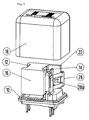
- the switch has a generally rectangular base plate 10 Plastic.
- the base plate 10 are two parallel, vertically towering Bearing arms 12, 14 anchored at their lower ends.
- the one shown in Figure 2 Embodiment are the ends anchored in the base plate 10 Bearing arms 12, 14 angled and completely in the material of the base plate embedded.
- the bearing arms 12, 14 can be deflected elastically and consist of Spring steel or a suitable plastic.
- a mass body 16 is attached at the top of the Bearing arms 12, 14, .
- the mass body 16 is in the shown embodiment generally cubic.
- the bearing arms 12, 14 form a guide parallelogram for the mass body 16, which at the upper ends the bearing arms 12, 14 are suspended.
- Figure 3 shows one in the area of the anchoring of the bearing arms 12, 14 in the Base plate 10 modified embodiment, in which the bearing arms moreover form an almost closed bracket that engages around the mass body 16.
- the Figure 3 shows the mass body 16 in the deflected state.
- a hood 18 is shown, which encloses the switch and at the peripheral edge of the Base plate 10 is attached.
- a leaf spring-like stop element 20 is provided to abut the mass body 16 on the To avoid the inside of the hood 18 .
- the mass body 16 has an integrally formed actuating arm 22 for one switching system generally designated 24.
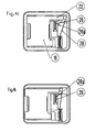
- the switching system 24 is in the Embodiment shown from an inside of the base plate 10 supported fixed contact 26, of which a contact pin through the Base plate 10 leads downward, and a movable contact 28, which as Spring bracket formed and also on the base plate 10th protruding contact pin 30 is attached.
- the movable contact 28 has one curved contact lug 28a, which with the fixed contact 26th interacts.
- the movable contact 28 is resilient against the fixed one Contact 26 is loaded and is actuated by the actuating arm 22 of the mass body 16 held in the open position as long as the mass body 16 is not in the is deflected hibernation. This state is shown in Figure 4a. If the Mass body 16 reaches the deflected position due to inertia (FIG 3), the operating arm 22 releases the movable contact 28 so that it Contact tab 28a comes into contact with the fixed contact 26, as in Figure 4b shown.
- the switching behavior of the switching system 24 is only by the properties of the movable Contact 28 determines because the mass body 16, the switching system with his Actuating arm 22 only opens and the contact is made solely by the Elasticity of the movable contact is determined. You can see that with simplest means and few components a safe, reproducible Switching function is achieved that requires no adjustment work.
- the permanent magnet 40 In the rest position of the mass body 16 the permanent magnet 40 is located vertically above the reed switch contact 44, which is then closed. Finally there is the permanent magnet 40 in the opposite deflection position, which is a rear impact of the Vehicle can correspond, vertically above the reed switch contact 46, which then closed is.
- optical solutions with a light barrier or reflector can be implemented like magnetic systems with Hall elements.
- all or almost all of them are Components of the switch are manufactured in a two-component injection molding technique.
- One of the two plastic components can be metallized and receives the necessary places a metal coating.
- the functional properties of the switch are determined, in particular the Mass of the mass body and the spring constant of the bearing arms, and consequently the Tripping threshold of the switch. Since the switch is a single molded part, all assembly steps can be omitted.
- the base plate has metallized contact surfaces, so that the switch as an SMD component directly on a circuit board can be put on and soldered.
Landscapes
- Physics & Mathematics (AREA)
- General Physics & Mathematics (AREA)
- Switches Operated By Changes In Physical Conditions (AREA)
- Push-Button Switches (AREA)
- Switches That Are Operated By Magnetic Or Electric Fields (AREA)
Abstract
Description
Claims (19)
- Schalter mit einem auf Beschleunigung ansprechend auslenkbaren Massekörper (16), durch den ein Schaltsystem (24) betätigbar ist, dadurch gekennzeichnet, dass der Massekörper (16) an zwei parallelen, elastisch auslenkbaren Lagerarmen (12, 14) aufgehängt ist, die ein erstes, fest verankertes Ende und ein zweites, bewegliches Ende haben, an dem der Massekörper (16) befestigt ist.
- Schalter nach Anspruch 1, dadurch gekennzeichnet, dass der Massekörper (16) mit beidseitigem Abstand zwischen den Lagerarmen (12, 14) gehalten ist.
- Schalter nach Anspruch 1 oder 2, dadurch gekennzeichnet, dass der Massekörper (16) ausgehend von einer Ruhestellung in zwei entgegengesetzte Richtungen auslenkbar ist.
- Schalter nach einem der vorstehenden Ansprüche, dadurch gekennzeichnet, dass die Lagerarme (12, 14) einen den Massekörper (16) umgreifenden durchgehenden Bügel bilden.
- Schalter nach Anspruch 4, dadurch gekennzeichnet, dass die Lagerarme (12, 14) an ihrem ersten Ende in einer Sockelplatte (10) verankert sind.
- Schalter nach einem der vorstehenden Ansprüche, dadurch gekennzeichnet, dass der Massekörper (16) einen Betätigungsarm (22) für das Schaltsystem (24) aufweist.
- Schalter nach Anspruch 6, dadurch gekennzeichnet, dass der Betätigungsarm (22) an einem elektromechanischen Kontaktelement (28) angreift
- Schalter nach Anspruch 7, dadurch gekennzeichnet, dass das Kontaktelement (28) ein Ruhekontaktelement ist, das durch Federkraft in eine Schließstellung belastet ist und durch den Betätigungsarm (22) des unausgelenkten Massekörpers (16) in einer Öffnungsstellung gehalten wird.
- Schalter nach Anspruch 7, dadurch gekennzeichnet, dass das Kontaktelement (28) ein Arbeitskontakt ist, der durch den Betätigungsarm (22) des ausgelenkten Massekörpers (16) geschlossen wird.
- Schalter nach Anspruch 8, dadurch gekennzeichnet, dass das Kontaktelement (28) ein an einem Kontaktstift (30) befestigtes Ende und ein bewegliches Kontaktfederelement aufweist.
- Schalter nach Anspruch 10, dadurch gekennzeichnet, dass der Kontaktstift (30) in einem Trägersockel verankert ist.
- Schalter nach einem der Ansprüche 5 bis 11, dadurch gekennzeichnet, dass der Massekörper (16) und das Schaltsystem (24) von einer Haube (18) umschlossen sind, die am Umfang der Sockelplatte (10) befestigt ist.
- Schalter nach Anspruch 12, dadurch gekennzeichnet, dass zwischen Massekörper (16) und Innenfläche der Haube (18) ein federndes Anschlagteil (20) angeordnet ist.
- Schalter nach einem der vorstehenden Ansprüche, dadurch gekennzeichnet, dass das Schaltsystem (24) Schalteinheiten (42, 44, 46) aufweist, die verschiedenen Stellungen des Massekörpers (16) zugeordnet sind.
- Schalter nach Anspruch 14, dadurch gekennzeichnet, dass eine (44) der Schalteinheiten der unausgelenkten Ruhestellung des Massekörpers (16) zugeordnet ist.
- Schalter nach Anspruch 14 oder 15, dadurch gekennzeichnet, dass jeder von zwei entgegengesetzten Auslenkstellungen des Massekörpers (16) eine Schalteinheit (42, 46) zugeordnet ist.
- Schalter nach einem der vorstehenden Ansprüche, dadurch gekennzeichnet, dass der Massekörper (16) ein magnetisches Betätigungselement aufweist.
- Schalter nach einem der vorstehenden Ansprüche, dadurch gekennzeichnet, dass der Massekörper (16) ein optisches Betätigungselement aufweist.
- Schalter nach einem der Ansprüche 5 bis 18, dadurch gekennzeichnet, dass die Sockelplatte (10), der Massekörper (16) und die Lagerarme (12, 14) in Zweikomponenten-Spritzgießtechnik hergestellt sind, wobei eine der Komponenten aus einem metallisierbaren Kunststoff besteht, und dass auf dem metallisierbaren Kunststoff wenigstens bereichsweise eine Metallschicht aufgebracht ist.
Applications Claiming Priority (2)
| Application Number | Priority Date | Filing Date | Title |
|---|---|---|---|
| DE20021531U DE20021531U1 (de) | 2000-12-20 | 2000-12-20 | Mechanischer Beschleunigungssensor |
| DE20021531U | 2000-12-20 |
Publications (3)
| Publication Number | Publication Date |
|---|---|
| EP1220253A2 true EP1220253A2 (de) | 2002-07-03 |
| EP1220253A3 EP1220253A3 (de) | 2002-07-10 |
| EP1220253B1 EP1220253B1 (de) | 2004-03-24 |
Family
ID=7950311
Family Applications (1)
| Application Number | Title | Priority Date | Filing Date |
|---|---|---|---|
| EP01129368A Expired - Lifetime EP1220253B1 (de) | 2000-12-20 | 2001-12-17 | Mechanischer Beschleunigungssensor |
Country Status (4)
| Country | Link |
|---|---|
| US (1) | US6610940B2 (de) |
| EP (1) | EP1220253B1 (de) |
| JP (1) | JP3921084B2 (de) |
| DE (2) | DE20021531U1 (de) |
Families Citing this family (2)
| Publication number | Priority date | Publication date | Assignee | Title |
|---|---|---|---|---|
| JP2005116371A (ja) * | 2003-10-08 | 2005-04-28 | Mitsubishi Electric Corp | 加速度検知装置 |
| DE102018216166B3 (de) * | 2018-09-21 | 2019-10-24 | Siemens Aktiengesellschaft | Messaufnehmer |
Family Cites Families (8)
| Publication number | Priority date | Publication date | Assignee | Title |
|---|---|---|---|---|
| JPS5858607B2 (ja) | 1977-07-19 | 1983-12-26 | 三菱電機株式会社 | 振動検出装置 |
| DE3713698C1 (de) * | 1987-04-24 | 1988-07-14 | Hopt & Schuler Ddm | Beschleunigungsschalter |
| US5231253A (en) * | 1989-02-23 | 1993-07-27 | Automotive Technologies, International | Side impact sensors |
| DE4126107C2 (de) | 1991-08-07 | 1993-12-16 | Bosch Gmbh Robert | Beschleunigungssensor und Verfahren zur Herstellung |
| DE4229068C2 (de) | 1992-09-01 | 1994-06-16 | Bosch Gmbh Robert | Beschleunigungsschalter und Verfahren zur Herstellung |
| US5496979A (en) * | 1994-03-11 | 1996-03-05 | Automotive Systems Laboratory, Inc. | Accelerometer with optical switch |
| JPH0999806A (ja) * | 1995-10-04 | 1997-04-15 | Nippon Arefu:Kk | セーフィングスイッチ |
| GB2343952B (en) * | 1998-11-18 | 2000-11-08 | Breed Automotive Tech | Pendulum mass acceleration sensor |
-
2000
- 2000-12-20 DE DE20021531U patent/DE20021531U1/de not_active Expired - Lifetime
-
2001
- 2001-12-17 DE DE50101753T patent/DE50101753D1/de not_active Expired - Lifetime
- 2001-12-17 US US10/023,551 patent/US6610940B2/en not_active Expired - Lifetime
- 2001-12-17 EP EP01129368A patent/EP1220253B1/de not_active Expired - Lifetime
- 2001-12-20 JP JP2001387441A patent/JP3921084B2/ja not_active Expired - Fee Related
Also Published As
| Publication number | Publication date |
|---|---|
| EP1220253B1 (de) | 2004-03-24 |
| DE20021531U1 (de) | 2001-03-01 |
| JP2002304938A (ja) | 2002-10-18 |
| DE50101753D1 (de) | 2004-04-29 |
| EP1220253A3 (de) | 2002-07-10 |
| JP3921084B2 (ja) | 2007-05-30 |
| US20020084176A1 (en) | 2002-07-04 |
| US6610940B2 (en) | 2003-08-26 |
Similar Documents
| Publication | Publication Date | Title |
|---|---|---|
| DE3216321C1 (de) | Magnetisch betaetigter elektrischer Schalter | |
| DE102013006414A1 (de) | Vorrichtung zur Bedienung mehrerer Funktionen in einem Kraftfahrzeug | |
| DE2362839B2 (de) | Schaltvorrichtung | |
| DE4035257C2 (de) | Beschleunigungssensor | |
| DE102010061455A1 (de) | Gehäuse für einen Tastschalter | |
| DE4409010A1 (de) | Elektromagnetische Schaltvorrichtung | |
| DE102010002325B4 (de) | Elektrisches Schaltelement | |
| EP1220253B1 (de) | Mechanischer Beschleunigungssensor | |
| EP0519940B1 (de) | Beschleunigungsschalter | |
| DE3713698C1 (de) | Beschleunigungsschalter | |
| DE4022164A1 (de) | Schaltervorrichtung | |
| EP0466021A2 (de) | Beschleunigungsschalter mit Schnappfeder | |
| DE4142759A1 (de) | Beschleunigungssensor | |
| DE60220272T2 (de) | Reedschalter mit stosserfassungsmasse | |
| EP0567024B1 (de) | Tastatur, insbesondere für klavierartige Instrumente | |
| DE4102992C1 (en) | Snap-action switch - has contact carriers and coil springs located against projections in housing and displaced by contact frame | |
| EP0803129A1 (de) | Mechanischer beschleunigungsschalter | |
| DE2246714A1 (de) | Schalttaste mit einer schnappmechanik | |
| DE3638504A1 (de) | Elektrische kontaktvorrichtung | |
| DE19508014C1 (de) | Mechanischer Beschleunigungsschalter | |
| DE3915069C2 (de) | ||
| EP0626707B1 (de) | Schalterkappe für Drucktastenschalter | |
| EP1207541A1 (de) | Mikroschalter mit verstärkter Kontaktkraft | |
| DE4315842A1 (de) | Beschleunigungsaufnehmer | |
| DE202006008453U1 (de) | Kickdown-Element und Fahrpedalvorrichtung |
Legal Events
| Date | Code | Title | Description |
|---|---|---|---|
| PUAI | Public reference made under article 153(3) epc to a published international application that has entered the european phase |
Free format text: ORIGINAL CODE: 0009012 |
|
| PUAL | Search report despatched |
Free format text: ORIGINAL CODE: 0009013 |
|
| AK | Designated contracting states |
Kind code of ref document: A2 Designated state(s): AT BE CH CY DE DK ES FI FR GB GR IE IT LI LU MC NL PT SE TR |
|
| AX | Request for extension of the european patent |
Free format text: AL;LT;LV;MK;RO;SI |
|
| AK | Designated contracting states |
Kind code of ref document: A3 Designated state(s): AT BE CH CY DE DK ES FI FR GB GR IE IT LI LU MC NL PT SE TR |
|
| AX | Request for extension of the european patent |
Free format text: AL;LT;LV;MK;RO;SI |
|
| GBC | Gb: translation of claims filed (gb section 78(7)/1977) | ||
| EL | Fr: translation of claims filed | ||
| 17P | Request for examination filed |
Effective date: 20021021 |
|
| AKX | Designation fees paid |
Designated state(s): DE FR GB |
|
| 17Q | First examination report despatched |
Effective date: 20030306 |
|
| GRAP | Despatch of communication of intention to grant a patent |
Free format text: ORIGINAL CODE: EPIDOSNIGR1 |
|
| GRAS | Grant fee paid |
Free format text: ORIGINAL CODE: EPIDOSNIGR3 |
|
| GRAA | (expected) grant |
Free format text: ORIGINAL CODE: 0009210 |
|
| AK | Designated contracting states |
Kind code of ref document: B1 Designated state(s): DE FR GB |
|
| REG | Reference to a national code |
Ref country code: GB Ref legal event code: FG4D Free format text: NOT ENGLISH |
|
| REG | Reference to a national code |
Ref country code: IE Ref legal event code: FG4D Free format text: GERMAN |
|
| REF | Corresponds to: |
Ref document number: 50101753 Country of ref document: DE Date of ref document: 20040429 Kind code of ref document: P |
|
| GBT | Gb: translation of ep patent filed (gb section 77(6)(a)/1977) |
Effective date: 20040520 |
|
| REG | Reference to a national code |
Ref country code: IE Ref legal event code: FD4D |
|
| ET | Fr: translation filed | ||
| PLBE | No opposition filed within time limit |
Free format text: ORIGINAL CODE: 0009261 |
|
| STAA | Information on the status of an ep patent application or granted ep patent |
Free format text: STATUS: NO OPPOSITION FILED WITHIN TIME LIMIT |
|
| 26N | No opposition filed |
Effective date: 20041228 |
|
| PGFP | Annual fee paid to national office [announced via postgrant information from national office to epo] |
Ref country code: FR Payment date: 20091221 Year of fee payment: 9 Ref country code: GB Payment date: 20091216 Year of fee payment: 9 |
|
| GBPC | Gb: european patent ceased through non-payment of renewal fee |
Effective date: 20101217 |
|
| REG | Reference to a national code |
Ref country code: FR Ref legal event code: ST Effective date: 20110831 |
|
| PG25 | Lapsed in a contracting state [announced via postgrant information from national office to epo] |
Ref country code: FR Free format text: LAPSE BECAUSE OF NON-PAYMENT OF DUE FEES Effective date: 20110103 |
|
| PG25 | Lapsed in a contracting state [announced via postgrant information from national office to epo] |
Ref country code: GB Free format text: LAPSE BECAUSE OF NON-PAYMENT OF DUE FEES Effective date: 20101217 |
|
| PGFP | Annual fee paid to national office [announced via postgrant information from national office to epo] |
Ref country code: DE Payment date: 20151229 Year of fee payment: 15 |
|
| REG | Reference to a national code |
Ref country code: DE Ref legal event code: R119 Ref document number: 50101753 Country of ref document: DE |
|
| PG25 | Lapsed in a contracting state [announced via postgrant information from national office to epo] |
Ref country code: DE Free format text: LAPSE BECAUSE OF NON-PAYMENT OF DUE FEES Effective date: 20170701 |