EP1219417A2 - Maskenerstellung zur Herstellung einer Druckform - Google Patents
Maskenerstellung zur Herstellung einer Druckform Download PDFInfo
- Publication number
- EP1219417A2 EP1219417A2 EP01129903A EP01129903A EP1219417A2 EP 1219417 A2 EP1219417 A2 EP 1219417A2 EP 01129903 A EP01129903 A EP 01129903A EP 01129903 A EP01129903 A EP 01129903A EP 1219417 A2 EP1219417 A2 EP 1219417A2
- Authority
- EP
- European Patent Office
- Prior art keywords
- mask
- laser
- thermal transfer
- creation
- induced thermal
- Prior art date
- Legal status (The legal status is an assumption and is not a legal conclusion. Google has not performed a legal analysis and makes no representation as to the accuracy of the status listed.)
- Granted
Links
- 238000007639 printing Methods 0.000 title claims abstract description 65
- 238000004519 manufacturing process Methods 0.000 title claims description 36
- 230000004069 differentiation Effects 0.000 claims abstract description 8
- 238000000034 method Methods 0.000 claims description 45
- 238000007650 screen-printing Methods 0.000 claims description 39
- 230000008569 process Effects 0.000 claims description 28
- 238000003384 imaging method Methods 0.000 claims description 26
- 239000000463 material Substances 0.000 claims description 24
- 238000005530 etching Methods 0.000 claims description 20
- 238000000576 coating method Methods 0.000 claims description 10
- 239000011248 coating agent Substances 0.000 claims description 9
- 239000002253 acid Substances 0.000 claims description 7
- 239000003792 electrolyte Substances 0.000 claims description 7
- 238000002679 ablation Methods 0.000 claims description 4
- 239000012212 insulator Substances 0.000 claims 1
- 230000000873 masking effect Effects 0.000 abstract description 11
- 239000011888 foil Substances 0.000 abstract description 5
- 239000000758 substrate Substances 0.000 description 16
- 230000005855 radiation Effects 0.000 description 11
- 230000008901 benefit Effects 0.000 description 10
- 238000004140 cleaning Methods 0.000 description 8
- 230000005540 biological transmission Effects 0.000 description 7
- 239000004744 fabric Substances 0.000 description 6
- 238000007646 gravure printing Methods 0.000 description 6
- 239000007788 liquid Substances 0.000 description 5
- 238000005406 washing Methods 0.000 description 5
- RYGMFSIKBFXOCR-UHFFFAOYSA-N Copper Chemical compound [Cu] RYGMFSIKBFXOCR-UHFFFAOYSA-N 0.000 description 3
- 238000003491 array Methods 0.000 description 3
- 238000010276 construction Methods 0.000 description 3
- 229910052802 copper Inorganic materials 0.000 description 3
- 239000010949 copper Substances 0.000 description 3
- 239000002184 metal Substances 0.000 description 3
- 229910052751 metal Inorganic materials 0.000 description 3
- 230000007723 transport mechanism Effects 0.000 description 3
- 108010010803 Gelatin Proteins 0.000 description 2
- XEEYBQQBJWHFJM-UHFFFAOYSA-N Iron Chemical compound [Fe] XEEYBQQBJWHFJM-UHFFFAOYSA-N 0.000 description 2
- PXHVJJICTQNCMI-UHFFFAOYSA-N Nickel Chemical compound [Ni] PXHVJJICTQNCMI-UHFFFAOYSA-N 0.000 description 2
- 229920000159 gelatin Polymers 0.000 description 2
- 239000008273 gelatin Substances 0.000 description 2
- 235000019322 gelatine Nutrition 0.000 description 2
- 235000011852 gelatine desserts Nutrition 0.000 description 2
- 238000000926 separation method Methods 0.000 description 2
- 239000000126 substance Substances 0.000 description 2
- 241001136792 Alle Species 0.000 description 1
- 101100043261 Caenorhabditis elegans spop-1 gene Proteins 0.000 description 1
- VEXZGXHMUGYJMC-UHFFFAOYSA-M Chloride anion Chemical compound [Cl-] VEXZGXHMUGYJMC-UHFFFAOYSA-M 0.000 description 1
- 230000009471 action Effects 0.000 description 1
- 239000000853 adhesive Substances 0.000 description 1
- 230000001070 adhesive effect Effects 0.000 description 1
- 230000001680 brushing effect Effects 0.000 description 1
- 238000006243 chemical reaction Methods 0.000 description 1
- 239000004567 concrete Substances 0.000 description 1
- 230000007547 defect Effects 0.000 description 1
- 230000001419 dependent effect Effects 0.000 description 1
- 230000008021 deposition Effects 0.000 description 1
- 238000003618 dip coating Methods 0.000 description 1
- 238000001035 drying Methods 0.000 description 1
- 230000000694 effects Effects 0.000 description 1
- 238000010894 electron beam technology Methods 0.000 description 1
- 238000009713 electroplating Methods 0.000 description 1
- 239000012530 fluid Substances 0.000 description 1
- 150000002505 iron Chemical class 0.000 description 1
- 229910052742 iron Inorganic materials 0.000 description 1
- FBAFATDZDUQKNH-UHFFFAOYSA-M iron chloride Chemical compound [Cl-].[Fe] FBAFATDZDUQKNH-UHFFFAOYSA-M 0.000 description 1
- 239000011244 liquid electrolyte Substances 0.000 description 1
- 238000001459 lithography Methods 0.000 description 1
- 230000007246 mechanism Effects 0.000 description 1
- 229910052759 nickel Inorganic materials 0.000 description 1
- 238000007645 offset printing Methods 0.000 description 1
- 239000002245 particle Substances 0.000 description 1
- 230000002688 persistence Effects 0.000 description 1
- 239000002861 polymer material Substances 0.000 description 1
- 238000001556 precipitation Methods 0.000 description 1
- 239000002994 raw material Substances 0.000 description 1
- 238000005096 rolling process Methods 0.000 description 1
- 239000007787 solid Substances 0.000 description 1
- 238000005507 spraying Methods 0.000 description 1
- 238000004381 surface treatment Methods 0.000 description 1
- 238000010345 tape casting Methods 0.000 description 1
- 230000004304 visual acuity Effects 0.000 description 1
Images



Classifications
-
- G—PHYSICS
- G03—PHOTOGRAPHY; CINEMATOGRAPHY; ANALOGOUS TECHNIQUES USING WAVES OTHER THAN OPTICAL WAVES; ELECTROGRAPHY; HOLOGRAPHY
- G03F—PHOTOMECHANICAL PRODUCTION OF TEXTURED OR PATTERNED SURFACES, e.g. FOR PRINTING, FOR PROCESSING OF SEMICONDUCTOR DEVICES; MATERIALS THEREFOR; ORIGINALS THEREFOR; APPARATUS SPECIALLY ADAPTED THEREFOR
- G03F1/00—Originals for photomechanical production of textured or patterned surfaces, e.g., masks, photo-masks, reticles; Mask blanks or pellicles therefor; Containers specially adapted therefor; Preparation thereof
- G03F1/68—Preparation processes not covered by groups G03F1/20 - G03F1/50
-
- B—PERFORMING OPERATIONS; TRANSPORTING
- B41—PRINTING; LINING MACHINES; TYPEWRITERS; STAMPS
- B41C—PROCESSES FOR THE MANUFACTURE OR REPRODUCTION OF PRINTING SURFACES
- B41C1/00—Forme preparation
- B41C1/10—Forme preparation for lithographic printing; Master sheets for transferring a lithographic image to the forme
- B41C1/1091—Forme preparation for lithographic printing; Master sheets for transferring a lithographic image to the forme by physical transfer from a donor sheet having an uniform coating of lithographic material using thermal means as provided by a thermal head or a laser; by mechanical pressure, e.g. from a typewriter by electrical recording ribbon therefor
Definitions
- the invention relates to a mask creation for the production of a printing form.
- masks are used in many technical fields Surface treatment (circuit board production) or also for printing (gravure printing, which does not apply printing forms, but rather the forme cylinder surfaces are prepared as printing forms) or lithography processes become.
- the goal is always with one material, the other Properties as a substrate, that is a carrier one with regard to the Mask material of other material, a certain structure (mask) on the same To produce substrate.
- the mask created in this way then serves as a starting point for further processes. It should e.g. the substrate at certain points before Protect the action of other substances.
- A is used to create the structure information of a mask Thermal transfer film used by a suitable feed device in Contact with the substrate, i.e. brought to the surface of the printing form carrier becomes.
- An energy sensitive layer can also be coated directly on the Substrate (e.g. by dip coating, knife coating, spraying on, rolling on or Concretes with solid or liquid toner), possibly in combination with a Post-drying or curing step are applied to this Structure information of the mask is placed.
- the structure information is preferably generated by means of laser radiation, and a power density of more than 500 MW / m 2, possibly pulsed, is preferably provided for ablation.
- the laser radiation is modulated in a suitable manner in terms of image or non-image in order to produce the desired mask.
- DE 198 11 031 A1 describes a method and in particular one Device for producing a print using the laser-induced Thermal transfers using a ribbon-shaped transfer film and one Substrate cylinders become known.
- the known device comprises one Belt transport mechanism that with one with the one or more (Laser diode array) coupled imaging unit emitting laser beams Traversing unit interacts.
- the transfer film is thus uniform Movement movable across the substrate width of a printing form cylinder, the by means of a control unit in a known manner according to one transferring image driven laser based thermal printhead at each Pixel introduces heat to the transfer film and thus a selective Transfer of the coating (thermal material) of the transfer film and being about the rotation of the substrate cylinder and that to the substrate cylinder axially parallel traversing the entire substrate surface can be painted over.
- the Development / cleaning of the layer with a suitable cleaning device possibly with the help of cleaning fluids, i.e. cleaning by liquid or particle jet, combined if necessary, or cleaning by Brushing or cleaning with a washcloth.
- the layer after Forming the mask can still be thermally applied to its Chemical resistance or mechanical properties to improve.
- the method on which the proposal for the invention is based is laser-induced thermal transfer, such as that used to manufacture the erasable Offset printing forms, for example in the subject of DE 44 30 555 C1 is used.
- the system arrangement from the components laser and Belt station, as known from DE 44 30 555 C1 or DE 198 11 031 A1 (Thermal transfer offpress construction), is the model for a device for Mask making.
- Laser-induced thermal transfer offers compared to conventional processes
- the advantage of mask creation is that it is very fast and precise.
- By the Laser-induced thermal transfer are the process steps of coating and of the imaging combined into one process step. This can take time and costs can be saved.
- the imaging quality of the laser-induced thermal transfer is very high (Offset quality) so that the finest structures can be reproduced.
- Thermal transfer material which is applied to the printing form to be produced is suitable for mask creation by exposure, washing out or Etching to be used.
- the thermal transfer material is opaque (lightfast), waterproof and especially acid-resistant.
- the thermal transfer material does not have to be applied separately. On thin foil tapes applied, as is known, come pre-assembled Tape cassettes for use. In addition, both the creation of the mask and also the production of a printing form using this mask within the Printing machine can be made.
- Fig. 1 shows a printing form cylinder 1, on the surface of which Mask should be created.
- a tape transport mechanism 2 a supply 3 and comprising a take-up roll 4, guides a ribbon-shaped thermal transfer film 5 close to the surface of the printing form cylinder 1, or brings it into contact with the surface of the printing form cylinder 1.
- a laser imaging unit 6 focuses one or more laser beams 7 on the thermal transfer film 5. Die Laser imaging unit 6 and tape guide mechanism 2 are shown in FIG arranged in a known manner together on a traversing unit 8, by means of this in a machine frame 9 across the width of the printing form cylinder 1 can be moved.
- FIG. 2 shows again how the device according to FIG Rotogravure machine is used to an etching mask 10 (Fig. 3, or 4) by means of laser-induced thermal transfer on the surface 11 of a Gravure cylinder to be created by using thermal transfer material 5b Image information 5c, or structure information for the etching mask 10 is transmitted.
- a mask can be created by means of laser-induced Thermal transfer can be used to produce a gravure form 13.
- a gravure form 13 there is an etching process, in which in a conventional manner Iron III chloride (Fe3Cl) image information on a printing cylinder with a Copper top layer can be etched.
- Fe3Cl Iron III chloride
- Fig. 3 the process is the Mask creation for a gravure form indicated and they are the same Reference numerals for the same parts of FIGS. 1 and 2 are used.
- Fig. 4 shows the etching process in rotogravure using a Etching mask 10 produced according to the invention.
- a differentiation is made with regard to Image locations and non-image locations (image information 5c).
- the etching mask 10 is transferred from the transfer film 5 in the form of the thermal transfer material 5b Negative mask applied so that the intended image areas 14 as free and areas not covering are recognizable.
- the non-image areas 15 must be covered and protected.
- the gravure printing plate 13 can be etched, whereby by the application of acid 16 the cylinder surface 11 at the image points 14, i.e. the unprotected areas, attacked or deepened by the etching process, and so that intaglio cups 18 are formed.
- the acid 16 reaches through chemical reaction the surface material, generally in gravure forms the copper, and dissolves it.
- the material 5b that forms the image-differentiating mask 10 must Resistant to acid and must not be attacked by it. By this persistence becomes the image differentiation or the image generation on the Gravure plate 13 guaranteed.
- the mask material 5b is also called etch resistance or etching reserve.
- the liability of the mask material 5b on the Printing form surface 11 must be firm and even. It must be guaranteed be that the acid 16 cannot underflow or flood the mask 10. This adhesive strength guarantees sharp and exact edges at the same time Image generation, which is mainly for lines and fonts of the greatest Meaning and necessity.
- the ones necessary for gravure printing squeegee-bearing structures must have appropriate Image data generation during mask creation through laser imaging to be guaranteed.
- a polymer material used which is in thin layers a film carrier is applied.
- This coated thermal transfer film 5 is as described at the beginning on a supply roll 3 and is wound on a appropriate device in the process of mask creation.
- the leadership of the film strip 5 is aligned in such a way that the Mask material 5b coated side of the film 5 the surface of the Printing form cylinder 1 is assigned.
- a laser system 6 for image generation.
- This preferably diode-pumped YAG laser system 6 transmits the image signals from a digital database using high-energy laser pulses on the Back of the film 5 coated with the mask material 5b.
- the distance of the Foil 5 to the cylinder surface must be very small, so that the Mask material 5b as soon as the high-energy laser radiation 7 on the Back of the film meets, from the front of the film with sufficient accuracy and Completeness can be transported to the surface of the cylinder 1.
- the cylinder rotation speed and the speed of the Foil tape feeds are dependent on the performance of the laser system certainly.
- the lateral feed in the parallel direction of the cylinder axis is given by the number of laser diode arrays.
- the principle of the rotary Illustration with laterally traversing feed ensures the possibility a seamless mask creation on the rotogravure roller to be processed.
- Laser-induced mask creation is an autotypical one Image construction method, i.e. that the image information is variable in area with simultaneous Constant layer thickness is applied.
- the mask must be successful Processing in the etching process have been transferred in the negative process.
- the Image areas 14, that is, the intaglio printing cups 18, which are based on the intaglio printing plate Etching should be deepened, must be clearly exposed after masking, i.e. these areas must not be covered by the etching mask 10.
- the non-image passages 15 must be visibly covered by the negative mask.
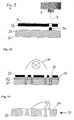
- the Fig. 5 shows such an etched intaglio printing form 13 with the etching mask 10 and 12 already removed with etched intaglio cups 18 and grid bars 17.
- FIG. 6 indicates another embodiment of the present invention a mask creation for producing a flexographic printing plate 20
- Fig. 7 outlines shows a copying process of a flexographic printing form 20 by means of mask 21
- FIG. 8 a developed flexographic printing form 20 with the mask already removed.
- the mask can be created by means of laser-induced Thermal transfer further used to produce a flexographic printing plate 20 become. It is a copying process in which the Image information using a copy mask 21 and high-energy radiation (e.g. UV light from a copying lamp 22, Fig. 7) on a light-sensitive Coating 23 of a flexographic printing form 20 are transferred. With the Copy mask 21 becomes a differentiation with regard to image areas 24 and non-image areas 25 (Figs. 6 and 7).
- high-energy radiation e.g. UV light from a copying lamp 22, Fig. 7
- Requirement for the Copying process for producing a flexographic printing form 20 is that of Flexographic cylinder or the sleeve, which are pushed onto this can, as well as the raw plate, which is clamped on a corresponding cylinder can be precoated with a light-sensitive material 23.
- This coating is not part of the production of flexographic printing plates, but rather is prefabricated as raw material by corresponding manufacturers or suppliers delivered. These pre-coatings have so-called negative or Positive materials, i.e. that the exposure of these copy materials on the one hand by means of a positive copy mask or to another by means of a Negative copy mask can be done.
- the image areas 24 thus result from the permeable regions of the Negative mask 21, the non-image areas 25 result from the covered Areas of the mask 21.
- the hardened picture elements 24 protrude Fig. 8
- Flexographic printing plate 20 can be used on a flexographic printing cylinder.
- the mask 21 transferred by means of laser-induced thermal transfer serves in the Production of flexographic printing plates exclusively for the transmission of image information 5c by copying or by irradiation with high-energy light (e.g. UV light).
- the task of the copy mask 21 is sufficient opacity in the To ensure radiation.
- the image information must be exact and can be shown with sharp edges. Shining through and missing parts in the Mask 21 lead to imperfections on the flexographic printing plate 20. For the process step the developing or washing out the copy mask 21 is no longer required.
- the execution of the mask creation by means of laser-induced thermal transfer is similar to the execution of gravure except for the fact that at Mask creation for the production of flexographic printing plates as well as negative copy masks as well as positive masks can be used.
- Flexographic printing plate production makes the mask for exposure to high energy Radiation (e.g. UV light) is used and comes from the transmission of Image information not in contact with liquid media.
- high energy Radiation e.g. UV light
- the device for Production of the copy mask 21 for flexographic printing plate production is with the Gravure mask creation identical.
- the advantage here is the simultaneous creation of an opaque copy mask and the transmission of the image information. Through this procedure the Separation of masking and ablative imaging removed. Consequently can have two process steps for masking a copy form onto one Process step can be shortened. Imaging using a laser diode array is permitted short imaging times due to lower energy requirements and higher feed speeds in the laterally parallel axis direction. On Another advantage lies in the quality of the imaging. The The resolution of laser-induced imaging is compared to that of only ablative laser imaging higher. Result from these advantages on the one hand time savings in the process flow and on the other hand Cost savings in the device construction by saved Components.
- the mask can be created by means of laser-induced Thermal transfer can also be used to produce a screen printing form. So it can either be a copying process (Fig. 9 to 11) or a Masking process for a galvanic manufacturing process (Fig. 12 to 14) act.
- Screen printing stencils 30 (screen printing form, Fig. 11) made, it is mostly a mesh-like fabric structure 31 (screen printing fabric) that is clamped in a frame or in a suitable frame.
- This net-like tissue is completed with a light-sensitive layer 32 coated and can with a suitable mask 33 for the transfer of Image information 5c with high-energy radiation (e.g. UV light from a Copy lamp 34) are irradiated.
- high-energy radiation e.g. UV light from a Copy lamp 34
- FIG. 10 shows the copying process for screen printing form production using a mask 33.
- a mask 33 For the copying process, depending on the one used Mask material positive or negative masks are used. at Negative masks turn the exposed areas of the mask into non-image areas on the screen printing form. The areas hit by the radiation photosensitive layer are hardened and remain during development or Get the printing plate washed out. Unhardened areas of the photosensitive layer on the printing plate are washed out and form thus the permeable image areas on the screen printing form. With positive masks 33 this principle of operation is reversed, i.e. those hit by the radiation Areas (image areas 36) are destroyed and washed out during development. Here, the exposed areas become image areas 36, or the covered areas Areas to non-image areas 37 on the screen printing form 30.
- the means Laser-induced thermal transfer mask 33 is used in the Screen printing form production on net-like fabrics 31 exclusively for Transmission of the image information by copying or by irradiation with high-energy light (e.g. UV light).
- the copying mask 33 must have sufficient opacity during the irradiation guarantee.
- the image information must be reproduced precisely and with sharp edges can be. Shining through and missing parts in the mask 33 lead to Defects on the screen printing form 30. For the process step of development or washing out, the copy mask 33 is no longer required.
- the thermal transfer material 5b, 5c of the mask 41 serves as Isolator, so that at the points or areas (image points 44) where the Mask 41 is located on the surface (separating layer 42) of the base cylinder 40, no electrical charge can flow (the metallic separating layer 42 is negative, the electrolyte 43 is positively charged (FIG. 13). Thus can be at this by the Mask 41 covered areas 44 no metal precipitation take place, i.e. the Effect of the deposition of metal (e.g. copper, nickel) by the electrolyte bath can be controlled by this masking.
- metal e.g. copper, nickel
- a sleeve from the metallic cylinder (base cylinder 40) are subtracted, which can then be used as a screen printing form 45.
- a screen printing form 45 To the Places 44 where the positive mask 41 on the base cylinder 40, 42 die Covered surface are on the screen printing form 45 (sleeve) corresponding Holes or image points 41 are present (FIG. 11). These holes are used for Screen printing as color-leading points (color transmission of the screen) through which the Ink with suitable squeegees on the substrates.
- the mask creation by means of laser-induced thermal transfer serves with this Screen printing mold manufacturing process as image-differentiating electroplating mask 41
- Mask 41 is exposed to a liquid electrolyte bath 43 and must be resistant to loosening and undermining.
- the picture information must can be reproduced precisely and with sharp edges.
- the one for screen printing necessary squeegee structures must have appropriate Image data generation during mask creation through laser imaging to be guaranteed.
- the execution of the mask creation described above is similar to that Execution of the gravure described at the beginning except for the fact that at the creation of masks for the production of screen printing forms on mesh-like fabrics both negative copy masks and positive copy masks are used can.
- the mask becomes Exposure to high-energy rays (e.g. UV light) used and comes with the transmission of image information not in contact with liquid media.
- high-energy rays e.g. UV light
- positive masks are used laser-induced thermal transfer. The mask comes with it in contact with liquid media (electrolyte baths).
- the device for manufacturing a copy mask for the production of screen printing forms is however with the Device for gravure mask creation identical.
- the advantage of this laser-induced masking process for the Screen printing form production in turn lies in the simultaneous creation of a Mask and the transfer of image information. Through this procedure the separation of the masking process and the ablative imaging is removed. Thus, two method steps for masking a copy form or one basic galvanic form can be shortened to one process step.
- the Imaging using laser diode arrays allows short imaging times lower required energy outputs and higher Feed speeds in the laterally parallel axis direction.
- Another advantage is based on the quality of the illustration. The resolving power of a Laser-induced imaging is compared to an exclusively ablative one Laser imaging higher.
Landscapes
- Physics & Mathematics (AREA)
- Engineering & Computer Science (AREA)
- Mechanical Engineering (AREA)
- Optics & Photonics (AREA)
- Manufacturing & Machinery (AREA)
- General Physics & Mathematics (AREA)
- Manufacture Or Reproduction Of Printing Formes (AREA)
- Exposure And Positioning Against Photoresist Photosensitive Materials (AREA)
- Thermal Transfer Or Thermal Recording In General (AREA)
- Photosensitive Polymer And Photoresist Processing (AREA)
Abstract
Description
- Fig. 1
- ein Maschinengestell mit Komponentenanordnung zur Maskenerstellung,
- Fig. 2
- eine Maskenerstellung mittels laserinduziertem Thermotransfer zur Druckformherstellung,
- Fig. 3 bis 5
- Details der Maskenerstellung zur Tiefdruckformherstellung,
- Fig. 6 bis 8
- Details der Maskenerstellung zur Flexodruckformherstellung,
- Fig. 9 bis 11
- Details der Maskenerstellung zur Siebdruckformherstellung und
- Fig. 12 bis 14
- Details der Maskenerstellung zur galvanischen Siebdruckformherstellung.
- 1
- Druckformzylinder (Druckformträger)
- 2
- Bandtransportmechanismus
- 3
- Vorratsrolle
- 4
- Aufwickelrolle
- 5
- Thermotransferfolie
- 5b
- Thermotransfermaterial
- 5c
- Bildinformation (Strukturinformation)
- 6
- Laser-Bebilderungseinheit
- 7
- Laserstrahl
- 8
- Traversiereinheit
- 9
- Maschinengestell
- 10
- Ätzmaske (Tiefdruck)
- 11
- Tiefdruckzylinderoberfläche (Druckformträger)
- 13
- Tiefdruckform
- 14
- Bildstellen (Tiefdruck)
- 15
- Nicht-Bildstellen (Tiefdruck)
- 16
- Säure
- 17
- Rasterstege
- 18
- Tiefdrucknäpfchen
- 20
- Flexodruckform
- 21
- Kopiermaske (Flexodruck)
- 22
- Kopierlampe
- 23
- Lichtempfindliche Beschichtung (Druckformträger)
- 24
- Bildstellen (Flexodruck)
- 25
- Nicht-Bildstellen (Flexodruck)
- 30
- Siebdruckschablone (Siebdruckform)
- 31
- Siebdruckgewebe (Druckformträger)
- 32
- Lichtempfindliche Beschichtung
- 33
- Kopiermaske (Siebdruck)
- 34
- Kopierlampe
- 36
- Bildstellen (Siebdruck)
- 37
- Nicht-Bildstellen (Siebdruck)
- 40
- Grundzylinder (Siebdruck, Druckformträger)
- 41
- Maske, positiv (Siebdruck)
- 42
- Trennschicht
- 43
- Elektrolyt
- 44
- Bildstelle (Farbdurchlass des Siebes)
- 45
- Siebdruckform
- 46
- Nicht-Bildstelle (Stegstruktur des Siebes)
Claims (16)
- Verwendung des laserinduzierten Thermotransfers für eine Maskenerstellung zur Herstellung einer Druckform, wobei bei der Maskenerstellung mittels einer Thermotransferfolie (5) und einer Laser-Bebilderungseinheit (6) zur Ablation des Thermotransfermaterials (5b) die Strukturinformation (5c) der Maske (10, 21, 33, 41) auf die Oberfläche eines Druckformträgers (1; 11, 23, 31, 40) direkt aufgebracht wird, so dass eine Differenzierung hinsichtlich Bildstellen (14, 24, 36, 44) und Nicht-Bildstellen (15, 25, 37, 46) direkt auf dem Druckformträger (1; 11, 23, 31, 40) zur Ausbildung einer Druckform (13, 20, 30, 45) vorgenommen werden kann.
- Verwendung des laserinduzierten Thermotransfers nach Anspruch 1, gekennzeichnet durch die Herstellung einer Tiefdruckform (13).
- Verwendung des laserinduzierten Thermotransfers nach Anspruch 2, gekennzeichnet dadurch, dass auf einer Zylinderoberfläche (11) mittels des Thermotransfermaterials (5b) eine Ätzmaske (10) in Form einer Negativmaske erstellt wird und durch Säureauftrag (16) Tiefdrucknäpfchen (18) geätzt werden können.
- Verwendung des laserinduzierten Thermotransfers nach Anspruch 3, gekennzeichnet dadurch, dass bei der laserinduzierten Maskenerstellung ein autotypisches Bilddatenverfahren durchgeführt wird, so dass die Bildinformation (5c). bzw. die Strukturinformation der Ätzmaske (10) flächenvariabel bei gleichzeitiger Schichtdickenkonstanz aufgetragen wird.
- Verwendung des laserinduzierten Thermotransfers nach Anspruch 1, gekennzeichnet durch die Herstellung einer Flexodruckform (20)
- Verwendung des laserinduzierten Thermotransfers nach Anspruch 5, gekennzeichnet durch die Erstellung einer Kopiermaske (21) auf einer lichtempfindlichen Beschichtung (23) des Druckformträgers, so dass zur Herstellung der Flexodruckform (20) mittels einer Kopierlampe (22) eine Differenzierung hinsichtlich Bildstellen (24) und Nicht-Bildstellen (25) auf der lichtempfindlichen Beschichtung (23) vorgesehen werden kann.
- Verwendung des laserinduzierten Thermotransfers nach Anspruch 6, gekennzeichnet durch die Erstellung der Kopiermaske (21) als Positivkopiermaske.
- Verwendung des laserinduzierten Thermotransfers nach Anspruch 6, gekennzeichnet durch die Erstellung der Kopiermaske (21) als Negativkopiermaske.
- Verwendung des laserinduzierten Thermotransfers nach Anspruch 1, gekennzeichnet durch die Herstellung einer Siebdruckform (30, 45).
- Verwendung des laserinduzierten Thermotransfers nach Anspruch 9, gekennzeichnet durch die Erstellung einer Kopiermaske (33) für ein Kopierverfahren.
- Verwendung des laserinduzierten Thermotransfers nach Anspruch 9, gekennzeichnet durch eine Siebdruckmaske (41) für ein galvanische Siebdruckformherstellung.
- Verwendung des laserinduzierten Thermotransfers nach Anspruch 10, gekennzeichnet durch eine Erstellung der Kopiermaske (33), bei der eine netzartige Gewebestruktur (31) mit einer lichtempfindlichen Schicht (32) vollständig beschichtet wird, die Schicht (32) mit der Strukturinformation (5c) der Maske belegt wird und mittels einer Kopierlampe (34) eine Differenzierung hinsichtlich Bildstellen (36) und Nicht-Bildstellen (37) vorgenommen wird.
- Verwendung des laserinduzierten Thermotransfers nach Anspruch 10, gekennzeichnet durch die Erstellung der Kopiermaske (33) als Positivmaske.
- Verwendung des laserinduzierten Thermotransfers nach Anspruch 10, gekennzeichnet durch die Erstellung der Kopiermaske (33) als Negativmaske.
- Verwendung des laserinduzierten Thermotransfers nach Anspruch 11, gekennzeichnet durch die Erstellung der Siebdruckmaske (41) auf der Oberfläche eines metallischen Druckformträgers (40, 42), so dass eine Differenzierung hinsichtlich Bildstellen (44) und Nicht-Bildstellen (46) mittels eines Elektrolyten (43) vorgenommen werden kann, wobei die Strukturinformation (5c) der Siebdruckmaske (41) als Isolator dient und so eine Positivmaske ausgebildet wird.
- Verwendung des laserinduzierten Thermotransfers nach einem der vorangehenden Ansprüchen, gekennzeichnet dadurch, dass sowohl die Erstellung der Maske, als auch die Herstellung einer Druckform mittels dieser Maske innerhalb der Druckmaschine vorgenommen wird.
Applications Claiming Priority (2)
| Application Number | Priority Date | Filing Date | Title |
|---|---|---|---|
| DE10063819 | 2000-12-21 | ||
| DE10063819A DE10063819B4 (de) | 2000-12-21 | 2000-12-21 | Maskenerstellung zur Herstellung einer Druckform |
Publications (3)
| Publication Number | Publication Date |
|---|---|
| EP1219417A2 true EP1219417A2 (de) | 2002-07-03 |
| EP1219417A3 EP1219417A3 (de) | 2003-12-10 |
| EP1219417B1 EP1219417B1 (de) | 2009-06-17 |
Family
ID=7668158
Family Applications (1)
| Application Number | Title | Priority Date | Filing Date |
|---|---|---|---|
| EP01129903A Expired - Lifetime EP1219417B1 (de) | 2000-12-21 | 2001-12-15 | Maskenerstellung zur Herstellung einer Druckform |
Country Status (5)
| Country | Link |
|---|---|
| US (1) | US6899814B2 (de) |
| EP (1) | EP1219417B1 (de) |
| JP (3) | JP3556937B2 (de) |
| CA (1) | CA2365948C (de) |
| DE (2) | DE10063819B4 (de) |
Cited By (2)
| Publication number | Priority date | Publication date | Assignee | Title |
|---|---|---|---|---|
| CN105946338A (zh) * | 2015-10-14 | 2016-09-21 | 四川省长宁县天成印务有限公司 | 浮雕印刷专用网版的制作工艺 |
| WO2017037153A1 (de) * | 2015-09-03 | 2017-03-09 | Gerhardi Kunststofftechnik Gmbh | Galvanisch dekoriertes bauteil sowie verfahren zur herstellung eines galvanisch dekorierten bauteils |
Families Citing this family (7)
| Publication number | Priority date | Publication date | Assignee | Title |
|---|---|---|---|---|
| TW502422B (en) * | 2001-06-07 | 2002-09-11 | Ultra Tera Corp | Method for encapsulating thin flip-chip-type semiconductor device |
| US7439995B2 (en) * | 2002-02-08 | 2008-10-21 | Kodak Polychrome Graphics, Gmbh | Method and apparatus for laser induced thermal transfer printing |
| US8441694B2 (en) * | 2003-09-30 | 2013-05-14 | Hewlett-Packard Development Company, L.P. | Method and an apparatus for adjusting a scanning target area of an image reproduction device |
| US8142987B2 (en) * | 2004-04-10 | 2012-03-27 | Eastman Kodak Company | Method of producing a relief image for printing |
| EP1793228A1 (de) * | 2005-12-05 | 2007-06-06 | F. Hoffmann-La Roche AG | Verfahren zum akustischen Ausgeben einer Information in einem Analysesystem |
| US8017293B2 (en) * | 2007-04-09 | 2011-09-13 | Hewlett-Packard Development Company, L.P. | Liquid toner-based pattern mask method and system |
| US8029964B1 (en) | 2007-07-20 | 2011-10-04 | Hewlett-Packard Development Company, L.P. | Polymer-based pattern mask system and method having enhanced adhesion |
Citations (2)
| Publication number | Priority date | Publication date | Assignee | Title |
|---|---|---|---|---|
| DE4430555C1 (de) | 1994-08-27 | 1996-04-04 | Roland Man Druckmasch | Verfahren und Vorrichtung zur Herstellung einer Druckform |
| DE19811031A1 (de) | 1998-03-13 | 1999-09-23 | Roland Man Druckmasch | Verfahren und Vorrichtung zur Herstellung eines Drucks, insb. eines Proofs, mittels laserinduziertem Thermotransfer |
Family Cites Families (26)
| Publication number | Priority date | Publication date | Assignee | Title |
|---|---|---|---|---|
| DE3917844C1 (de) * | 1989-06-01 | 1990-10-31 | Man Roland Druckmaschinen Ag, 6050 Offenbach, De | |
| DE3941303C1 (de) * | 1989-12-14 | 1990-12-13 | Man Roland Druckmaschinen Ag, 6050 Offenbach, De | |
| DE4117127A1 (de) * | 1991-05-25 | 1992-11-26 | Basf Ag | Lichtempfindliche aufzeichnungselemente, verfahren zu ihrer herstellung und weiterverarbeitung sowie geraete fuer die durchfuehrung dieser verfahren |
| US5534905A (en) * | 1992-10-13 | 1996-07-09 | Fuji Photo Film Co., Ltd. | Thermal-transfer recording process |
| US5278023A (en) * | 1992-11-16 | 1994-01-11 | Minnesota Mining And Manufacturing Company | Propellant-containing thermal transfer donor elements |
| JPH06166162A (ja) * | 1992-11-27 | 1994-06-14 | Yoshimoto Insatsushiya:Kk | シームレス製版方法 |
| US5518861A (en) * | 1994-04-26 | 1996-05-21 | E. I. Du Pont De Nemours And Company | Element and process for laser-induced ablative transfer |
| US5460918A (en) * | 1994-10-11 | 1995-10-24 | Minnesota Mining And Manufacturing Company | Thermal transfer donor and receptor with silicated surface for lithographic printing applications |
| JP3515836B2 (ja) * | 1995-08-29 | 2004-04-05 | 株式会社きもと | 平版印刷用版材及びこれを用いた平版印刷版の製版方法 |
| US5766819A (en) * | 1995-11-29 | 1998-06-16 | E. I. Dupont De Nemours And Company | Donor elements, assemblages, and associated processes with flexible ejection layer(s) for laser-induced thermal transfer |
| US5691098A (en) * | 1996-04-03 | 1997-11-25 | Minnesota Mining And Manufacturing Company | Laser-Induced mass transfer imaging materials utilizing diazo compounds |
| WO1997044711A1 (en) * | 1996-05-17 | 1997-11-27 | Kodak Polychrome Graphics | Thermal ablation transfer lithographic printing plates |
| JP3787897B2 (ja) * | 1996-07-04 | 2006-06-21 | コニカミノルタホールディングス株式会社 | 光熱変換型記録材料及び光熱変換型画像形成材料、並びに画像形成方法 |
| US5840463A (en) * | 1997-07-14 | 1998-11-24 | E. I. Du Pont De Nemours And Company | Photosensitive donor element assemblages and associated process for laser-induced thermal transfer |
| US5856061A (en) * | 1997-08-14 | 1999-01-05 | Minnesota Mining And Manufacturing Company | Production of color proofs and printing plates |
| ATE368239T1 (de) * | 1997-11-03 | 2007-08-15 | Stork Prints Austria Gmbh | Verfahren zum herstellen einer druckform |
| US6399270B1 (en) * | 1998-12-04 | 2002-06-04 | Konica Corporation | Support for printing plate and printing plate |
| DE19914323A1 (de) * | 1999-03-30 | 2000-10-26 | Kesper Druckwalzen Gmbh | Verfahren und Vorrichtung zur Herstellung eines Druckwerkzeugs |
| DE19937478B4 (de) * | 1999-08-07 | 2004-08-19 | Man Roland Druckmaschinen Ag | Thermotransferfolie zur laserinduzierten Beschichtung einer Metalloberfläche |
| DE19939240C2 (de) * | 1999-08-18 | 2002-09-26 | Roland Man Druckmasch | Verfahren und Vorrichtung zum reversiblen Bebildern einer Druckform |
| DE10023320B4 (de) * | 2000-05-12 | 2005-10-27 | Man Roland Druckmaschinen Ag | Anordnung zum Bereitstellen und Zuführen von Übertragungsmaterial für ein thermografisches Verfahren zur Druckformherstellung auf einem Druckformzylinder |
| US6457413B1 (en) * | 2000-05-26 | 2002-10-01 | Agfa-Gevaert | Computer-to-plate by ink jet |
| DE60143890D1 (de) * | 2000-07-06 | 2011-03-03 | Cabot Corp | Druckplatten mit modifizierten pigmentprodukten |
| DE10045774C2 (de) * | 2000-09-15 | 2002-08-14 | Roland Man Druckmasch | Thermotransferfolie mit reaktiver Polymermasse zur laserinduzierten Beschichtung, deren Herstellung und Verwendung |
| DE10054284B4 (de) * | 2000-11-02 | 2010-04-08 | Manroland Ag | Verfahren zur Behandlung einer löschbaren lithographischen Druckform |
| US6739260B2 (en) * | 2001-05-17 | 2004-05-25 | Agfa-Gevaert | Method for the preparation of a negative working printing plate |
-
2000
- 2000-12-21 DE DE10063819A patent/DE10063819B4/de not_active Expired - Fee Related
-
2001
- 2001-12-13 JP JP2001380555A patent/JP3556937B2/ja not_active Expired - Fee Related
- 2001-12-15 DE DE50114938T patent/DE50114938D1/de not_active Expired - Lifetime
- 2001-12-15 EP EP01129903A patent/EP1219417B1/de not_active Expired - Lifetime
- 2001-12-17 CA CA002365948A patent/CA2365948C/en not_active Expired - Fee Related
- 2001-12-20 US US10/027,024 patent/US6899814B2/en not_active Expired - Fee Related
-
2004
- 2004-03-15 JP JP2004073542A patent/JP2004243774A/ja active Pending
- 2004-03-15 JP JP2004073543A patent/JP2004255883A/ja active Pending
Patent Citations (2)
| Publication number | Priority date | Publication date | Assignee | Title |
|---|---|---|---|---|
| DE4430555C1 (de) | 1994-08-27 | 1996-04-04 | Roland Man Druckmasch | Verfahren und Vorrichtung zur Herstellung einer Druckform |
| DE19811031A1 (de) | 1998-03-13 | 1999-09-23 | Roland Man Druckmasch | Verfahren und Vorrichtung zur Herstellung eines Drucks, insb. eines Proofs, mittels laserinduziertem Thermotransfer |
Cited By (4)
| Publication number | Priority date | Publication date | Assignee | Title |
|---|---|---|---|---|
| WO2017037153A1 (de) * | 2015-09-03 | 2017-03-09 | Gerhardi Kunststofftechnik Gmbh | Galvanisch dekoriertes bauteil sowie verfahren zur herstellung eines galvanisch dekorierten bauteils |
| CN108350593A (zh) * | 2015-09-03 | 2018-07-31 | 格哈迪塑胶技术有限责任公司 | 电镀地装饰的结构部件以及用于制造电镀地装饰的结构部件的方法 |
| US10889909B2 (en) | 2015-09-03 | 2021-01-12 | Gerhardi Kunststofftechnik Gmbh | Galvanically decorated component and method for producing a galvanically decorated component |
| CN105946338A (zh) * | 2015-10-14 | 2016-09-21 | 四川省长宁县天成印务有限公司 | 浮雕印刷专用网版的制作工艺 |
Also Published As
| Publication number | Publication date |
|---|---|
| JP2004255883A (ja) | 2004-09-16 |
| DE10063819B4 (de) | 2006-02-02 |
| EP1219417B1 (de) | 2009-06-17 |
| US20020092825A1 (en) | 2002-07-18 |
| JP2002273846A (ja) | 2002-09-25 |
| DE50114938D1 (de) | 2009-07-30 |
| JP2004243774A (ja) | 2004-09-02 |
| CA2365948A1 (en) | 2002-06-21 |
| DE10063819A1 (de) | 2002-07-11 |
| CA2365948C (en) | 2006-08-29 |
| JP3556937B2 (ja) | 2004-08-25 |
| EP1219417A3 (de) | 2003-12-10 |
| US6899814B2 (en) | 2005-05-31 |
Similar Documents
| Publication | Publication Date | Title |
|---|---|---|
| DE69533653T2 (de) | Pastendruckverfahren | |
| EP1597781B1 (de) | Verfahren zur herstellung einer lichtemittierenden einrichtung | |
| DE69516428T2 (de) | Nahtlose Flachdruckplatte zur Bebilderung mittels Lasererosion | |
| DE102006058560B4 (de) | Verfahren zur Bildung hochaufgelöster Strukturen mit gewünschter Dicke oder hohem Aspektverhältnis mittels eines Trockenfilmresists | |
| DE2058529A1 (de) | Verfahren und Vorrichtung zur Wiedergabe bzw. Vervielfaeltigung einer Bildvorlage | |
| DE69810733T2 (de) | Vorrichtung zur Herstellung einer Druckplatte und Drucker und Drucksystem die diese Vorrichtung verwenden | |
| EP0279066B1 (de) | Druckmaschine | |
| EP1151857B1 (de) | Gesteuerte Bebilderung und Löschung einer Druckform aus metallischem Titan | |
| DE19819571A1 (de) | Wertdokument mit Sicherheitselement | |
| DE69226604T2 (de) | Photoelektrochemisches Abbildungssystem | |
| CH694159A5 (de) | Verfahren zum Gravieren von Gravurzylindern. | |
| EP1219417B1 (de) | Maskenerstellung zur Herstellung einer Druckform | |
| DE4243750C5 (de) | Verfahren zur Herstellung einer Druckform für den Tiefdruck, Siebdruck, Flexodruck oder Offsetdruck | |
| EP0352612B1 (de) | Verfahren zur Herstellung einer Druckform | |
| DE2249121A1 (de) | Verfahren zur herstellung von druckformen | |
| DE3011192A1 (de) | Verfahren zur herstellung von siebdruckschablonen auf galvanischem wege | |
| DE3821268A1 (de) | Verfahren und einrichtung zum herstellen einer druckform fuer offsetdruck | |
| DE69608267T2 (de) | Verfahren und vorrichtung zur herstellung einer schablone | |
| AT333795B (de) | Verfahren zur herstellung von druckformen | |
| DE69128359T2 (de) | Verfahren zur erhöhung der beständigkeit und verbesserter leistung von lithografischen druckplatten | |
| DE4021662C2 (de) | Druckmaschine mit elektrochemisch veränderbarer Druckform | |
| DE1961316C3 (de) | Verfahren zur Herstellung einer Stahlstichdruckplatte | |
| DE3508920A1 (de) | Metallische druckplatte fuer den tampondruck und verfahren zum herstellen eines klischees fuer den tampondruck | |
| DE4031860C2 (de) | ||
| DE1797524C3 (de) | Elektrolytophotographisches Aufzeichnungsmaterial und elektrolytophotographisches Verfahren zur Herstellung von Druckformen |
Legal Events
| Date | Code | Title | Description |
|---|---|---|---|
| PUAI | Public reference made under article 153(3) epc to a published international application that has entered the european phase |
Free format text: ORIGINAL CODE: 0009012 |
|
| AK | Designated contracting states |
Kind code of ref document: A2 Designated state(s): AT BE CH CY DE DK ES FI FR GB GR IE IT LI LU MC NL PT SE TR |
|
| AX | Request for extension of the european patent |
Free format text: AL;LT;LV;MK;RO;SI |
|
| PUAL | Search report despatched |
Free format text: ORIGINAL CODE: 0009013 |
|
| AK | Designated contracting states |
Kind code of ref document: A3 Designated state(s): AT BE CH CY DE DK ES FI FR GB GR IE IT LI LU MC NL PT SE TR |
|
| AX | Request for extension of the european patent |
Extension state: AL LT LV MK RO SI |
|
| RIC1 | Information provided on ipc code assigned before grant |
Ipc: 7B 41C 1/10 A Ipc: 7B 41C 1/02 B Ipc: 7B 41C 1/06 B Ipc: 7B 41C 1/14 B |
|
| 17P | Request for examination filed |
Effective date: 20040506 |
|
| AKX | Designation fees paid |
Designated state(s): CH DE GB LI NL |
|
| RAP1 | Party data changed (applicant data changed or rights of an application transferred) |
Owner name: MANROLAND AG |
|
| GRAP | Despatch of communication of intention to grant a patent |
Free format text: ORIGINAL CODE: EPIDOSNIGR1 |
|
| GRAS | Grant fee paid |
Free format text: ORIGINAL CODE: EPIDOSNIGR3 |
|
| GRAA | (expected) grant |
Free format text: ORIGINAL CODE: 0009210 |
|
| AK | Designated contracting states |
Kind code of ref document: B1 Designated state(s): CH DE GB LI NL |
|
| REG | Reference to a national code |
Ref country code: GB Ref legal event code: FG4D Free format text: NOT ENGLISH |
|
| REG | Reference to a national code |
Ref country code: CH Ref legal event code: EP Ref country code: CH Ref legal event code: NV Representative=s name: E. BLUM & CO. AG PATENT- UND MARKENANWAELTE VSP |
|
| REF | Corresponds to: |
Ref document number: 50114938 Country of ref document: DE Date of ref document: 20090730 Kind code of ref document: P |
|
| PLBE | No opposition filed within time limit |
Free format text: ORIGINAL CODE: 0009261 |
|
| STAA | Information on the status of an ep patent application or granted ep patent |
Free format text: STATUS: NO OPPOSITION FILED WITHIN TIME LIMIT |
|
| 26N | No opposition filed |
Effective date: 20100318 |
|
| PGFP | Annual fee paid to national office [announced via postgrant information from national office to epo] |
Ref country code: CH Payment date: 20101224 Year of fee payment: 10 |
|
| PGFP | Annual fee paid to national office [announced via postgrant information from national office to epo] |
Ref country code: GB Payment date: 20101221 Year of fee payment: 10 Ref country code: NL Payment date: 20101213 Year of fee payment: 10 |
|
| PGFP | Annual fee paid to national office [announced via postgrant information from national office to epo] |
Ref country code: DE Payment date: 20101222 Year of fee payment: 10 |
|
| REG | Reference to a national code |
Ref country code: NL Ref legal event code: V1 Effective date: 20120701 |
|
| REG | Reference to a national code |
Ref country code: CH Ref legal event code: PL |
|
| GBPC | Gb: european patent ceased through non-payment of renewal fee |
Effective date: 20111215 |
|
| REG | Reference to a national code |
Ref country code: DE Ref legal event code: R119 Ref document number: 50114938 Country of ref document: DE Effective date: 20120703 |
|
| PG25 | Lapsed in a contracting state [announced via postgrant information from national office to epo] |
Ref country code: DE Free format text: LAPSE BECAUSE OF NON-PAYMENT OF DUE FEES Effective date: 20120703 Ref country code: GB Free format text: LAPSE BECAUSE OF NON-PAYMENT OF DUE FEES Effective date: 20111215 Ref country code: LI Free format text: LAPSE BECAUSE OF NON-PAYMENT OF DUE FEES Effective date: 20111231 Ref country code: CH Free format text: LAPSE BECAUSE OF NON-PAYMENT OF DUE FEES Effective date: 20111231 |
|
| PG25 | Lapsed in a contracting state [announced via postgrant information from national office to epo] |
Ref country code: NL Free format text: LAPSE BECAUSE OF NON-PAYMENT OF DUE FEES Effective date: 20120701 |