EP1217618B1 - Appareil à disques optiques et méthode d'ajustage de son système d'asservissement - Google Patents
Appareil à disques optiques et méthode d'ajustage de son système d'asservissement Download PDFInfo
- Publication number
- EP1217618B1 EP1217618B1 EP01310444A EP01310444A EP1217618B1 EP 1217618 B1 EP1217618 B1 EP 1217618B1 EP 01310444 A EP01310444 A EP 01310444A EP 01310444 A EP01310444 A EP 01310444A EP 1217618 B1 EP1217618 B1 EP 1217618B1
- Authority
- EP
- European Patent Office
- Prior art keywords
- jitter
- value
- servo
- servo constant
- constant
- Prior art date
- Legal status (The legal status is an assumption and is not a legal conclusion. Google has not performed a legal analysis and makes no representation as to the accuracy of the status listed.)
- Expired - Lifetime
Links
- 230000003287 optical effect Effects 0.000 title claims abstract description 101
- 238000000034 method Methods 0.000 title claims description 30
- 238000005259 measurement Methods 0.000 claims description 94
- 238000009499 grossing Methods 0.000 claims description 30
- 230000008859 change Effects 0.000 claims description 14
- 239000006185 dispersion Substances 0.000 claims description 7
- 230000003247 decreasing effect Effects 0.000 claims description 6
- 230000004044 response Effects 0.000 claims description 5
- 238000012545 processing Methods 0.000 description 119
- 230000007246 mechanism Effects 0.000 description 20
- 238000007781 pre-processing Methods 0.000 description 6
- 238000001514 detection method Methods 0.000 description 4
- 239000010410 layer Substances 0.000 description 3
- 230000009467 reduction Effects 0.000 description 3
- 238000002310 reflectometry Methods 0.000 description 3
- 230000003321 amplification Effects 0.000 description 2
- 238000013459 approach Methods 0.000 description 2
- 238000004590 computer program Methods 0.000 description 2
- 239000000470 constituent Substances 0.000 description 2
- 230000007423 decrease Effects 0.000 description 2
- 230000001419 dependent effect Effects 0.000 description 2
- 230000006870 function Effects 0.000 description 2
- 230000003760 hair shine Effects 0.000 description 2
- 238000003199 nucleic acid amplification method Methods 0.000 description 2
- 239000002356 single layer Substances 0.000 description 2
- 238000007792 addition Methods 0.000 description 1
- 230000002547 anomalous effect Effects 0.000 description 1
- 201000009310 astigmatism Diseases 0.000 description 1
- 244000145845 chattering Species 0.000 description 1
- 238000006243 chemical reaction Methods 0.000 description 1
- 238000012937 correction Methods 0.000 description 1
- 230000007547 defect Effects 0.000 description 1
- 238000010586 diagram Methods 0.000 description 1
- 239000002355 dual-layer Substances 0.000 description 1
- 230000008030 elimination Effects 0.000 description 1
- 238000003379 elimination reaction Methods 0.000 description 1
- 238000012986 modification Methods 0.000 description 1
- 230000004048 modification Effects 0.000 description 1
- 238000012546 transfer Methods 0.000 description 1
Images


Classifications
-
- G—PHYSICS
- G11—INFORMATION STORAGE
- G11B—INFORMATION STORAGE BASED ON RELATIVE MOVEMENT BETWEEN RECORD CARRIER AND TRANSDUCER
- G11B7/00—Recording or reproducing by optical means, e.g. recording using a thermal beam of optical radiation by modifying optical properties or the physical structure, reproducing using an optical beam at lower power by sensing optical properties; Record carriers therefor
- G11B7/08—Disposition or mounting of heads or light sources relatively to record carriers
- G11B7/09—Disposition or mounting of heads or light sources relatively to record carriers with provision for moving the light beam or focus plane for the purpose of maintaining alignment of the light beam relative to the record carrier during transducing operation, e.g. to compensate for surface irregularities of the latter or for track following
- G11B7/0908—Disposition or mounting of heads or light sources relatively to record carriers with provision for moving the light beam or focus plane for the purpose of maintaining alignment of the light beam relative to the record carrier during transducing operation, e.g. to compensate for surface irregularities of the latter or for track following for focusing only
-
- G—PHYSICS
- G11—INFORMATION STORAGE
- G11B—INFORMATION STORAGE BASED ON RELATIVE MOVEMENT BETWEEN RECORD CARRIER AND TRANSDUCER
- G11B7/00—Recording or reproducing by optical means, e.g. recording using a thermal beam of optical radiation by modifying optical properties or the physical structure, reproducing using an optical beam at lower power by sensing optical properties; Record carriers therefor
- G11B7/08—Disposition or mounting of heads or light sources relatively to record carriers
- G11B7/09—Disposition or mounting of heads or light sources relatively to record carriers with provision for moving the light beam or focus plane for the purpose of maintaining alignment of the light beam relative to the record carrier during transducing operation, e.g. to compensate for surface irregularities of the latter or for track following
- G11B7/0945—Methods for initialising servos, start-up sequences
-
- G—PHYSICS
- G11—INFORMATION STORAGE
- G11B—INFORMATION STORAGE BASED ON RELATIVE MOVEMENT BETWEEN RECORD CARRIER AND TRANSDUCER
- G11B7/00—Recording or reproducing by optical means, e.g. recording using a thermal beam of optical radiation by modifying optical properties or the physical structure, reproducing using an optical beam at lower power by sensing optical properties; Record carriers therefor
- G11B7/08—Disposition or mounting of heads or light sources relatively to record carriers
- G11B7/09—Disposition or mounting of heads or light sources relatively to record carriers with provision for moving the light beam or focus plane for the purpose of maintaining alignment of the light beam relative to the record carrier during transducing operation, e.g. to compensate for surface irregularities of the latter or for track following
- G11B7/0901—Disposition or mounting of heads or light sources relatively to record carriers with provision for moving the light beam or focus plane for the purpose of maintaining alignment of the light beam relative to the record carrier during transducing operation, e.g. to compensate for surface irregularities of the latter or for track following for track following only
-
- G—PHYSICS
- G11—INFORMATION STORAGE
- G11B—INFORMATION STORAGE BASED ON RELATIVE MOVEMENT BETWEEN RECORD CARRIER AND TRANSDUCER
- G11B7/00—Recording or reproducing by optical means, e.g. recording using a thermal beam of optical radiation by modifying optical properties or the physical structure, reproducing using an optical beam at lower power by sensing optical properties; Record carriers therefor
- G11B7/08—Disposition or mounting of heads or light sources relatively to record carriers
- G11B7/09—Disposition or mounting of heads or light sources relatively to record carriers with provision for moving the light beam or focus plane for the purpose of maintaining alignment of the light beam relative to the record carrier during transducing operation, e.g. to compensate for surface irregularities of the latter or for track following
- G11B7/094—Methods and circuits for servo offset compensation
-
- G—PHYSICS
- G11—INFORMATION STORAGE
- G11B—INFORMATION STORAGE BASED ON RELATIVE MOVEMENT BETWEEN RECORD CARRIER AND TRANSDUCER
- G11B7/00—Recording or reproducing by optical means, e.g. recording using a thermal beam of optical radiation by modifying optical properties or the physical structure, reproducing using an optical beam at lower power by sensing optical properties; Record carriers therefor
- G11B7/08—Disposition or mounting of heads or light sources relatively to record carriers
- G11B7/09—Disposition or mounting of heads or light sources relatively to record carriers with provision for moving the light beam or focus plane for the purpose of maintaining alignment of the light beam relative to the record carrier during transducing operation, e.g. to compensate for surface irregularities of the latter or for track following
- G11B7/095—Disposition or mounting of heads or light sources relatively to record carriers with provision for moving the light beam or focus plane for the purpose of maintaining alignment of the light beam relative to the record carrier during transducing operation, e.g. to compensate for surface irregularities of the latter or for track following specially adapted for discs, e.g. for compensation of eccentricity or wobble
- G11B7/0956—Disposition or mounting of heads or light sources relatively to record carriers with provision for moving the light beam or focus plane for the purpose of maintaining alignment of the light beam relative to the record carrier during transducing operation, e.g. to compensate for surface irregularities of the latter or for track following specially adapted for discs, e.g. for compensation of eccentricity or wobble to compensate for tilt, skew, warp or inclination of the disc, i.e. maintain the optical axis at right angles to the disc
Definitions
- the present invention relates to an optical disc apparatus in which a laser beam from an optical pickup is shone onto a recorded surface of an optical disc and information is read from the optical disc, a method for adjusting a servo of this optical disc apparatus, a computer-readable recording medium recording a servo adjustment program, and to a servo adjustment program.
- Optical disc apparatuses which accommodate various types of optical discs, such as a CD (Compact Disc), DVD (Digital Versatile Disc), CD-ROM (CD-Read Only Memory), DVD-ROM (DVD-Read Only Memory), and CD-R/RW (CD-Recordable/CD-ReWritable) in general have an optical pickup, which shines a laser beam onto a recorded surface and which performs reading from and writing to the disc of a signal, and an optical pickup moving mechanism, which causes the optical pickup to move to or to near to a desired track on the optical disc.
- CD Compact Disc
- DVD Digital Versatile Disc
- CD-ROM CD-Read Only Memory
- DVD-ROM DVD-ROM
- CD-R/RW CD-Recordable/CD-ReWritable
- optical disc apparatuses there are types that have an automatic adjustment mechanism, which adjusts the relative distance (focus) or the relative angle (skew angle) between the optical disc and the optical pickup.
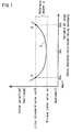
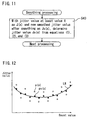
- a jitter value that is larger than a minimum value Jal obtained by past measurements by a reference amount ⁇ is set as the jitter threshold value J ⁇ th, and each jitter value (shown by the curve L in the drawing) are measured as the constant (SV) which establishes a servo characteristic is sequentially varied from a small value to a large value by a prescribed step, and of these jitter values a first variable value SVa corresponding to a first jitter value at point A in the drawing, which exceeds the jitter threshold value J ⁇ th, and a second variable value SVb corresponding to a second jitter value at point B in the drawing are determined, and further a third variable value SVc, which is for example an intermediate point between the first variable value SVa and the second variable value SVb, is set so as to optimize a constant value establishing the above-noted servo characteristic.
- SV constant
- the above-noted constant for establishing a servo characteristic corresponds to a relative distance or relative angle between the recording surface of the optical disc and an optical pickup.
- the above-noted reference amount ⁇ is, for example, a fixed value established based on an upper limit value (for example the jitter threshold value J ⁇ th for which a data error can be corrected when reading from the optical disc.
- the above-noted jitter threshold value J ⁇ th is set as a value that is an amount ⁇ greater than the minimum value of jitter Jal measured in the past, and if the fixed reference amount ⁇ is priorly set to a small amount so that the jitter threshold value J ⁇ th is a small value, it is possible to shorten the amount of time to measure the above-noted optimum value from the first variable value SVa and the second variable value SVb.
- the first variable value SVa and the second variable value SVb are determined from the jitter values measured while the variable SV is sequentially changed from a small value to a large value, if the above-noted jitter threshold value Jath is made a small value, the second variable value SVb is obtained particularly quickly, making it possible to quickly determine the above-noted third variable value SVc (optimum value).
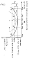
- the above-noted fixed reference amount is made a small value ⁇ d from the start, such as shown in Fig. 2, so that the jitter threshold value is a small value of J ⁇ dth, if the jitter value worsens, such as shown by the curve Ld in the drawing, there is a risk that it will not be possible to achieve a first variable value SVad and a second variable value SVbd sufficient to set the above-noted optimum value.
- the reference amount ⁇ is made a large amount ⁇ g at the start, so that the jitter threshold value is a large value J ⁇ gth, it is possible to obtain a first variable value and a second variable value sufficient for setting the above-noted optimum value.
- the jitter threshold value J ⁇ gth is used, even if a jitter variation D occurs suddenly, such as shown by the curve Ld in Fig.
- the fixed reference amount ⁇ is priorly set to a large amount ⁇ g so that the jitter threshold amount is a large amount J ⁇ gth
- the curve Lg in the drawing for example, excessive time is required for the measurement of the above-noted optimum value. That is, when the jitter value improves, the curve Lg in Fig. 2 not only exhibits a reduction in the jitter at the lowest part, but also a reduction in the amount of change in the jitter with respect to the amount of change in the variable values.
- EP 0 609 882 A1 discloses an automatic bias adjustment technique for a focus servo circuit.
- a signal is measured and the number of times in a 98 frame period that the signal deviates by a predetermined amount is determined for particular bias voltages.
- the minimum number of deviations is established from the measured values and a threshold number of deviations is set which is greater than the minimum by a predetermined percentage.
- Two bias voltages are measured when the measured number of deviations matches the threshold and the average of these two bias voltages is obtained, this average value being the automatic bias voltage.
- EP 0 840 295 A2 discloses an optical disc initialising system in which a focus offset value is varied in both the positive and negative directions in order to determine a point of minimum jitter.
- the present invention in view of the above-described problems, provides an optical disc apparatus as claimed in claim 1, a method as claimed in claim 5, a computer-readable recording medium recording a program as claimed in claim 9, and a program as claimed in claim 10, all for performing adjustment of a servo of an optical disc apparatus, whereby, for example, it is possible to quickly and accurately detect an optimum constant for establishing a servo characteristic, and to achieve good servo adjustment.
- An embodiment of the present invention establishes a minimum jitter value from jitter values measurement in correspondence to successively changed servo constants, multiplies this minimum jitter value by a prescribed ratio to set a jitter threshold value, establishes servo constants corresponding to at least two jitter values that are substantially equal to the jitter threshold value, and sets an optimum servo constant based on these servo constants.
- the minimum jitter value is a variable value because it is established by jitter values measured in correspondence with successively changed servo constants
- the jitter threshold value is a variable because it is established by multiplying the variable minimum jitter value by a prescribed ratio.
- the jitter threshold value is also set as a large value.
- the jitter threshold value is also set so as to be a small value.
- Fig. 3 shows the general configuration of an optical disc apparatus according to an embodiment in which the present invention is applied.
- an optical disc 50 is chucked by a chucking member (not shown in the drawing) provided on an end of a rotating shaft 51 of a spindle motor 52, and is rotationally driven by the spindle motor 52.
- An optical pickup 53 is made up of a laser light source, such as a laser diode, a system of optics, which collects and shines the laser light of the laser light source onto the recording surface of the optical disc 50 and which also guides light reflected from the recording surface to a light-receiving surface, an photo-electric conversion element such as a photodetector, having the light-receiving surface of a prescribed pattern and which converts a variable intensity of the reflected light guided thereto by the optics system to a voltage of level commensurate thereto, and a two-axis actuator (not shown in the drawing), which causes an objective lens 54 included in the optics system to move in directions parallel to and perpendicular to a recording surface of the optical disc 50.
- a laser light source such as a laser diode
- optics which collects and shines the laser light of the laser light source onto the recording surface of the optical disc 50 and which also guides light reflected from the recording surface to a light-receiving surface
- a slide feeding mechanism 57 which causes the optical pickup 53 to move in a radial direction with respect to the optical disc 50, and a skew adjustment mechanism 56, which adjusts the angle of the optical pickup 53 so that the laser beam emitted by the optical pickup 53 is perpendicularly incident to the recording surface of the optical disc 50.
- the slide feeding mechanism 57 is made up of, for example, a threaded mechanism made up of a rack extending in a radial direction with respect to the optical disc 50 and a gear that meshes with the rack, and a stepping motor or the like which causes the gear to rotate, this feeding mechanism being known and, therefore, not described in detail herein, the optical pickup 53 being provided on top of the above-noted rack.
- the above-noted skew adjustment mechanism 56 is made up by a skew angle changing mechanism, which causes the angle of the optical pickup 53 with respect to the optical disc 50 to change within a range from a reference position to a maximum feed position, above-described a stepping motor or the like serving as a source of drive for the skew angle changing mechanism.
- An output signal of the optical pickup 53 is input to a focus/tracking error signal detector block 77 and an RF compensation block 70.
- the RF compensation block 70 compensates the input signal level and frequency characteristics of the input signal from the optical pickup 53. That is, because the signal output from the optical pickup 53, affected by an MTF (modulation transfer function), does not exhibit a flat signal frequency characteristic, and because the level of this signal is not proper for subsequent-stage signal processing, it is necessary to perform this compensation, and the compensation block 70 performs this compensation.
- the compensation block 70 performs various compensation items, one item that will be discussed in connection with this embodiment of the present invention is that of boost compensation.
- Boost compensation is compensation so that amplification is done to bring the RF signal from the optical pickup 53 to a level that can be processed by the subsequent signal processing block 90. Details of this boost compensation are provided below.
- the degree of change in reflectivity with respect to a spatial position change is referred to as spatial frequency
- the size of the output signal from the optical pickup 53 changes in accordance with the spatial frequency.
- the MTF is this function expressed as an equation, and in general the higher is the spatial frequency, the smaller is the output signal, the output signal being zero at above a certain spatial frequency.
- the output signal of the RF compensation block 70 is input to the signal processing block 90, and is also input to a servo constant adjustment block 80 for the purpose of automatically adjusting a servo constant that establishes a servo characteristic in this embodiment. Details of the configuration and operation of this servo constant adjustment block 80 are provided below.
- a signal from the RF compensation block is binarized by a binarization section 71, and a demodular 72 performs signal demodulation processing corresponding to the signal modulation processing performed when recording was done onto the optical disc 50. Although it is not shown in the drawing, the demodulated signal is then subjected to error correction processing and decoding processing.
- a focus/tracking error signal detection block 77 detects a focus error signal caused, for example, by so-called astigmatism or the like from the output of the optical pickup 53, and detects a tracking error signal using, for example, the so-called push-pull method. These focus and tracking error signals are sent to a mechanism controller 190.
- the mechanism controller 190 controls a drive block 180, and performs control of the above-described servos for focusing, tracking, slide feeding, and skew of the optical pickup 53, and control of the rotating servo for the spindle motor 52 used for optical disc rotational drive. That is, the mechanism controller 190, based on the above-noted focus error signal and tracking error signal, performs control of a focus bias and tracking bias values that are output by a focus drive IC 59 and a tracking drive IC 60, causing a two-axis actuator of the above-noted optical pickup 53 to be driven, so as to adjust the focal point of the objective lens 54 on the recording surface of the optical disc 50, and so as to adjust the laser spot onto a desired track.
- the mechanism controller 190 controls a spindle motor drive signal output by a spindle drive IC 58, so as to rotationally drive the spindle motor 52 for rotationally driving the optical disc 50, thereby achieving either a fixed or a variable rotational speed for the optical disc 50.
- the mechanism controller 190 also controls a slide feeding drive IC 61 of the drive block 180, so that the stepping motor of the threaded mechanism is driven to rotate a gear, thereby causing the optical pickup 53 to move along a radial direction with respect to the optical disc 50.
- the mechanism controller 190 additionally controls the a skew drive IC 62 of the drive block 180, so as to drive a stepping motor of the skew angle adjustment mechanism, thereby establishing the positioning of the optical pickup 53 opposing the recording surface of the optical disc 50 so that it is at the center position.
- This center position is the center operating position set using a reference disc when the optical disc apparatus is manufactured.
- the chief constituent elements of the servo constant adjustment block 80 are a jitter measurement section 74, which measures the jitter from the output signal of the RF compensation block 70 as described later, a smoothing processing section 75, which smoothes the measured jitter as described later, and a servo characteristics setting section 76, which, from the above-noted smoothed jitter, sets a constant that establishes a servo characteristic.
- the servo constants set by the servo characteristics setting section 76 is a constant that, for example, establishes various servo characteristics, such as focus, tracking, skew, and RF signal boost compensation, and each of theses servo characteristics constants is sent to the corresponding RF compensation section 70 or the mechanism controller 190.
- a constant that establishes the RF signal boost compensation is sent from the above-noted servo characteristic setting section 76 to the RF compensation section 70, at which the RF signal boost compensation is performed in accordance with that constant.
- constants which establish servo characteristics such as skew and focus bias are set to the mechanism controller 190, at which the skew and focus bias control signals are generated in accordance with these constant values.
- the constants adjusted in the servo constant adjustment block 80 are constants that establish various servo characteristics, such as skew, focus bias, and RF signal boost compensation and the like, and in the following description of an embodiment, the constant for the RF signal boost compensation (hereinafter referred to as the boost value) is taken as being exemplary of these constants for the purpose of the description.
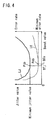
- the best signal characteristics are obtained when the error rate is the best.
- the jitter value is not necessarily the best. That is, as shown in Fig. 4, the boost value BTj corresponding to the point Pjb, at which jitter value is minimum on the jitter curve LJ is not necessarily the same as the boost value BTe corresponding to the point Peb at which the error rate is minimum on the error rate curve LE.
- one approach that can be envisioned is that of measuring the jitter value for each of a number of boost values and determining the relationship of the measured jitter values to the boost value, based on an experimentally obtained relationship between the jitter value and the error rate, predicting the boost value at which the error rate is best, and setting the boost value obtained from this prediction as the optimum constant for boost compensation.
- the above-noted prescribed ratio ⁇ is a ratio pre-determined for each servo adjustment item, and specific values thereof are described below.
- the jitter threshold value J ⁇ th obtained by adding a fixed reference amount ⁇ to a minimum jitter value Jal obtained by past measurements, such as described with reference to Fig. 1, as described above the a jitter value obtained by multiplying a minimum jitter value measured for each mounting or playback of the optical disc 50 by a prescribed ratio ⁇ is used as the jitter threshold value J ⁇ th. That is, in the case of this embodiment, the minimum jitter value is a variable value, and as a result the jitter threshold value, which is obtained by multiplying this minimum jitter value by a prescribed ratio ⁇ , is also a variable value.
- the jitter threshold value is also set as a large value, so that as described with regard to Fig. 2 even if the jitter worsens and a suddenly occurring variation D occurs, there is no erroneous detection occurring caused by that variation D, and as a result there is no erroneous setting of the boost value optimum value.
- the above-noted jitter threshold value J ⁇ th also is set so as to be a small value, so that, as described with regard to Fig. 2, even in the case in which the jitter improves, it is possible to reduce the time required to set the optimum boost value.
- a prescribe value ⁇ be added to the minimum jitter value obtained by measurement as in this embodiment, and this be set as the jitter threshold value.
- a prescribed value ⁇ is added to the minimum jitter value obtained by measurement, however, compared to the case such as this embodiment, in which the minimum jitter value is multiplied by a prescribed ratio ⁇ , the amount of change in the jitter threshold value with respect to a change in the minimum jitter value is small.
- boost constant adjustment block 80 of an optical disc apparatus for measuring the jitter from the RF signal, and for setting a constant (boost value) for obtaining the best boost compensation based on that jitter value is described below.
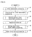
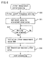
- Fig. 5 shows the general flow of processing in the procedure for adjusting the boost value in an optical disc apparatus according to this embodiment of the present invention.
- jitter measurement processing is first performed at step S1, and a setting such as the setting of the cutoff frequency or other initial value is made in response to the initial structure of the recording layer of the optical disc 50.
- boost value initialization is also performed of the boost value of the RF compensation block 70. Details of the jitter measurement performed at step S1 are described later, with reference being made to Fig. 4.
- step S2 being a step for plus-direction jitter measurement processing
- the boost value is stepwise increased by a prescribed step from a pre-established center boost value in the plus direction (direction of increasing the boost value)
- the jitter measurement section 74 the jitter values corresponding to each value of boost are measured, as the minimum jitter value is updated and the jitter threshold value is set, each jitter value, minimum jitter value, and jitter threshold value being stored into a RAM area for jitter measurement in the RAM 78. Details of the plus-direction jitter measurement processing at step S2 are described later, with references made to Fig. 7 and Fig. 8.
- step S3 as a step for minus-direction jitter measurement processing
- the boost value is stepwise decreased by a prescribed step from a pre-established center boost value in the minus direction (direction of decreasing the boost value)
- the jitter measurement section 74 the jitter values corresponding to each value of boost are measured, as the minimum jitter value is updated and the jitter threshold value is set, each jitter value, minimum jitter value, and jitter threshold value being stored into the RAM area for jitter measurement. Details of the minus-direction jitter measurement processing at step S3 are described later, with references made to Fig. 9 and Fig. 10.
- step S4 which performs smoothing processing
- the jitter values measured at the above steps by the jitter measurement section 74 are sent to the smoothing processing section 75, at which smoothing processing is performed so as to remove dispersion among the jitter values.
- this smoothing processing is not absolutely required, by performing smoothing processing it is possible to reduce the dispersion in jitter values. Details of the smoothing processing at step S4 are described later, with reference made to Fig. 9 and Fig. 10.
- step S5 processing is performed to establish an optimum boost value.
- the jitter values stored in the jitter measurement RAM and boost values corresponding to these jitter values are used to determine the optimum boost value, at which the error rate is minimum, at step S6, which performs boost value setting, the above-noted optimum boost value is set as a constant value for boost compensation in the RF compensation section 70. Details of the optimum boost value establishing processing at step S5 are described below with reference made to Fig. 13 and Fig. 14, and details of the boost value setting processing at step S6 are described below with reference made to Fig. 15.
- a setting is made of the cutoff frequency of a filter for the purpose of extracting a signal component from the above-noted RF signal.
- the servo characteristics setting section 76 initializes the boost value at the RF compensation block 70 to, for example, a center boost value that has been stored in an EEPROM 79 or the like beforehand.
- the jitter measurement section 74 waits a prescribed amount of waiting time (for example, 10 milliseconds), after which at step S13 the jitter measurement RAM area provided within the RAM 78 is initialized (to 0xfffh, where the suffixed h indicates hexadecimal notation).
- a prescribed amount of waiting time for example, 10 milliseconds
- the jitter measurement section 74 sets the minimum jitter value as the theoretical maximum value as an initial value.
- step S14 After the processing of step S14, the flow of processing proceeds to step S2 of Fig. 5.
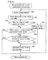
- the processing flow proceeds to plus-direction jitter measurement processing, at which point as the processing of step S20 the servo characteristics setting section 76 first causes the boost value to be stepwise increased by a prescribed step in the plus direction (direction that increases the boost value) from the initialized center boost value set at step S11 of Fig. 6. Simultaneously with this, as the processing of step S21 at the jitter measurement section 74 measures jitter values corresponding to each boost value set at prescribed steps, and the measurement jitter values are stored into a RAM area for measured jitter values. Details of the jitter measurement processing at step S20 are described later, with reference made to Fig. 7 and Fig. 8.
- the jitter measurement section 74 makes a judgment as to whether or not jitter values measured at each step of boost value are smaller than the minimum previous measured jitter value, and if the judgment result is "yes", as the processing of step S23 the measured jitter value is used to update the minimum jitter value, but if the judgment result is "no", the flow of processing proceeds to the plus-direction jitter measurement end-judgment processing at step S24 and thereafter.
- the servo characteristics setting section 76 makes a judgment whether or not the current boost value has reached a pre-determined value for the plus-direction boost value (for example, the maximum value at which boost compensation is possible). If the judgment is that this pre-determined value has not been reached, processing flow proceeds to step S25, and if the judgment is made that the pre-determined value has been reached, after returning the boost value to the center boost value at step S27, the processing flow proceeds to the minus-direction jitter measurement processing.
- a pre-determined value for the plus-direction boost value for example, the maximum value at which boost compensation is possible.
- the jitter measurement section 74 uses a jitter threshold value J ⁇ th determined by multiplying the jitter value determined as described above by a prescribed ratio ⁇ and makes a judgment as to whether or not the above measured jitter value exceeds this jitter threshold value three times in a row. If the judgment is that it has not exceeded the jitter threshold J ⁇ th value three times in a row, the processing flow proceeds to step S26. If the judgment is made, however, that the jitter value exceeded the jitter threshold value J ⁇ th three times in a row, the jitter measurement is stopped at step S27, and the flow of processing proceeds to the minus-direction jitter measurement processing. Details of the jitter measurement end judgment processing using the jitter threshold value J ⁇ th at step S25 are described later, with reference made to Fig. 8.
- the servo characteristics setting section 76 causes an increase of one prescribed step only in the boost value, after which return is made to the processing of step S20, from which point the plus-direction jitter measurement processing is repeated.
- step S30 the servo characteristics setting section 76 first causes the boost value to be stepwise decreased by a prescribed step in the minus direction (direction that decreases the boost value) from the initialized center boost value returned to at step S27 of Fig. 7. Simultaneously with this, as the processing of step S31 at the jitter measurement section 74 measures jitter values corresponding to each boost value set at prescribed steps, and the measurement jitter values are stored into a RAM area for measured jitter values. Details of the jitter measurement processing at step S30 are described later, with reference made to Fig. 9 and Fig. 10.
- the jitter measurement section 74 makes a judgment as to whether or not jitter values measured at each step of boost value are smaller than the minimum previous measured jitter value, and if the judgment result is "yes", as the processing of step S33 the measured jitter value is used to update the minimum jitter value, but if the judgment result is "no", the flow of processing proceeds to the plus-direction jitter measurement end-judgment processing at step S34 and thereafter.
- the servo characteristics setting section 76 makes a judgment whether or not the current boost value has reached a pre-determined value for the minus-direction boost value (for example, the minimum value at which boost compensation is possible). If the judgment is that this pre-determined value has not been reached, processing flow proceeds to step S35, and if the judgment is made that the pre-determined value has been reached, the flow of processing proceeds to the smoothing processing of step S24 in Fig. 5, which is the next processing to be performed.
- a pre-determined value for the minus-direction boost value for example, the minimum value at which boost compensation is possible.
- the jitter measurement section 74 uses a jitter threshold value J ⁇ th determined by multiplying the jitter value determined as described above by a prescribed ratio ⁇ and makes a judgment as to whether or not the above measured jitter value exceeds this jitter threshold value three times in a row. If the judgment is that it has not exceeded the jitter threshold J ⁇ th value three times in a row, the processing flow proceeds to step S36. If the judgment is made, however, that the jitter value exceeded the jitter threshold value J ⁇ th three times in a row, the flow of processing proceeds to the smoothing processing of step S4 of Fig. 3, which is the next processing to be performed. Details of the jitter measurement end judgment processing using the jitter threshold value J ⁇ th at step S35 are described later, with reference made to Fig. 10.
- step S35 the servo characteristics setting section 76 causes a reduction in the boost value by just one prescribed step, the flow of processing returning then to step S30, from which minus-direction jitter measurement processing is repeated.
- jitter measurement as performed at step S20 and step S30, for plus-direction and minus-direction jitter measurement processing, respectively, are described below.
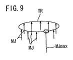
- a jitter measurement for a single boost value is performed as follows, under the assumption of normal-speed playback from the innermost circumference of the optical disc 50.
- the innermost disc radius is 24 mm
- the linear speed is 49 mm/s, the time required for one rotation of the disc being 43.2 s.
- jitter measurements are performed with one and the same boost value, this being measurement of 10 jitter values MJ for one and the same boost value at a time interval of 4 ms during one revolution of the disc.
- the arrow directions MJ for the jitter values shown in Fig. 9 indicate the jitter measurement points, and the lengths of the arrows indicate the size of the jitter values.
- the total of the 9 jitter values remaining after the maximum jitter value MJmax is eliminated is taken as the jitter value for that particular boost value.
- the reason that the maximum value is eliminated is that there are cases in which a flaw, for example, exits on the surface of the optical disc, this causing an anomalous extreme worsening of the jitter, and the elimination of the maximum jitter value is done to eliminate the influence of such changes in the jitter value caused by external disturbances.
- the jitter measurement (increasing and decreasing of the boost value) is terminated only when the measured jitter value exceeds the jitter threshold value three times in a row.
- a method is applied to remove chattering in the jitter value with respect to the boost value.
- the above-noted jitter threshold value J ⁇ th is determined, as described above, by multiplying a minimum jitter value, obtained by measurement, by a prescribed ratio ⁇ .
- the prescribed ratio ⁇ is a value obtained as an integer selected in steps of 10 over the range from 0 to 140, or a value that is 0.5 times the minimum jitter value.
- These prescribed ratios ⁇ are set from values pre-stored into, for example, the EEPROM 79, in response to the servo adjustment item.
- the smoothing processing section 75 takes the jitter value at some boost value x (where 0 ⁇ x ⁇ xmax) as J(x), and a new jitter value after smoothing as Js(x), using the Equations (1) to (3) presented below to calculate the new smoothed jitter value Js (x) , which is output as the jitter value after smoothing processing.
- Js(xmax) ⁇ J(xmax-1) + 3J(xmax) ⁇ /4
- Equation (1) is the equation used to determine a new post-smoothing jitter value Js(0) corresponding to a boost value of 0, which is the minimum boost value
- Equation (2) is the equation used to determine a new post-smoothing jitter value Js (x) corresponding to a boost value of x, which corresponds to the boost values after eliminating the minimum boost value 0 and the maximum boost value xmax
- Equation (3) is the equation used to determine a new post-smoothing jitter value Js (xmax) corresponding to a boost value of xmax, which is the maximum boost value.
- the 3J(0) coefficient 3 in Equation (1), the 2J(x) coefficient 2 in Equation (2), and the 3J(xmax) coefficient 3 in Equation (3) are weighting coefficients, the denominator 4 in each case being the number of data.
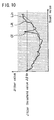
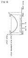
- Fig. 12 shows the boost value x, plots of plots p(x) of the jitter value J(x) before smoothing, plots ps(x) of the jitter values Js(x) after smoothing, and an approximated curve LR obtained by the method of least squares for each of the plotted data points.
- the pre-smoothing plotted points p (x) exhibit a large amount of jitter value dispersion.
- the post-smoothing plotted points ps (x) have only a small dispersion in jitter value.
- the servo characteristics setting section 76 sets the boost value corresponding to the smaller first jitter value A ⁇ exceeding the j ⁇ th threshold as the first boost value BTmin, and sets the larger second jitter value B ⁇ exceeding the j ⁇ th threshold as the second boost value BTmax.
- the servo characteristics setting section 76 establishes the optimum boost value BTbest, at which it is thought that the error rate will be the minimum, using the first boost value BTmin, the second boost value BTmax, and a prescribed coefficient value r that is pre-stored in the EEPROM 79, applying the Equation (4) given below.
- BTbest BTmin + (BTmax-BTmin)r/16
- the coefficient r is one of integers from 0 to 15 prepared beforehand in the EEPROM 79, for the purpose of establishing the boost value at which point is to be taken as the optimum boost value BTbest, in the case in which the span between the first boost value BTmin and the second boost value BTmax is divided by 16.
- This coefficient r is selected in response to the various adjustment items and, for example, in the case in which the central point boost value between the first and second boost values BTmin and BTmax is to be taken as the optimum boost value BTbest, r would be 8.
- Equation (4) corresponds to the number of divisions taken between the first and second boost values BTmin and BTmax, as shown in Fig. 14.
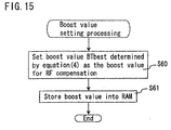
- step S6 of Fig. 5 After establishing the optimum boost value BTbest as described above, the processing flow proceeds to the boost value setting processing of step S6 of Fig. 5.
- the servo characteristics setting section 76 sets the optimum boost value BTbest determined by the Equation (4) as the boost value in the RF compensation block 70.
- the servo characteristics setting section 76 executes step S61 to store this boost value into the RAM 78.
- the minimum jitter value is measured each time the optical disc 50 is mounted or each time playback or the like is performed, this minimum jitter value being multiplied by a prescribed ratio ⁇ to establish the jitter threshold value J ⁇ th, and a first boost value BTmin and a second boost value BTmax exceeding this jitter threshold value J ⁇ th are applied to a prescribed equation so as to set the optimum boost value BTbest, the result being that it is possible to quickly and accurately detect the optimum boost value BTbest for, for example, the RF compensation, thereby enabling the achievement of good boost compensation.
Landscapes
- Optical Recording Or Reproduction (AREA)
- Moving Of The Head To Find And Align With The Track (AREA)
Claims (10)
- Appareil à disque optique dans lequel un faisceau laser provenant d'une tête de lecture optique (53) est utilisable pour projeter de la lumière sur une surface d'enregistrement d'un disque optique (50), et dans lequel de l'information est lue sur le disque optique, l'appareil à disque optique comprenant :caractérisé :une section (76) de modification de constante d'asservissement utilisable pour modifier de manière successive une constante d'asservissement ;une section (74) de mesure d'instabilité utilisable pour mesurer une valeur d'instabilité d'un signal de sortie provenant de la tête de lecture optique ;une section de mesure d'instabilité minimale, utilisable pour établir une valeur d'instabilité minimale à partir de chaque valeur d'instabilité mesurée en réponse à une constante d'asservissement modifiée de manière successive ;une section de fixation de valeur de seuil d'instabilité, utilisable pour fixer une valeur (Jβth) de seuil d'instabilité en multipliant la valeur d'instabilité minimale par un rapport imposé (β) ;une section (76) d'établissement de constante d'asservissement qui, à partir des valeurs mesurées d'instabilité en correspondance avec une constante d'asservissement modifiée de manière successive, est utilisable pour fixer au moins deux valeurs d'instabilité pratiquement égales à la valeur (Jβth) de seuil d'instabilité, et pour établir une constante d'asservissement correspondant à chacune des valeurs d'instabilité fixées ;une section (76) de fixation de constante d'asservissement optimale, qui est utilisable pour fixer une constante d'asservissement optimale en se basant sur la constante d'asservissement correspondant à chacune des valeurs d'instabilité fixées ;l'appareil à disque optique comprenant en outre :en ce qu'une section (76) d'initialisation de constante d'asservissement est utilisable pour fixer la constante d'asservissement à une valeur initiale imposée ;en ce que la section (76) de modification de constante d'asservissement est utilisable pour modifier de manière successive une constante d'asservissement à partir de la valeur initiale imposée dans un sens dans lequel la constante d'asservissement est augmentée et dans un sens dans lequel la constante d'asservissement est diminuée ;en ce que la section (76) d'établissement de constante d'asservissement est utilisable pour terminer l'opération de modification de la constante d'asservissement lorsque la constante d'asservissement atteint une valeur préétablie ; eten ce que la section (74) de mesure d'instabilité est utilisable pour terminer l'opération de mesure d'instabilité lorsque la valeur d'instabilité excède la valeur de seuil d'instabilité un nombre imposé de fois dans une rangée ;dans lequel la section (76) d'établissement de constante d'asservissement est utilisable pour fixer lesdites au moins deux valeurs d'instabilité prises parmi chaque valeur d'instabilité après le lissage.une section (75) de lissage, qui est utilisable pour lisser la dispersion dans chaque valeur d'instabilité mesurée en correspondance avec la constante d'asservissement modifiée de manière successive ; et
- Appareil à disque optique selon la revendication 1, dans lequel la section (74) de mesure d'instabilité est utilisable pour mesurer une pluralité de valeurs d'instabilité pour une unique constante d'asservissement, et à partir de la pluralité de valeurs d'instabilité est utilisable pour fixer, en tant que valeur d'instabilité correspondant à l'unique constante d'asservissement, un total de chaque valeur d'instabilité après en avoir éliminé la valeur maximale.
- Appareil à disque optique selon la revendication 1 ou 2, dans lequel la section (76) de modification de constante d'asservissement est utilisable pour fixer, en tant que constante d'asservissement, une valeur de compensation dans le but de compenser un niveau d'un signal de sortie provenant de la tête de lecture optique.
- Appareil à disque optique selon l'une quelconque des revendications précédentes, dans lequel le rapport (β) _imposé est une valeur obtenue sous forme d'un nombre entier choisi par pas de 10 sur une plage allant de 0 à 140, ou une valeur qui est 0,5 fois la valeur d'instabilité minimale.
- Procédé de réglage d'asservissement d'une caractéristique d'asservissement dans un appareil à disque optique dans lequel un faisceau laser provenant d'une tête de lecture optique (53) est projeté à une surface d'enregistrement d'un disque optique (50), et dans lequel de l'information est lue sur le disque optique, le procédé comprenant les étapes consistant :caractérisé par le fait :à modifier de manière successive une constante d'asservissement ;à mesurer une valeur d'instabilité d'un signal de sortie provenant de la tête de lecture optique (53) ;à établir une valeur d'instabilité minimale à partir de chaque valeur d'instabilité mesurée en correspondance avec la constante d'asservissement modifiée de manière successive ;à multiplier la valeur d'instabilité minimale par un rapport imposé (β) et à fixer une valeur (Jβth) de seuil d'instabilité ;à fixer au moins deux valeurs d'instabilité, pratiquement égales à la valeur (Jβth) de seuil d'instabilité, prises parmi chaque valeur d'instabilité mesurée en correspondance avec la constante d'asservissement modifiée de manière successive et à établir une constante d'asservissement correspondant à chacune des valeurs d'instabilité fixées ;à fixer une constante d'asservissement optimale en se basant sur la constante d'asservissement correspondant à chacune des valeurs d'instabilité fixées ;de fixer la constante d'asservissement à une valeur initiale imposée ;de modifier de manière successive la constante d'asservissement à partir de la valeur initiale imposée dans un sens dans lequel la constante d'asservissement est augmentée (S2) et dans un sens dans lequel la constante d'asservissement est diminuée (S3) ;de terminer l'opération de modification de constante d'asservissement lorsque la constante d'asservissement atteint une valeur préétablie ;de terminer l'opération de mesure d'instabilité lorsque la valeur d'instabilité excède la valeur (Jβth) de seuil d'instabilité un nombre imposé de fois dans une rangée (S25 ; S35) ;de lisser (S4) la dispersion de chaque valeur d'instabilité mesurée en correspondance avec une constante d'asservissement modifiée de manière successive ; etde fixer lesdites au moins deux valeurs d'instabilité prises parmi chaque valeur d'instabilité après le lissage.
- Procédé de réglage d'asservissement selon la revendication 5, comprenant en outre les étapes consistant :à mesurer une pluralité de valeurs d'instabilité pour une unique constante d'asservissement ; età fixer, comme valeur d'instabilité correspondant à l'unique constante d'asservissement, un total de chaque valeur d'instabilité après en avoir éliminé la valeur maximale.
- Procédé de réglage d'asservissement selon la revendication 5 ou 6, comprenant en outre une étape consistant à fixer, comme constante d'asservissement, d'une valeur de compensation pour compenser un niveau de sortie d'un signal de sortie provenant de la tête de lecture optique.
- Procédé de réglage d'asservissement selon l'une quelconque des revendications 5 à 7, comprenant en outre l'étape consistant à obtenir le rapport imposé (β) sous forme d'un nombre entier choisi en pas de 10 sur une plage allant de 0 à 140, ou une valeur qui est 0,5 fois la valeur de l'instabilité minimale.
- Support d'enregistrement lisible en ordinateur sur lequel est enregistré un programme de réglage d'asservissement, le programme de réglage d'asservissement étant utilisable pour mettre en oeuvre le procédé tel que revendiqué dans l'une quelconque des revendications 5 à 8 lorsque le programme de réglage d'asservissement est exécuté sur un ordinateur.
- Programme de réglage d'asservissement qui est utilisable pour mettre en oeuvre le procédé tel que revendiqué dans l'une quelconque des revendications 5 à 8 lorsque le programme de réglage d'asservissement est exécuté sur un ordinateur.
Applications Claiming Priority (4)
| Application Number | Priority Date | Filing Date | Title |
|---|---|---|---|
| JP2000387528 | 2000-12-20 | ||
| JP2000387528 | 2000-12-20 | ||
| JP2001372784A JP3576137B2 (ja) | 2000-12-20 | 2001-12-06 | 光ディスク装置、光ディスク装置のサーボ調整方法、光ディスクのサーボ調整プログラム、及び光ディスクのサーボ調整プログラムを記録したコンピュータ読み取り可能な記録媒体 |
| JP2001372784 | 2001-12-06 |
Publications (2)
| Publication Number | Publication Date |
|---|---|
| EP1217618A1 EP1217618A1 (fr) | 2002-06-26 |
| EP1217618B1 true EP1217618B1 (fr) | 2004-03-03 |
Family
ID=26606199
Family Applications (1)
| Application Number | Title | Priority Date | Filing Date |
|---|---|---|---|
| EP01310444A Expired - Lifetime EP1217618B1 (fr) | 2000-12-20 | 2001-12-13 | Appareil à disques optiques et méthode d'ajustage de son système d'asservissement |
Country Status (5)
| Country | Link |
|---|---|
| US (1) | US6928034B2 (fr) |
| EP (1) | EP1217618B1 (fr) |
| JP (1) | JP3576137B2 (fr) |
| AT (1) | ATE261174T1 (fr) |
| DE (1) | DE60102207T2 (fr) |
Families Citing this family (6)
| Publication number | Priority date | Publication date | Assignee | Title |
|---|---|---|---|---|
| KR100457518B1 (ko) * | 2002-05-07 | 2004-11-17 | 삼성전자주식회사 | 틸트 보정 장치 및 방법 |
| KR20040009799A (ko) * | 2002-07-25 | 2004-01-31 | 삼성전자주식회사 | 지터 궤환을 이용한 틸트 보정 방법 및 그 장치 |
| KR100652951B1 (ko) * | 2004-06-10 | 2006-12-06 | 삼성전자주식회사 | 스큐 보정이 가능한 광디스크 장치 및 그 방법 |
| JP4551883B2 (ja) * | 2005-04-28 | 2010-09-29 | パナソニック株式会社 | フォーカス制御調整方法および光ディスク装置 |
| JP2009146529A (ja) * | 2007-12-17 | 2009-07-02 | Sharp Corp | サーボパラメータの検出方法およびそれを利用した光ピックアップ装置 |
| WO2010101000A1 (fr) * | 2009-03-02 | 2010-09-10 | 株式会社ソニー・コンピュータエンタテインメント | Dispositif à disque optique, procédé de commande adapté, programme et support d'enregistrement d'informations |
Family Cites Families (16)
| Publication number | Priority date | Publication date | Assignee | Title |
|---|---|---|---|---|
| JPH06231477A (ja) | 1993-02-05 | 1994-08-19 | Sony Corp | フォーカスサーボ回路 |
| US5663942A (en) * | 1994-05-02 | 1997-09-02 | Matsushita Electric Industrial Co., Ltd. | Jitter measurement apparatus detecting amplitude of phase errors between information signal and synchronized clock signal |
| US5898654A (en) * | 1994-07-14 | 1999-04-27 | Matsushita Electric Industrial Co., Ltd. | Optical disk and optical disk apparatus having a predetermined pattern of marks on tracks such that a reproduced signal is caused to jitter |
| JP3489271B2 (ja) * | 1995-06-16 | 2004-01-19 | ソニー株式会社 | ディスク駆動装置および傾き調整方法 |
| US5848036A (en) * | 1996-06-20 | 1998-12-08 | Matsushita Electric Industrial Co., Ltd. | Optical disk drive equipped with waveform equalizer and focus adjustment circuit |
| JP3678509B2 (ja) * | 1996-09-04 | 2005-08-03 | クラリオン株式会社 | フォーカスサーボ回路 |
| JPH10134372A (ja) * | 1996-10-31 | 1998-05-22 | Sony Corp | 再生装置および方法 |
| JP3915163B2 (ja) * | 1997-03-18 | 2007-05-16 | ソニー株式会社 | ディジタル信号再生回路 |
| JPH11219566A (ja) * | 1997-11-28 | 1999-08-10 | Matsushita Electric Ind Co Ltd | ディジタルデータ再生装置および再生信号二値化レベル補正方法 |
| JPH11273097A (ja) * | 1998-03-17 | 1999-10-08 | Sony Corp | フォーカスサーボ回路および光ディスク記録再生装置 |
| JP2000149282A (ja) * | 1998-11-12 | 2000-05-30 | Clarion Co Ltd | フォーカスサーボ回路 |
| JP2000293875A (ja) * | 1999-04-07 | 2000-10-20 | Sony Corp | 光ディスク装置 |
| US6430119B1 (en) * | 1999-05-10 | 2002-08-06 | Matsushita Electric Industrial Co., Ltd. | Optical disk drive apparatus capable of searching an optimum target position |
| JP2001110059A (ja) * | 1999-10-05 | 2001-04-20 | Yamaha Corp | 光ディスク再生方法および光ディスク再生装置 |
| JP2001126261A (ja) * | 1999-10-29 | 2001-05-11 | Yamaha Corp | 光ディスク再生装置 |
| US6680887B2 (en) * | 2000-05-15 | 2004-01-20 | Matsushita Electric Industrial Co., Ltd. | Optical disk apparatus and PLL circuit |
-
2001
- 2001-12-06 JP JP2001372784A patent/JP3576137B2/ja not_active Expired - Fee Related
- 2001-12-13 AT AT01310444T patent/ATE261174T1/de not_active IP Right Cessation
- 2001-12-13 EP EP01310444A patent/EP1217618B1/fr not_active Expired - Lifetime
- 2001-12-13 DE DE60102207T patent/DE60102207T2/de not_active Expired - Lifetime
- 2001-12-17 US US10/024,589 patent/US6928034B2/en not_active Expired - Lifetime
Also Published As
| Publication number | Publication date |
|---|---|
| ATE261174T1 (de) | 2004-03-15 |
| US6928034B2 (en) | 2005-08-09 |
| EP1217618A1 (fr) | 2002-06-26 |
| DE60102207T2 (de) | 2005-02-03 |
| JP2002251754A (ja) | 2002-09-06 |
| JP3576137B2 (ja) | 2004-10-13 |
| DE60102207D1 (de) | 2004-04-08 |
| US20040008608A1 (en) | 2004-01-15 |
Similar Documents
| Publication | Publication Date | Title |
|---|---|---|
| KR100426718B1 (ko) | 광 디스크 드라이브장치 | |
| EP1217618B1 (fr) | Appareil à disques optiques et méthode d'ajustage de son système d'asservissement | |
| US7102975B2 (en) | Optical disk read/write apparatus and writing method | |
| US6252835B1 (en) | Apparatus for automatically adjusting focus offset and method thereof in a disc player | |
| US6876614B2 (en) | Tilt control device and method | |
| KR20030027848A (ko) | 광 디스크 재생 장치에 이용되는 서보 회로 및 그 서보 방법 | |
| JP3714458B2 (ja) | 光学式ディスクプレーヤのサーボ制御装置 | |
| US7894313B2 (en) | Optical disc recording and reproducing apparatus | |
| TWI293174B (en) | Optical-disc driving apparatus, optical-disc driving method, storage medium | |
| KR20040070749A (ko) | 광디스크 종류 판별장치 및 방법 | |
| KR20020051871A (ko) | 광 디스크 장치 및 광 디스크 장치의 레이저 파워 조정 방법 | |
| US7915569B2 (en) | Method for calibrating focus level on a light scribe disc | |
| US7558165B2 (en) | Disc drive calibration with forced track traversing signal | |
| KR100722591B1 (ko) | 광픽업에서의 광축 틀어짐 보상방법 | |
| US7903515B2 (en) | Optical disc drive | |
| JP3580721B2 (ja) | トラッキング調整装置 | |
| KR100556495B1 (ko) | 광 디스크 기록 재생 방법 및 장치 | |
| KR100588171B1 (ko) | 광픽업의 광축 방향 조정방법 | |
| KR100233652B1 (ko) | 광디스크 재생기록장치의 포커스바이어스 조정방법 | |
| JP4699423B2 (ja) | 光ディスク装置 | |
| JP3189651B2 (ja) | 光ディスク装置 | |
| JP2003317288A (ja) | 光ディスク装置及びディスクチルト検出方法 | |
| KR100233651B1 (ko) | 광디스크 재생기록장치의 포커스바이어스 조정방법 | |
| US20090274018A1 (en) | Recording device and radial offset calibration method | |
| JP2002092907A (ja) | 光ディスク装置 |
Legal Events
| Date | Code | Title | Description |
|---|---|---|---|
| PUAI | Public reference made under article 153(3) epc to a published international application that has entered the european phase |
Free format text: ORIGINAL CODE: 0009012 |
|
| AK | Designated contracting states |
Kind code of ref document: A1 Designated state(s): AT BE CH CY DE DK ES FI FR GB GR IE IT LI LU MC NL PT SE TR |
|
| AX | Request for extension of the european patent |
Free format text: AL;LT;LV;MK;RO;SI |
|
| 17P | Request for examination filed |
Effective date: 20020729 |
|
| 17Q | First examination report despatched |
Effective date: 20020926 |
|
| AKX | Designation fees paid |
Designated state(s): AT BE CH CY DE DK ES FI FR GB GR IE IT LI LU MC NL PT SE TR |
|
| GRAP | Despatch of communication of intention to grant a patent |
Free format text: ORIGINAL CODE: EPIDOSNIGR1 |
|
| GRAS | Grant fee paid |
Free format text: ORIGINAL CODE: EPIDOSNIGR3 |
|
| GRAA | (expected) grant |
Free format text: ORIGINAL CODE: 0009210 |
|
| AK | Designated contracting states |
Kind code of ref document: B1 Designated state(s): AT BE CH CY DE DK ES FI FR GB GR IE IT LI LU MC NL PT SE TR |
|
| PG25 | Lapsed in a contracting state [announced via postgrant information from national office to epo] |
Ref country code: BE Free format text: LAPSE BECAUSE OF FAILURE TO SUBMIT A TRANSLATION OF THE DESCRIPTION OR TO PAY THE FEE WITHIN THE PRESCRIBED TIME-LIMIT Effective date: 20040303 Ref country code: IT Free format text: LAPSE BECAUSE OF FAILURE TO SUBMIT A TRANSLATION OF THE DESCRIPTION OR TO PAY THE FEE WITHIN THE PRE;WARNING: LAPSES OF ITALIAN PATENTS WITH EFFECTIVE DATE BEFORE 2007 MAY HAVE OCCURRED AT ANY TIME BEFORE 2007. THE CORRECT EFFECTIVE DATE MAY BE DIFFERENT FROM THE ONE RECORDED.SCRIBED TIME-LIMIT Effective date: 20040303 Ref country code: TR Free format text: LAPSE BECAUSE OF FAILURE TO SUBMIT A TRANSLATION OF THE DESCRIPTION OR TO PAY THE FEE WITHIN THE PRESCRIBED TIME-LIMIT Effective date: 20040303 Ref country code: LI Free format text: LAPSE BECAUSE OF FAILURE TO SUBMIT A TRANSLATION OF THE DESCRIPTION OR TO PAY THE FEE WITHIN THE PRESCRIBED TIME-LIMIT Effective date: 20040303 Ref country code: CH Free format text: LAPSE BECAUSE OF FAILURE TO SUBMIT A TRANSLATION OF THE DESCRIPTION OR TO PAY THE FEE WITHIN THE PRESCRIBED TIME-LIMIT Effective date: 20040303 Ref country code: CY Free format text: LAPSE BECAUSE OF FAILURE TO SUBMIT A TRANSLATION OF THE DESCRIPTION OR TO PAY THE FEE WITHIN THE PRESCRIBED TIME-LIMIT Effective date: 20040303 Ref country code: NL Free format text: LAPSE BECAUSE OF FAILURE TO SUBMIT A TRANSLATION OF THE DESCRIPTION OR TO PAY THE FEE WITHIN THE PRESCRIBED TIME-LIMIT Effective date: 20040303 Ref country code: FI Free format text: LAPSE BECAUSE OF FAILURE TO SUBMIT A TRANSLATION OF THE DESCRIPTION OR TO PAY THE FEE WITHIN THE PRESCRIBED TIME-LIMIT Effective date: 20040303 Ref country code: ES Free format text: LAPSE BECAUSE OF FAILURE TO SUBMIT A TRANSLATION OF THE DESCRIPTION OR TO PAY THE FEE WITHIN THE PRESCRIBED TIME-LIMIT Effective date: 20040303 Ref country code: AT Free format text: LAPSE BECAUSE OF FAILURE TO SUBMIT A TRANSLATION OF THE DESCRIPTION OR TO PAY THE FEE WITHIN THE PRESCRIBED TIME-LIMIT Effective date: 20040303 Ref country code: FR Free format text: LAPSE BECAUSE OF FAILURE TO SUBMIT A TRANSLATION OF THE DESCRIPTION OR TO PAY THE FEE WITHIN THE PRESCRIBED TIME-LIMIT Effective date: 20040303 |
|
| REG | Reference to a national code |
Ref country code: GB Ref legal event code: FG4D |
|
| REG | Reference to a national code |
Ref country code: CH Ref legal event code: EP |
|
| REG | Reference to a national code |
Ref country code: IE Ref legal event code: FG4D |
|
| REF | Corresponds to: |
Ref document number: 60102207 Country of ref document: DE Date of ref document: 20040408 Kind code of ref document: P |
|
| PG25 | Lapsed in a contracting state [announced via postgrant information from national office to epo] |
Ref country code: GR Free format text: LAPSE BECAUSE OF FAILURE TO SUBMIT A TRANSLATION OF THE DESCRIPTION OR TO PAY THE FEE WITHIN THE PRESCRIBED TIME-LIMIT Effective date: 20040603 Ref country code: SE Free format text: LAPSE BECAUSE OF FAILURE TO SUBMIT A TRANSLATION OF THE DESCRIPTION OR TO PAY THE FEE WITHIN THE PRESCRIBED TIME-LIMIT Effective date: 20040603 Ref country code: DK Free format text: LAPSE BECAUSE OF FAILURE TO SUBMIT A TRANSLATION OF THE DESCRIPTION OR TO PAY THE FEE WITHIN THE PRESCRIBED TIME-LIMIT Effective date: 20040603 |
|
| NLV1 | Nl: lapsed or annulled due to failure to fulfill the requirements of art. 29p and 29m of the patents act | ||
| REG | Reference to a national code |
Ref country code: CH Ref legal event code: PL |
|
| PG25 | Lapsed in a contracting state [announced via postgrant information from national office to epo] |
Ref country code: IE Free format text: LAPSE BECAUSE OF NON-PAYMENT OF DUE FEES Effective date: 20041213 Ref country code: LU Free format text: LAPSE BECAUSE OF NON-PAYMENT OF DUE FEES Effective date: 20041213 |
|
| PG25 | Lapsed in a contracting state [announced via postgrant information from national office to epo] |
Ref country code: MC Free format text: LAPSE BECAUSE OF NON-PAYMENT OF DUE FEES Effective date: 20041231 |
|
| PLBE | No opposition filed within time limit |
Free format text: ORIGINAL CODE: 0009261 |
|
| STAA | Information on the status of an ep patent application or granted ep patent |
Free format text: STATUS: NO OPPOSITION FILED WITHIN TIME LIMIT |
|
| EN | Fr: translation not filed | ||
| 26N | No opposition filed |
Effective date: 20041206 |
|
| REG | Reference to a national code |
Ref country code: IE Ref legal event code: MM4A |
|
| PG25 | Lapsed in a contracting state [announced via postgrant information from national office to epo] |
Ref country code: PT Free format text: LAPSE BECAUSE OF NON-PAYMENT OF DUE FEES Effective date: 20040803 |
|
| PGFP | Annual fee paid to national office [announced via postgrant information from national office to epo] |
Ref country code: DE Payment date: 20191203 Year of fee payment: 19 |
|
| PGFP | Annual fee paid to national office [announced via postgrant information from national office to epo] |
Ref country code: GB Payment date: 20191213 Year of fee payment: 19 |
|
| REG | Reference to a national code |
Ref country code: DE Ref legal event code: R119 Ref document number: 60102207 Country of ref document: DE |
|
| GBPC | Gb: european patent ceased through non-payment of renewal fee |
Effective date: 20201213 |
|
| PG25 | Lapsed in a contracting state [announced via postgrant information from national office to epo] |
Ref country code: GB Free format text: LAPSE BECAUSE OF NON-PAYMENT OF DUE FEES Effective date: 20201213 Ref country code: DE Free format text: LAPSE BECAUSE OF NON-PAYMENT OF DUE FEES Effective date: 20210701 |