EP1215347B1 - Verfahren zum Einbauen und Spannen eines freigespannten Zugglieds, sowie Verankerungsvorrichtung zum Durchführen des Verfahrens - Google Patents
Verfahren zum Einbauen und Spannen eines freigespannten Zugglieds, sowie Verankerungsvorrichtung zum Durchführen des Verfahrens Download PDFInfo
- Publication number
- EP1215347B1 EP1215347B1 EP01128712A EP01128712A EP1215347B1 EP 1215347 B1 EP1215347 B1 EP 1215347B1 EP 01128712 A EP01128712 A EP 01128712A EP 01128712 A EP01128712 A EP 01128712A EP 1215347 B1 EP1215347 B1 EP 1215347B1
- Authority
- EP
- European Patent Office
- Prior art keywords
- anchoring
- individual elements
- tensioning
- anchor plate
- plastic
- Prior art date
- Legal status (The legal status is an assumption and is not a legal conclusion. Google has not performed a legal analysis and makes no representation as to the accuracy of the status listed.)
- Expired - Lifetime
Links
- 238000004873 anchoring Methods 0.000 title claims abstract description 38
- 238000000034 method Methods 0.000 title claims abstract description 25
- 210000002435 tendon Anatomy 0.000 title claims description 6
- 229920003023 plastic Polymers 0.000 claims abstract description 25
- 239000004033 plastic Substances 0.000 claims abstract description 25
- 229910000831 Steel Inorganic materials 0.000 claims abstract description 11
- 239000010959 steel Substances 0.000 claims abstract description 11
- 230000003247 decreasing effect Effects 0.000 claims 1
- 230000000452 restraining effect Effects 0.000 claims 1
- 238000009435 building construction Methods 0.000 abstract 1
- 239000004698 Polyethylene Substances 0.000 description 24
- 229920000573 polyethylene Polymers 0.000 description 24
- 238000005260 corrosion Methods 0.000 description 5
- 230000007797 corrosion Effects 0.000 description 5
- 238000006073 displacement reaction Methods 0.000 description 4
- 125000006850 spacer group Chemical group 0.000 description 4
- 238000007789 sealing Methods 0.000 description 3
- 239000011248 coating agent Substances 0.000 description 2
- 238000000576 coating method Methods 0.000 description 2
- 230000006835 compression Effects 0.000 description 2
- 238000007906 compression Methods 0.000 description 2
- 239000004519 grease Substances 0.000 description 2
- 238000009434 installation Methods 0.000 description 2
- 239000000463 material Substances 0.000 description 2
- 230000000149 penetrating effect Effects 0.000 description 2
- 150000001875 compounds Chemical class 0.000 description 1
- 238000010276 construction Methods 0.000 description 1
- 230000001419 dependent effect Effects 0.000 description 1
- 238000011161 development Methods 0.000 description 1
- 230000018109 developmental process Effects 0.000 description 1
- 238000002347 injection Methods 0.000 description 1
- 239000007924 injection Substances 0.000 description 1
- -1 polyethylene Polymers 0.000 description 1
- 230000007704 transition Effects 0.000 description 1
Images


Classifications
-
- E—FIXED CONSTRUCTIONS
- E01—CONSTRUCTION OF ROADS, RAILWAYS, OR BRIDGES
- E01D—CONSTRUCTION OF BRIDGES, ELEVATED ROADWAYS OR VIADUCTS; ASSEMBLY OF BRIDGES
- E01D11/00—Suspension or cable-stayed bridges
-
- E—FIXED CONSTRUCTIONS
- E04—BUILDING
- E04C—STRUCTURAL ELEMENTS; BUILDING MATERIALS
- E04C5/00—Reinforcing elements, e.g. for concrete; Auxiliary elements therefor
- E04C5/08—Members specially adapted to be used in prestressed constructions
- E04C5/12—Anchoring devices
- E04C5/122—Anchoring devices the tensile members are anchored by wedge-action
-
- E—FIXED CONSTRUCTIONS
- E04—BUILDING
- E04G—SCAFFOLDING; FORMS; SHUTTERING; BUILDING IMPLEMENTS OR AIDS, OR THEIR USE; HANDLING BUILDING MATERIALS ON THE SITE; REPAIRING, BREAKING-UP OR OTHER WORK ON EXISTING BUILDINGS
- E04G21/00—Preparing, conveying, or working-up building materials or building elements in situ; Other devices or measures for constructional work
- E04G21/12—Mounting of reinforcing inserts; Prestressing
-
- E—FIXED CONSTRUCTIONS
- E04—BUILDING
- E04G—SCAFFOLDING; FORMS; SHUTTERING; BUILDING IMPLEMENTS OR AIDS, OR THEIR USE; HANDLING BUILDING MATERIALS ON THE SITE; REPAIRING, BREAKING-UP OR OTHER WORK ON EXISTING BUILDINGS
- E04G21/00—Preparing, conveying, or working-up building materials or building elements in situ; Other devices or measures for constructional work
- E04G21/12—Mounting of reinforcing inserts; Prestressing
- E04G21/121—Construction of stressing jacks
-
- Y—GENERAL TAGGING OF NEW TECHNOLOGICAL DEVELOPMENTS; GENERAL TAGGING OF CROSS-SECTIONAL TECHNOLOGIES SPANNING OVER SEVERAL SECTIONS OF THE IPC; TECHNICAL SUBJECTS COVERED BY FORMER USPC CROSS-REFERENCE ART COLLECTIONS [XRACs] AND DIGESTS
- Y10—TECHNICAL SUBJECTS COVERED BY FORMER USPC
- Y10T—TECHNICAL SUBJECTS COVERED BY FORMER US CLASSIFICATION
- Y10T24/00—Buckles, buttons, clasps, etc.
- Y10T24/39—Cord and rope holders
- Y10T24/3909—Plural-strand cord or rope
-
- Y—GENERAL TAGGING OF NEW TECHNOLOGICAL DEVELOPMENTS; GENERAL TAGGING OF CROSS-SECTIONAL TECHNOLOGIES SPANNING OVER SEVERAL SECTIONS OF THE IPC; TECHNICAL SUBJECTS COVERED BY FORMER USPC CROSS-REFERENCE ART COLLECTIONS [XRACs] AND DIGESTS
- Y10—TECHNICAL SUBJECTS COVERED BY FORMER USPC
- Y10T—TECHNICAL SUBJECTS COVERED BY FORMER US CLASSIFICATION
- Y10T29/00—Metal working
- Y10T29/49—Method of mechanical manufacture
- Y10T29/49826—Assembling or joining
- Y10T29/49863—Assembling or joining with prestressing of part
-
- Y—GENERAL TAGGING OF NEW TECHNOLOGICAL DEVELOPMENTS; GENERAL TAGGING OF CROSS-SECTIONAL TECHNOLOGIES SPANNING OVER SEVERAL SECTIONS OF THE IPC; TECHNICAL SUBJECTS COVERED BY FORMER USPC CROSS-REFERENCE ART COLLECTIONS [XRACs] AND DIGESTS
- Y10—TECHNICAL SUBJECTS COVERED BY FORMER USPC
- Y10T—TECHNICAL SUBJECTS COVERED BY FORMER US CLASSIFICATION
- Y10T29/00—Metal working
- Y10T29/49—Method of mechanical manufacture
- Y10T29/49826—Assembling or joining
- Y10T29/49863—Assembling or joining with prestressing of part
- Y10T29/49874—Prestressing rod, filament or strand
Definitions
- the invention relates to a method for installing and tensioning a freely tensioned tension member, for example a stay cable for a Cable-stayed bridge, an external tendon or the like from a bundle of plastic-coated individual elements made of steel, such as wires, Strands or the like and suitable for performing this method Anchoring devices.
- a freely tensioned tension member for example a stay cable for a Cable-stayed bridge, an external tendon or the like from a bundle of plastic-coated individual elements made of steel, such as wires, Strands or the like and suitable for performing this method Anchoring devices.
- Tension members such as those used in construction to anchor components, for example as Cable-stayed cables for cable-stayed bridges, as external tendons or similar Tension elements are used, often consist of a bundle of Individual elements, such as steel wires or strands, in the free area the tension member arranged together in a tubular envelope through which passed components and at their entry point opposite side are anchored by means of anchoring devices.
- These anchoring devices usually consist of one armature disk each with holes through which the individual elements are inserted.
- the Holes initially have a cylindrical, then a conical one Area in which the individual elements are anchored by means of multi-part ring wedges.
- the tubular casing of the tension member can be made in its free area a plastic pipe, for example made of polyethylene (PE), or from a Steel tube exist; in the anchoring area it usually consists of one Steel anchor tube.
- PE polyethylene
- Steel wire strands are often used as individual elements for such tension members used for corrosion protection with a grease coating and a coating made of plastic, usually made of PE.
- This casing can be extruded be tight, i.e. in the form of an envelope tube, a so-called PE jacket of the strand and move with it when the strand is tensioned, or it can surround the strand as a tube with a certain distance; in this In this case, the strand is pulled out of the sheath during tensioning.
- PE-coated strands can be used in the same way as bare strands without sheathing, it is in any case necessary to pass the strands through Remove the PE jacket in the area of the anchorages to expose the ring wedges used for anchoring directly on the metallic Can attack the surface of the strands.
- the ends of the strands intended for anchoring are often already in front of them Installation in the relevant structure exposed by removing the PE jacket. It is often difficult to exactly increase the length before installing the strands determine the PE sheath over which the strands must be removed to anchor properly. The exposed length turns out to be too in short, the reliability of the anchorage can be questioned; is the exposed length too long, then the reliability of the Corrosion protection may be at risk.
- the invention has for its object a simpler and less expensive way to find the PE jacket in the area of To remove the exciting part of a strand or the strand in this area to expose that the remaining PE jacket in the final state as close as possible to the Anchoring area of the strand ends.
- the basic idea of the invention is one of the individual elements Tension member closely fitting surrounding plastic jacket at the end where the individual elements are tensioned and anchored, not over their entire length to remove the stretching that occurs when tensioning, but rather when Tensioning the individual elements, which is a longitudinal movement in the anchoring area caused to prevent just this longitudinal movement, whereby he, as far as he the Longitudinal movement of the strand follows during tensioning, in the pre-anchoring lying area is compressed.
- the plastic jacket suffers from this compression a deformation initially in the elastic range, but then at least partly changes into plastic deformation.
- a first way is to get into the Bores of the armature disk, namely in its cylindrical part, a pressure pipe insert that closely surrounds a single element and that on its one End forms a stop for the face of the plastic jacket while it is on the opposite side to the anchoring wedge, namely on its slim end.
- the extent of the possible compression of the plastic jacket is from the Properties of the material, temperature and other influencing factors dependent. Therefore it can be useful, especially for larger ones Tension paths, the end of the strand at which this is tensioned and anchored, to reveal a certain area beforehand, be it by removing the Plastic jacket before installation, either by peeling off the jacket during the clamping process, and by the invention Upsetting just fine-tune to the end of the Plastic jacket and thus the corrosion protection as close as possible to the Bring or connect anchoring device.
- the 1 and 2 is an anchoring area of a bundle tendon 1, for Example of a stay cable of a stay cable bridge, from a number of single ones Tension elements 2 shown.
- the individual elements 2 consist of steel wire strands 3, each for corrosion protection with a tight-fitting covering Plastic, for example PE, a so-called PE jacket 4, are provided; the The cavity between each strand 3 and the PE jacket 4 is plastic deformable anti-corrosive compound, for example grease.
- the strands 3 are each by means of multi-part ring wedges 5 in the conical part of Bores 6 anchored in an armature disk 7.
- the armature disk 7 has a External thread and is surrounded by a ring nut 8, which has a corresponding Has internal thread and is supported against an anchoring body 9, the abuts on a building component, for example a concrete component 10, or in this is embedded.
- the bundle tendon 1 following the Tubular casing surrounding the anchoring area is indicated at 11.
- An anchor tube 12 is attached to the armature disk 7 toward the concrete component 10, for example welded on. Within this anchor tube 12 is located on the Armature disk 7 then a seal from one or more Sealing plates 13. A spacer 14 is excluded from the plates 13 Plastic, on which in turn abuts a pressure plate 15 made of steel. Both the Sealing plates 13 as well as the spacer 14 and the pressure plate 15 have aligned holes with the holes 6 of the armature plate, the the individual elements 2 are interspersed.
- the anchor head formed in this way is penetrated by threaded bolts 16, by tensing them from the air side forth pressure can be exerted on the sealing plates 13, so that these in get into a three-dimensional state of tension and a reliable one Represent seal against the individual elements 2 penetrating them.
- the entire anchor head is closed to the air side by a cap 17 in which are injected through an injection opening 18 corrosion protection material 19 can.
- FIG. 3 shows the anchoring area on a larger scale as a detail from FIG. 1 of a single element 2 in a bore 6.
- the single element 2 is shown as steel wire for simplicity; in practice it usually does a strand 3 made of steel wires, which is why this expression below will be needed.
- the bore 6 is divided into an upper conical, the ring wedge 5 receiving area 6a and a lower cylindrical area 6b.
- a pressure tube 20 is located in the lower cylindrical region 6b of the bore 6 used, the inner diameter of the outer diameter of the strand 3 and whose outer diameter is the inner diameter of the cylindrical part 6b Correspond to hole 6.
- the lower end 20a of the pressure tube 20 forms a shoulder as a stop for the front end of the PE jacket 4; the top end 20b lies on the lower, slender end 20a of the ring wedge 5 and finds an abutment on this.
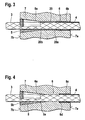
- Fig. 4 shows a second embodiment of such a device for Prevent axial movement of the PE jacket 4.
- a blind hole-like extension 6c which is an annular shoulder at the transition to the cylindrical region 6b 6d forms. If the diameter of the cylindrical portion 6b is only so large, that the strand 3 can just pass through, the strand 3 finds in its rest Area closely fitting surrounding PE jacket 4 on this shoulder 6d Stop, which also prevents him from longitudinal displacement when the wire 3 stretching during tensioning and consequent longitudinal movement through the Armature disc 7 experiences.
- Figs. 5 and 6 in similar representations as shown in FIGS. 2 and 3.
- Fig. 5 shows the state during tensioning
- Fig. 6 the tense and anchored condition.
- the attachment head 21 a - not shown - Clamping press, which is supported on the top 7b of the armature disk 7 Stamp 22 arranged with a lower flange 23 opposite air-side thicker end 5b of the wedge 5 is supported.
- the has in the side wall Attachment head 21 has a recess 24 in which a clamping screw 25 can be moved is that can be screwed into a transverse bore in the punch 22.
- the longitudinal movement of the ring wedge 5 when tensioning the strand 3 in Direction of arrow 26 is limited by the fact that the thicker end 5b of the air side Ring wedge 5 finds a stop on the flange 23 of the punch 22, which in turn rests on a shoulder 27 inside the attachment head 21. Thereby the wedge 5 is prevented from opening too wide.
Landscapes
- Engineering & Computer Science (AREA)
- Architecture (AREA)
- Civil Engineering (AREA)
- Structural Engineering (AREA)
- Mechanical Engineering (AREA)
- Bridges Or Land Bridges (AREA)
- Piles And Underground Anchors (AREA)
- Reinforcement Elements For Buildings (AREA)
- Coating With Molten Metal (AREA)
- Ropes Or Cables (AREA)
Description
- Fig. 1
- einen Längsschnitt durch eine Verankerungsvorrichtung gemäß der Erfindung,
- Fig. 2
- einen Querschnitt entlang der Linie II-II in Fig. 1,
- Fig. 3
- als Detail in größerem Maßstab den Verankerungsbereich einer Litze in verankertem Zustand,
- Fig. 4
- in einer entsprechenden Darstellung eine weitere Ausführungsform und die
- Fig. 5 und 6
- in entsprechenden Darstellungen den Spann- bzw. Verankerungsvorgang.
Claims (10)
- Verfahren zum Einbauen und Spannen eines freigespannten Zugglieds, zum Beispiel eines Schrägseils für eine Schrägseilbrücke, eines externen Spannglieds oder dergleichen aus einem Bündel von kunststoffummantelten Einzelelementen aus Stahl, wie zum Beispiel Drähten, Litzen oder dergleichen, die an den Enden jeweils mittels Keilen in einer gegenüber dem Bauwerk abgestützten Ankerscheibe verankert werden, wobei die Einzelelemente im Bereich der Verankerung freigelegt werden, dadurch gekennzeichnet, dass der Kunststoff-Mantel (4) der Einzelelemente (2) während der beim Spannen erfolgenden Dehnung jedes einzelnen Elementes (2) durch Anschlag an einer das Element (2) im Verankerungsbereich ringförmig umgebenden Schulter (20a, 6d) an einer Längsbewegung gehindert und dadurch gestaucht wird.
- Verfahren nach Anspruch 1, dadurch gekennzeichnet, dass Vorkehrungen getroffen werden, um den Keil (5) nach dem Spannen gegen die Rückstellkraft des gestauchten Kunststoff-Mantels (4) in die Verankerungsposition in der Ankerscheibe (7) zu bringen.
- Verfahren nach Anspruch 2, dadurch gekennzeichnet, dass der Keil (5) unter Festhaltung des gespannten Einzelelementes (2) durch eine äußere Längskraft in seinen Sitz in der Bohrung (6) in der Ankerscheibe (7) gedrückt wird.
- Verfahren nach Anspruch 2, dadurch gekennzeichnet, dass das Einzelelement (2) um einen gewissen Betrag überspannt wird, dass der Keil (5) an dem überspannten Einzelelement (2) fixiert und beim Nachlassen der Spannkraft auf den vorbestimmten Wert durch dieses in seinen Sitz in der Bohrung (6) in der Ankerscheibe (7) gezogen wird.
- Verfahren nach einem der Ansprüche 1 bis 4, dadurch gekennzeichnet, dass beim Spannen der Einzelelemente (2) die durch Mitnahme eintretende Längsbewegung des Keils (5) durch einen Anschlag begrenzt wird.
- Verfahren nach Anspruch 1, dadurch gekennzeichnet, dass die Einzelelemente (2) bei längeren Spannwegen in aufeinanderfolgenden Stufen freigelegt werden, nämlich in einer ersten Stufe durch Abschälen und Entfernen des Kunststoff-Mantels (4) und in einer zweiten Stufe durch Zurückhalten und Stauchen des Kunststoff-Mantels (4).
- Verankerungsvorrichtung zum Einbauen und Spannen eines freigespannten Zugglieds (1) mit kunststoffummantelten Einzelelementen (2) und zum Durchführen des Verfahrens nach Anspruch 1 mit einer gegenüber dem Bauwerk abstützbaren Ankerscheibe mit einer Anzahl von Bohrungen (6) für den Durchtritt der Einzelelemente (2) zur Verankerung mittels Keilen (5), dadurch gekennzeichnet, dass die den Anschlag für die Rückhaltung des Kunststoff-Mantels (4) bildende Schulter an einer Stirnseite (20a) eines jeweils ein Einzelelement (2) im Bereich der Bohrungen (6) umgebenden Druckrohres (20) gebildet ist, das mit seiner gegenüberliegenden Stirnseite (20b) an dem Verankerungskeil (5) anliegt.
- Verankerungsvonichtung mit einem Druckrohr (20) nach Anspruch 7, dadurch gekennzeichnet, dass der Innendurchmesser des Druckrohres (20) dem Außendurchmesser des jeweiligen Einzelelements (2) und sein Außendurchmesser dem Innendurchmesser der Bohrung (6) in der Ankerscheibe (7) entsprechen.
- Verankerungsvorrichtung zum Einbauen und Spannen eines freigespannten Zugglieds (1) mit kunststoffummantelten Einzelelementen (2) und zum Durchführen des Verfahrens nach Anspruch 1 mit einer gegenüber dem Bauwerk abstützbaren Ankerscheibe mit einer Anzahl von Bohrungen für den Durchtritt der Einzelelemente zur Verankerung mittels Keilen, dadurch gekennzeichnet, dass die den Anschlag für die Rückhaltung des Kunststoff-Mantels (4) bildende Schulter (6d) am Grunde einer sacklochartigen Erweiterung (6c) der Bohrungen (6) für die Einzelelemente (2) in der Ankerscheibe (7) gebildet ist.
- Verankerungsvorrichtung zum Einbauen und Spannen eines freigespannten Zugglieds (1) mit kunststoffummantelten Einzelelementen (2) und zum Durchführen des Verfahrens nach Anspruch 1 mit einer gegenüber dem Bauwerk abstützbaren Ankerscheibe mit einer Anzahl von Bohrungen für den Durchtritt der Einzelelemente zur Verankerung mittels Keilen, dadurch gekennzeichnet, dass die den Anschlag für die Rückhaltung des Kunststoff-Mantels (4) bildende Schulter an einem der Ankerscheibe (7) bauwerksseitig nachgeordneten Abstandhalter (14) angeordnet ist, der mit Bohrungen für den Durchtritt der Einzelelemente (2) versehen ist.
Applications Claiming Priority (2)
| Application Number | Priority Date | Filing Date | Title |
|---|---|---|---|
| DE10062227 | 2000-12-13 | ||
| DE10062227A DE10062227A1 (de) | 2000-12-13 | 2000-12-13 | Verfahren zum Einbauen und Spannen eines freigespannten Zugglieds, insbesondere eines Schrägseils für eine Schrägseilbrücke sowie Verankerungsvorrichtung zum Durchführen des Verfahrens |
Publications (3)
| Publication Number | Publication Date |
|---|---|
| EP1215347A2 EP1215347A2 (de) | 2002-06-19 |
| EP1215347A3 EP1215347A3 (de) | 2002-10-30 |
| EP1215347B1 true EP1215347B1 (de) | 2004-03-03 |
Family
ID=7667064
Family Applications (1)
| Application Number | Title | Priority Date | Filing Date |
|---|---|---|---|
| EP01128712A Expired - Lifetime EP1215347B1 (de) | 2000-12-13 | 2001-12-03 | Verfahren zum Einbauen und Spannen eines freigespannten Zugglieds, sowie Verankerungsvorrichtung zum Durchführen des Verfahrens |
Country Status (7)
| Country | Link |
|---|---|
| US (1) | US6634147B2 (de) |
| EP (1) | EP1215347B1 (de) |
| JP (1) | JP3831241B2 (de) |
| KR (1) | KR100641403B1 (de) |
| AT (1) | ATE261034T1 (de) |
| DE (2) | DE10062227A1 (de) |
| TW (1) | TW508396B (de) |
Families Citing this family (25)
| Publication number | Priority date | Publication date | Assignee | Title |
|---|---|---|---|---|
| DE20205149U1 (de) * | 2002-04-03 | 2002-07-04 | DYWIDAG-Systems International GmbH, 85609 Aschheim | Korrosionsgeschütztes Zugglied, insbesondere Schrägseil für eine Schrägseilbrücke |
| EP1514981A1 (de) * | 2002-05-30 | 2005-03-16 | Anderson Technology Corporation | Spannungsendteilkonstruktion von spannbetonkonstruktionskörper und verfahren zur herstellung des spannungsendteils |
| DE20311950U1 (de) * | 2003-08-02 | 2004-12-09 | Dywidag-Systems International Gmbh | Korrosionsgeschütztes Zugglied, insbesondere Spannglied für Spannbeton |
| EP1668202A1 (de) * | 2003-10-03 | 2006-06-14 | University Of Waterloo | Zugankersystem |
| EP1757819A4 (de) * | 2004-04-07 | 2011-03-30 | Sumitomo Sei Steel Wire Corp | Gleichmässig anordnendes werkzeug für einen spreizanker |
| KR101255568B1 (ko) * | 2006-04-20 | 2013-04-17 | 파우에스엘 인터나치오날 아게 | 가닥 안내 장치 및 가닥 안내 장치를 포함하는 구조체 |
| ES2317743B1 (es) * | 2006-06-30 | 2010-02-05 | Tecnicas Del Pretensado Y Servicios Auxiliares, S.L. | Sistema de estanqueidad para anclajes en puentes atirantados. |
| US20090178352A1 (en) * | 2008-01-15 | 2009-07-16 | Innovate International, Limited | Composite Structural Member |
| US8904721B2 (en) * | 2008-06-12 | 2014-12-09 | University Of Utah Research Foundation | Anchoring, splicing and tensioning elongated reinforcement members |
| CN102159768A (zh) * | 2008-06-12 | 2011-08-17 | 犹他大学研究基金会 | 细长加强构件的锚固、拼接和张紧 |
| KR100912768B1 (ko) | 2009-04-28 | 2009-08-18 | 주식회사 삼우기초기술 | 와이어 인장기 |
| CA2793733A1 (en) | 2010-04-13 | 2011-10-20 | The University Of Utah Research Foundation | Sheet and rod attachment apparatus and system |
| FR2973818B1 (fr) * | 2011-04-07 | 2017-06-02 | Soletanche Freyssinet | Procede et dispositif de protection de l'extremite d'un cable ancre |
| HUE027404T2 (en) * | 2011-04-15 | 2016-10-28 | Soletanche Freyssinet | Fastening assembly |
| EP2703331B1 (de) * | 2012-09-03 | 2014-12-24 | Soletanche Freyssinet | Traktionssystem unter Verwendung eines mehrsehnigen Kabels mit einem Ablenkungswinkel |
| DE102013215136A1 (de) * | 2013-08-01 | 2015-02-05 | Dywidag-Systems International Gmbh | Korrosionsgeschütztes Zugglied und plastisch verformbare Scheibe aus Korrosionsschutzmaterial für ein derartiges Zugglied |
| CN104452595B (zh) * | 2014-11-12 | 2016-05-25 | 河海大学 | 单、双耳套筒单、双向调节斜拉索的张拉装置的施工方法 |
| CN106869027B (zh) * | 2017-03-05 | 2018-05-29 | 郑州大学 | 一种实现平行钢丝斜拉索破断预警的方法 |
| EP3740348A4 (de) * | 2018-01-19 | 2022-01-26 | E-Longation, LLC | Verfahren und vorrichtung zur durchführung von felddehnungsmessungen |
| US10830655B2 (en) | 2018-01-19 | 2020-11-10 | E-Longation, Llc | Method and apparatus for performing field elongation measurements |
| CN109944158A (zh) * | 2019-03-26 | 2019-06-28 | 江阴法尔胜住电新材料有限公司 | 一种斜拉索梁端密封结构 |
| JP7348450B2 (ja) * | 2019-09-30 | 2023-09-21 | 住友電気工業株式会社 | 緊張材の定着構造 |
| CN111550555B (zh) * | 2020-05-18 | 2022-04-08 | 海盐建浩金属股份有限公司 | 一种锚具防护罩 |
| CN112176881A (zh) * | 2020-10-16 | 2021-01-05 | 盐城市双强管桩有限公司 | 一种斜拉索整束智能张拉设备 |
| US12054947B1 (en) * | 2024-01-08 | 2024-08-06 | King Faisal University | Multi-layer wedge anchorage for FRP plates and FRP tendons |
Family Cites Families (25)
| Publication number | Priority date | Publication date | Assignee | Title |
|---|---|---|---|---|
| US3844697A (en) * | 1968-08-27 | 1974-10-29 | H Edwards | Tendon anchorage assembly with threaded support member for concrete formwork |
| US4205926A (en) * | 1977-08-15 | 1980-06-03 | Carlson Drexel T | Sucker rod and coupling therefor |
| DE8002045U1 (de) * | 1980-01-26 | 1980-04-30 | Dyckerhoff & Widmann Ag, 8000 Muenchen | Wiedergewinnbares schalungsteil fuer den verankerungsbereich eines spannglieds in einem betonbauteil |
| DE8002044U1 (de) * | 1980-01-26 | 1980-04-30 | Dyckerhoff & Widmann Ag, 8000 Muenchen | Keilverankerung fuer ein spannglied in einem betonbauteil |
| JPS60154405U (ja) * | 1984-03-26 | 1985-10-15 | 株式会社 春本鉄工所 | 橋梁ケ−ブルの外装材 |
| US4616458A (en) * | 1985-07-01 | 1986-10-14 | Vsl Corporation | Protective apparatus for tendons in tendon tensioning anchor assemblies |
| US4773198A (en) * | 1986-09-05 | 1988-09-27 | Continental Concrete Structures, Inc. | Post-tensioning anchorages for aggressive environments |
| DE3734953C2 (de) * | 1987-03-13 | 1994-02-24 | Dyckerhoff & Widmann Ag | Abstandhalter für ein spannbares Zugglied |
| CH676617A5 (de) * | 1987-03-13 | 1991-02-15 | Dyckerhoff & Widmann Ag | |
| US4837885A (en) * | 1988-08-01 | 1989-06-13 | T.Y. Lin International | Prestressed stay cable for use in cable-stayed bridges |
| US5289626A (en) * | 1989-03-27 | 1994-03-01 | Kajima Corporation | Foundation anchor and method for securing same to a foundation |
| GB8924896D0 (en) * | 1989-11-03 | 1989-12-20 | Manuf Aceros Caucho Sa | Anchorage for stressed reinforcing tendon |
| JPH055365A (ja) * | 1991-06-05 | 1993-01-14 | Nippon Concrete Ind Co Ltd | プレストレストコンクリート部材のfrp緊張材定着方法 |
| JPH0713401B2 (ja) * | 1991-08-07 | 1995-02-15 | 黒沢建設株式会社 | 緊張ジャッキの方向位置決め装置及びその方向位置決め方法 |
| DE4138470A1 (de) * | 1991-11-22 | 1993-05-27 | Bauer Spezialtiefbau | Vorrichtung zum spannen und verkeilen von zugelementen |
| DE29504739U1 (de) * | 1995-03-20 | 1995-05-18 | Dyckerhoff & Widmann AG, 81902 München | Korrosionsgeschütztes Zugglied, vornehmlich externes Spannglied für Spannbeton ohne Verbund |
| US5701707A (en) * | 1996-05-06 | 1997-12-30 | Sorkin; Felix L. | Bonded slab post-tension system |
| DE19634682C2 (de) * | 1996-08-28 | 1999-07-08 | Dyckerhoff & Widmann Ag | Dichtung zur Begrenzung von mit einer Vergußmasse auszufüllenden Bereichen an einem Bündelzugglied für Spannbeton |
| JP3148807B2 (ja) * | 1997-05-07 | 2001-03-26 | 建設基礎エンジニアリング株式会社 | グラウンドアンカーの定着頭部 |
| DE19733822A1 (de) * | 1997-08-05 | 1999-02-11 | Dyckerhoff & Widmann Ag | Verfahren zum Einbauen und Spannen eines freigespannten Zugglieds und Vorrichtung zum Durchführen des Verfahrens |
| FR2773186B1 (fr) * | 1997-12-31 | 2002-06-28 | Jae Man Park | Appareil de remise sous tension d'une structure precontrainte |
| DE19814419A1 (de) * | 1998-03-31 | 1999-10-07 | Suspa Spannbeton Gmbh | Vorrichtung zum Abtrennen und Entfernen eines Abschnitts eines Kunststoffrohres von einem von diesem umgebenen Spannstahl |
| EP1020146A4 (de) * | 1998-07-31 | 2006-02-22 | France Bed Company Ltd | Matratze und bett |
| CN1220836C (zh) * | 1999-04-14 | 2005-09-28 | 阿伦·F·罗德里古兹 | 密封结构、密封方法和后张紧锚接密封盖 |
| US6381912B1 (en) * | 2000-12-29 | 2002-05-07 | Felix L. Sorkin | Apparatus and method for sealing an intermediate anchor of a post-tension anchor system |
-
2000
- 2000-12-13 DE DE10062227A patent/DE10062227A1/de not_active Withdrawn
-
2001
- 2001-12-03 AT AT01128712T patent/ATE261034T1/de not_active IP Right Cessation
- 2001-12-03 DE DE50101596T patent/DE50101596D1/de not_active Expired - Lifetime
- 2001-12-03 EP EP01128712A patent/EP1215347B1/de not_active Expired - Lifetime
- 2001-12-07 TW TW090130344A patent/TW508396B/zh not_active IP Right Cessation
- 2001-12-12 KR KR1020010078447A patent/KR100641403B1/ko not_active Expired - Fee Related
- 2001-12-12 JP JP2001378930A patent/JP3831241B2/ja not_active Expired - Fee Related
- 2001-12-12 US US10/016,649 patent/US6634147B2/en not_active Expired - Lifetime
Also Published As
| Publication number | Publication date |
|---|---|
| JP2002235303A (ja) | 2002-08-23 |
| KR20020046973A (ko) | 2002-06-21 |
| DE10062227A1 (de) | 2002-06-20 |
| KR100641403B1 (ko) | 2006-10-31 |
| TW508396B (en) | 2002-11-01 |
| US20020088105A1 (en) | 2002-07-11 |
| US6634147B2 (en) | 2003-10-21 |
| EP1215347A2 (de) | 2002-06-19 |
| EP1215347A3 (de) | 2002-10-30 |
| JP3831241B2 (ja) | 2006-10-11 |
| DE50101596D1 (de) | 2004-04-08 |
| ATE261034T1 (de) | 2004-03-15 |
Similar Documents
| Publication | Publication Date | Title |
|---|---|---|
| EP1215347A2 (de) | Verfahren zum Einbauen und Spannen eines freigespannten Zugglieds, sowie Verankerungsvorrichtung zum Durchführen des Verfahrens | |
| EP0196451B1 (de) | Zugglied für einen Felsbolzen oder dergleichen | |
| EP0364802B1 (de) | Verankerungsvorrichtung für das stabförmige Zugglied eines Ankers, insbesondere eines Felsankers | |
| EP1490554B1 (de) | Verankerungsvorrichtung für ein korrosionsgeschütztes zugglied, insbesondere schrägseil für eine schrägseilbrücke | |
| DE3734954C2 (de) | ||
| EP1505223B1 (de) | Korrosionsgeschütztes Zugglied, insbesondere Spannglied für Spannbeton | |
| DE3734953C2 (de) | Abstandhalter für ein spannbares Zugglied | |
| CH676617A5 (de) | ||
| EP3027821B1 (de) | Korrosionsgeschütztes zugglied und plastisch verformbare scheibe aus korrosionsschutzmaterial für ein derartiges zugglied | |
| CH662604A5 (de) | Verankerungsvorrichtung und kopplungsvorrichtung fuer buendelspannglieder fuer spannbeton. | |
| DE19731448C2 (de) | Befestigungsvorrichtung für Rundkabel in Wandungen | |
| EP0703326A1 (de) | Korrosionsgeschütztes Zugglied, vornehmlich Spannglied für Spannbeton ohne Verbund | |
| DE1400234A1 (de) | Verfahren zum Verschrauben von Konstruktionsteilen und Mittel zu seiner Durchfuehrung | |
| DE3801451C2 (de) | Korrosionsgeschütztes freies Zugglied, vornehmlich Spannglied für Spannbeton ohne Verbund | |
| DE29506476U1 (de) | Vorrichtung zur Verwendung beim Einführen der einzelnen Zugelemente eines frei gespannten Zugglieds | |
| DE3320460C1 (de) | Nachgiebiger Gebirgsanker | |
| DE1925171A1 (de) | Verbindungsvorrichtung oder Kupplung | |
| DE19828141C2 (de) | Rohrverbindung, insbesondere für Kunststoffrohre bzw. Verbundrohre | |
| EP3555369A2 (de) | Verfahren zum installieren eines spannelements in einem ankerblock halterung, insbesondere zur durchführung des verfahrens und kombination einer halterung mit einem spannelement | |
| EP0330114A1 (de) | In ein vorgebohrtes Loch einer mehrschaligen Gebaüdewand einzusetzender Injektionsanker | |
| DE3834731C2 (de) | ||
| EP0913538A2 (de) | Vorrichtung zur Vorspannung von Bauwerken ohne Verbund | |
| DE3873486T2 (de) | Verfahren und mittel zur verbindung von bauteilen. | |
| DE3938910C1 (en) | Plastic wall grommet-like arrangement for cabling - has outer threaded tube in bored hole fitted with flange section widened to funnel shape | |
| EP1112422A2 (de) | Vorrichtung zur externen vorspannung von bauwerken |
Legal Events
| Date | Code | Title | Description |
|---|---|---|---|
| PUAI | Public reference made under article 153(3) epc to a published international application that has entered the european phase |
Free format text: ORIGINAL CODE: 0009012 |
|
| AK | Designated contracting states |
Kind code of ref document: A2 Designated state(s): AT BE CH CY DE DK ES FI FR GB GR IE IT LI LU MC NL PT SE TR |
|
| AX | Request for extension of the european patent |
Free format text: AL;LT;LV;MK;RO;SI |
|
| PUAL | Search report despatched |
Free format text: ORIGINAL CODE: 0009013 |
|
| AK | Designated contracting states |
Kind code of ref document: A3 Designated state(s): AT BE CH CY DE DK ES FI FR GB GR IE IT LI LU MC NL PT SE TR |
|
| AX | Request for extension of the european patent |
Free format text: AL;LT;LV;MK;RO;SI |
|
| 17P | Request for examination filed |
Effective date: 20021126 |
|
| 17Q | First examination report despatched |
Effective date: 20030116 |
|
| RAP1 | Party data changed (applicant data changed or rights of an application transferred) |
Owner name: DYWIDAG-SYSTEMS INTERNATIONAL GMBH |
|
| AKX | Designation fees paid |
Designated state(s): AT BE CH CY DE DK ES FI FR GB GR IE IT LI LU MC NL PT SE TR |
|
| GRAP | Despatch of communication of intention to grant a patent |
Free format text: ORIGINAL CODE: EPIDOSNIGR1 |
|
| GRAS | Grant fee paid |
Free format text: ORIGINAL CODE: EPIDOSNIGR3 |
|
| GRAA | (expected) grant |
Free format text: ORIGINAL CODE: 0009210 |
|
| AK | Designated contracting states |
Kind code of ref document: B1 Designated state(s): AT BE CH CY DE DK ES FI FR GB GR IE IT LI LU MC NL PT SE TR |
|
| PG25 | Lapsed in a contracting state [announced via postgrant information from national office to epo] |
Ref country code: IT Free format text: LAPSE BECAUSE OF FAILURE TO SUBMIT A TRANSLATION OF THE DESCRIPTION OR TO PAY THE FEE WITHIN THE PRESCRIBED TIME-LIMIT;WARNING: LAPSES OF ITALIAN PATENTS WITH EFFECTIVE DATE BEFORE 2007 MAY HAVE OCCURRED AT ANY TIME BEFORE 2007. THE CORRECT EFFECTIVE DATE MAY BE DIFFERENT FROM THE ONE RECORDED. Effective date: 20040303 Ref country code: GB Free format text: LAPSE BECAUSE OF FAILURE TO SUBMIT A TRANSLATION OF THE DESCRIPTION OR TO PAY THE FEE WITHIN THE PRESCRIBED TIME-LIMIT Effective date: 20040303 Ref country code: IE Free format text: LAPSE BECAUSE OF FAILURE TO SUBMIT A TRANSLATION OF THE DESCRIPTION OR TO PAY THE FEE WITHIN THE PRESCRIBED TIME-LIMIT Effective date: 20040303 Ref country code: TR Free format text: LAPSE BECAUSE OF FAILURE TO SUBMIT A TRANSLATION OF THE DESCRIPTION OR TO PAY THE FEE WITHIN THE PRESCRIBED TIME-LIMIT Effective date: 20040303 Ref country code: FI Free format text: LAPSE BECAUSE OF FAILURE TO SUBMIT A TRANSLATION OF THE DESCRIPTION OR TO PAY THE FEE WITHIN THE PRESCRIBED TIME-LIMIT Effective date: 20040303 Ref country code: CY Free format text: LAPSE BECAUSE OF FAILURE TO SUBMIT A TRANSLATION OF THE DESCRIPTION OR TO PAY THE FEE WITHIN THE PRESCRIBED TIME-LIMIT Effective date: 20040303 |
|
| REG | Reference to a national code |
Ref country code: GB Ref legal event code: FG4D Free format text: NOT ENGLISH |
|
| REG | Reference to a national code |
Ref country code: CH Ref legal event code: EP |
|
| REG | Reference to a national code |
Ref country code: IE Ref legal event code: FG4D Free format text: GERMAN |
|
| REF | Corresponds to: |
Ref document number: 50101596 Country of ref document: DE Date of ref document: 20040408 Kind code of ref document: P |
|
| PG25 | Lapsed in a contracting state [announced via postgrant information from national office to epo] |
Ref country code: DK Free format text: LAPSE BECAUSE OF FAILURE TO SUBMIT A TRANSLATION OF THE DESCRIPTION OR TO PAY THE FEE WITHIN THE PRESCRIBED TIME-LIMIT Effective date: 20040603 Ref country code: GR Free format text: LAPSE BECAUSE OF FAILURE TO SUBMIT A TRANSLATION OF THE DESCRIPTION OR TO PAY THE FEE WITHIN THE PRESCRIBED TIME-LIMIT Effective date: 20040603 Ref country code: SE Free format text: LAPSE BECAUSE OF FAILURE TO SUBMIT A TRANSLATION OF THE DESCRIPTION OR TO PAY THE FEE WITHIN THE PRESCRIBED TIME-LIMIT Effective date: 20040603 |
|
| PG25 | Lapsed in a contracting state [announced via postgrant information from national office to epo] |
Ref country code: ES Free format text: LAPSE BECAUSE OF FAILURE TO SUBMIT A TRANSLATION OF THE DESCRIPTION OR TO PAY THE FEE WITHIN THE PRESCRIBED TIME-LIMIT Effective date: 20040614 |
|
| GBV | Gb: ep patent (uk) treated as always having been void in accordance with gb section 77(7)/1977 [no translation filed] |
Effective date: 20040303 |
|
| REG | Reference to a national code |
Ref country code: IE Ref legal event code: FD4D |
|
| ET | Fr: translation filed | ||
| PG25 | Lapsed in a contracting state [announced via postgrant information from national office to epo] |
Ref country code: LU Free format text: LAPSE BECAUSE OF NON-PAYMENT OF DUE FEES Effective date: 20041203 Ref country code: AT Free format text: LAPSE BECAUSE OF NON-PAYMENT OF DUE FEES Effective date: 20041203 |
|
| PG25 | Lapsed in a contracting state [announced via postgrant information from national office to epo] |
Ref country code: MC Free format text: LAPSE BECAUSE OF NON-PAYMENT OF DUE FEES Effective date: 20041231 |
|
| PLBE | No opposition filed within time limit |
Free format text: ORIGINAL CODE: 0009261 |
|
| STAA | Information on the status of an ep patent application or granted ep patent |
Free format text: STATUS: NO OPPOSITION FILED WITHIN TIME LIMIT |
|
| 26N | No opposition filed |
Effective date: 20041206 |
|
| PG25 | Lapsed in a contracting state [announced via postgrant information from national office to epo] |
Ref country code: LI Free format text: LAPSE BECAUSE OF NON-PAYMENT OF DUE FEES Effective date: 20051231 Ref country code: CH Free format text: LAPSE BECAUSE OF NON-PAYMENT OF DUE FEES Effective date: 20051231 |
|
| REG | Reference to a national code |
Ref country code: CH Ref legal event code: PL |
|
| PG25 | Lapsed in a contracting state [announced via postgrant information from national office to epo] |
Ref country code: PT Free format text: LAPSE BECAUSE OF NON-PAYMENT OF DUE FEES Effective date: 20040803 |
|
| PGFP | Annual fee paid to national office [announced via postgrant information from national office to epo] |
Ref country code: DE Payment date: 20131230 Year of fee payment: 13 |
|
| PGFP | Annual fee paid to national office [announced via postgrant information from national office to epo] |
Ref country code: NL Payment date: 20141226 Year of fee payment: 14 |
|
| PGFP | Annual fee paid to national office [announced via postgrant information from national office to epo] |
Ref country code: BE Payment date: 20141229 Year of fee payment: 14 |
|
| REG | Reference to a national code |
Ref country code: DE Ref legal event code: R119 Ref document number: 50101596 Country of ref document: DE |
|
| PG25 | Lapsed in a contracting state [announced via postgrant information from national office to epo] |
Ref country code: DE Free format text: LAPSE BECAUSE OF NON-PAYMENT OF DUE FEES Effective date: 20150701 |
|
| REG | Reference to a national code |
Ref country code: FR Ref legal event code: PLFP Year of fee payment: 15 |
|
| PG25 | Lapsed in a contracting state [announced via postgrant information from national office to epo] |
Ref country code: BE Free format text: LAPSE BECAUSE OF NON-PAYMENT OF DUE FEES Effective date: 20151231 |
|
| REG | Reference to a national code |
Ref country code: NL Ref legal event code: MM Effective date: 20160101 |
|
| PG25 | Lapsed in a contracting state [announced via postgrant information from national office to epo] |
Ref country code: NL Free format text: LAPSE BECAUSE OF NON-PAYMENT OF DUE FEES Effective date: 20160101 |
|
| REG | Reference to a national code |
Ref country code: FR Ref legal event code: PLFP Year of fee payment: 16 |
|
| REG | Reference to a national code |
Ref country code: FR Ref legal event code: PLFP Year of fee payment: 17 |
|
| PGFP | Annual fee paid to national office [announced via postgrant information from national office to epo] |
Ref country code: FR Payment date: 20181226 Year of fee payment: 18 |
|
| PG25 | Lapsed in a contracting state [announced via postgrant information from national office to epo] |
Ref country code: FR Free format text: LAPSE BECAUSE OF NON-PAYMENT OF DUE FEES Effective date: 20191231 |