EP1213397A1 - Corps structural accouple - Google Patents
Corps structural accouple Download PDFInfo
- Publication number
- EP1213397A1 EP1213397A1 EP00955048A EP00955048A EP1213397A1 EP 1213397 A1 EP1213397 A1 EP 1213397A1 EP 00955048 A EP00955048 A EP 00955048A EP 00955048 A EP00955048 A EP 00955048A EP 1213397 A1 EP1213397 A1 EP 1213397A1
- Authority
- EP
- European Patent Office
- Prior art keywords
- structural member
- joining structure
- tabular
- stress
- reinforcing rib
- Prior art date
- Legal status (The legal status is an assumption and is not a legal conclusion. Google has not performed a legal analysis and makes no representation as to the accuracy of the status listed.)
- Granted
Links
- 230000003014 reinforcing effect Effects 0.000 claims abstract description 71
- 238000005304 joining Methods 0.000 claims abstract description 61
- 238000010168 coupling process Methods 0.000 claims description 13
- 230000008878 coupling Effects 0.000 claims description 12
- 238000005859 coupling reaction Methods 0.000 claims description 12
- 238000005452 bending Methods 0.000 claims description 11
- 238000003466 welding Methods 0.000 abstract description 22
- 230000007423 decrease Effects 0.000 abstract description 3
- 229910000831 Steel Inorganic materials 0.000 description 22
- 239000010959 steel Substances 0.000 description 22
- 230000000694 effects Effects 0.000 description 7
- 210000003371 toe Anatomy 0.000 description 6
- 238000005516 engineering process Methods 0.000 description 4
- 238000004458 analytical method Methods 0.000 description 2
- 238000004873 anchoring Methods 0.000 description 2
- 239000012141 concentrate Substances 0.000 description 2
- 238000010276 construction Methods 0.000 description 2
- 239000000463 material Substances 0.000 description 2
- 238000005259 measurement Methods 0.000 description 2
- 238000000034 method Methods 0.000 description 2
- 241000237509 Patinopecten sp. Species 0.000 description 1
- 230000002411 adverse Effects 0.000 description 1
- 230000015572 biosynthetic process Effects 0.000 description 1
- 230000002301 combined effect Effects 0.000 description 1
- 238000005520 cutting process Methods 0.000 description 1
- 238000009826 distribution Methods 0.000 description 1
- 238000005755 formation reaction Methods 0.000 description 1
- 238000005286 illumination Methods 0.000 description 1
- 238000005297 material degradation process Methods 0.000 description 1
- 235000020637 scallop Nutrition 0.000 description 1
- 230000007847 structural defect Effects 0.000 description 1
Images


Classifications
-
- E—FIXED CONSTRUCTIONS
- E04—BUILDING
- E04B—GENERAL BUILDING CONSTRUCTIONS; WALLS, e.g. PARTITIONS; ROOFS; FLOORS; CEILINGS; INSULATION OR OTHER PROTECTION OF BUILDINGS
- E04B1/00—Constructions in general; Structures which are not restricted either to walls, e.g. partitions, or floors or ceilings or roofs
- E04B1/18—Structures comprising elongated load-supporting parts, e.g. columns, girders, skeletons
- E04B1/24—Structures comprising elongated load-supporting parts, e.g. columns, girders, skeletons the supporting parts consisting of metal
- E04B1/2403—Connection details of the elongated load-supporting parts
-
- E—FIXED CONSTRUCTIONS
- E04—BUILDING
- E04H—BUILDINGS OR LIKE STRUCTURES FOR PARTICULAR PURPOSES; SWIMMING OR SPLASH BATHS OR POOLS; MASTS; FENCING; TENTS OR CANOPIES, IN GENERAL
- E04H12/00—Towers; Masts or poles; Chimney stacks; Water-towers; Methods of erecting such structures
- E04H12/22—Sockets or holders for poles or posts
- E04H12/2253—Mounting poles or posts to the holder
- E04H12/2261—Mounting poles or posts to the holder on a flat base
-
- E—FIXED CONSTRUCTIONS
- E04—BUILDING
- E04B—GENERAL BUILDING CONSTRUCTIONS; WALLS, e.g. PARTITIONS; ROOFS; FLOORS; CEILINGS; INSULATION OR OTHER PROTECTION OF BUILDINGS
- E04B1/00—Constructions in general; Structures which are not restricted either to walls, e.g. partitions, or floors or ceilings or roofs
- E04B1/18—Structures comprising elongated load-supporting parts, e.g. columns, girders, skeletons
- E04B1/24—Structures comprising elongated load-supporting parts, e.g. columns, girders, skeletons the supporting parts consisting of metal
- E04B1/2403—Connection details of the elongated load-supporting parts
- E04B2001/2415—Brackets, gussets, joining plates
-
- E—FIXED CONSTRUCTIONS
- E04—BUILDING
- E04B—GENERAL BUILDING CONSTRUCTIONS; WALLS, e.g. PARTITIONS; ROOFS; FLOORS; CEILINGS; INSULATION OR OTHER PROTECTION OF BUILDINGS
- E04B1/00—Constructions in general; Structures which are not restricted either to walls, e.g. partitions, or floors or ceilings or roofs
- E04B1/18—Structures comprising elongated load-supporting parts, e.g. columns, girders, skeletons
- E04B1/24—Structures comprising elongated load-supporting parts, e.g. columns, girders, skeletons the supporting parts consisting of metal
- E04B1/2403—Connection details of the elongated load-supporting parts
- E04B2001/2445—Load-supporting elements with reinforcement at the connection point other than the connector
-
- E—FIXED CONSTRUCTIONS
- E04—BUILDING
- E04B—GENERAL BUILDING CONSTRUCTIONS; WALLS, e.g. PARTITIONS; ROOFS; FLOORS; CEILINGS; INSULATION OR OTHER PROTECTION OF BUILDINGS
- E04B1/00—Constructions in general; Structures which are not restricted either to walls, e.g. partitions, or floors or ceilings or roofs
- E04B1/18—Structures comprising elongated load-supporting parts, e.g. columns, girders, skeletons
- E04B1/24—Structures comprising elongated load-supporting parts, e.g. columns, girders, skeletons the supporting parts consisting of metal
- E04B1/2403—Connection details of the elongated load-supporting parts
- E04B2001/2448—Connections between open section profiles
-
- E—FIXED CONSTRUCTIONS
- E04—BUILDING
- E04B—GENERAL BUILDING CONSTRUCTIONS; WALLS, e.g. PARTITIONS; ROOFS; FLOORS; CEILINGS; INSULATION OR OTHER PROTECTION OF BUILDINGS
- E04B1/00—Constructions in general; Structures which are not restricted either to walls, e.g. partitions, or floors or ceilings or roofs
- E04B1/18—Structures comprising elongated load-supporting parts, e.g. columns, girders, skeletons
- E04B1/24—Structures comprising elongated load-supporting parts, e.g. columns, girders, skeletons the supporting parts consisting of metal
- E04B1/2403—Connection details of the elongated load-supporting parts
- E04B2001/2451—Connections between closed section profiles
-
- E—FIXED CONSTRUCTIONS
- E04—BUILDING
- E04B—GENERAL BUILDING CONSTRUCTIONS; WALLS, e.g. PARTITIONS; ROOFS; FLOORS; CEILINGS; INSULATION OR OTHER PROTECTION OF BUILDINGS
- E04B1/00—Constructions in general; Structures which are not restricted either to walls, e.g. partitions, or floors or ceilings or roofs
- E04B1/18—Structures comprising elongated load-supporting parts, e.g. columns, girders, skeletons
- E04B1/24—Structures comprising elongated load-supporting parts, e.g. columns, girders, skeletons the supporting parts consisting of metal
- E04B1/2403—Connection details of the elongated load-supporting parts
- E04B2001/2457—Beam to beam connections
-
- E—FIXED CONSTRUCTIONS
- E04—BUILDING
- E04B—GENERAL BUILDING CONSTRUCTIONS; WALLS, e.g. PARTITIONS; ROOFS; FLOORS; CEILINGS; INSULATION OR OTHER PROTECTION OF BUILDINGS
- E04B1/00—Constructions in general; Structures which are not restricted either to walls, e.g. partitions, or floors or ceilings or roofs
- E04B1/18—Structures comprising elongated load-supporting parts, e.g. columns, girders, skeletons
- E04B1/24—Structures comprising elongated load-supporting parts, e.g. columns, girders, skeletons the supporting parts consisting of metal
- E04B1/2403—Connection details of the elongated load-supporting parts
- E04B2001/246—Post to post connections
-
- E—FIXED CONSTRUCTIONS
- E04—BUILDING
- E04B—GENERAL BUILDING CONSTRUCTIONS; WALLS, e.g. PARTITIONS; ROOFS; FLOORS; CEILINGS; INSULATION OR OTHER PROTECTION OF BUILDINGS
- E04B1/00—Constructions in general; Structures which are not restricted either to walls, e.g. partitions, or floors or ceilings or roofs
- E04B1/18—Structures comprising elongated load-supporting parts, e.g. columns, girders, skeletons
- E04B1/24—Structures comprising elongated load-supporting parts, e.g. columns, girders, skeletons the supporting parts consisting of metal
- E04B1/2403—Connection details of the elongated load-supporting parts
- E04B2001/2463—Connections to foundations
-
- F—MECHANICAL ENGINEERING; LIGHTING; HEATING; WEAPONS; BLASTING
- F16—ENGINEERING ELEMENTS AND UNITS; GENERAL MEASURES FOR PRODUCING AND MAINTAINING EFFECTIVE FUNCTIONING OF MACHINES OR INSTALLATIONS; THERMAL INSULATION IN GENERAL
- F16B—DEVICES FOR FASTENING OR SECURING CONSTRUCTIONAL ELEMENTS OR MACHINE PARTS TOGETHER, e.g. NAILS, BOLTS, CIRCLIPS, CLAMPS, CLIPS OR WEDGES; JOINTS OR JOINTING
- F16B2200/00—Constructional details of connections not covered for in other groups of this subclass
- F16B2200/50—Flanged connections
-
- Y—GENERAL TAGGING OF NEW TECHNOLOGICAL DEVELOPMENTS; GENERAL TAGGING OF CROSS-SECTIONAL TECHNOLOGIES SPANNING OVER SEVERAL SECTIONS OF THE IPC; TECHNICAL SUBJECTS COVERED BY FORMER USPC CROSS-REFERENCE ART COLLECTIONS [XRACs] AND DIGESTS
- Y10—TECHNICAL SUBJECTS COVERED BY FORMER USPC
- Y10S—TECHNICAL SUBJECTS COVERED BY FORMER USPC CROSS-REFERENCE ART COLLECTIONS [XRACs] AND DIGESTS
- Y10S248/00—Supports
- Y10S248/903—Support reinforcement
-
- Y—GENERAL TAGGING OF NEW TECHNOLOGICAL DEVELOPMENTS; GENERAL TAGGING OF CROSS-SECTIONAL TECHNOLOGIES SPANNING OVER SEVERAL SECTIONS OF THE IPC; TECHNICAL SUBJECTS COVERED BY FORMER USPC CROSS-REFERENCE ART COLLECTIONS [XRACs] AND DIGESTS
- Y10—TECHNICAL SUBJECTS COVERED BY FORMER USPC
- Y10T—TECHNICAL SUBJECTS COVERED BY FORMER US CLASSIFICATION
- Y10T403/00—Joints and connections
- Y10T403/46—Rod end to transverse side of member
Definitions
- the present invention relates to a joining structure constructed by attaching one or more tabular members, such as reinforcing ribs, etc. or anchor bolts, to a structural member which takes various forms.
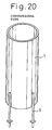
- a joining structure as shown in Fig. 22 or 23, has been conventionally used for a join, for instance, between a steel base structure and a foundation.
- the conventional joining structure is formed by welding a bolt connection base plate 11 to an end of a structural member 10 and reinforcing the joining structure with reinforcing ribs 12 attached between the structural member 10 and the base plate 11.
- the reinforcing ribs 12 are tabular members extending in the direction of the principal stress of the structural member 10 and are attached to protrude from the surface of the structural member 10 in the shape of a T.
- the present invention provides a joining structure composed of a structural member and one or more tabular members, or a structural member and anchor bolts, which joining structure can: solve the above-mentioned conventional problems; significantly alleviate the stress concentration at the toes of the tabular members such as the reinforcing ribs, etc.; greatly alleviate the residual stress caused by welding heat in the case of welding the tabular members; and, as a result, significantly improve the proof stress and the fatigue property compared with a conventional joining structure.
- the present invention is a joining structure having one or more tabular members protruding from the surface of a structural member and is characterized by bending one or both ends of each tabular member.
- one or both ends of each tabular member means one or both end portions of each tabular member where the tabular member contacts with a structural member which is a base material.
- the joining structure is a structure wherein a tabular member is a reinforcing rib protruding from the surface of a structural member in the shape of T so that the tabular member extends in the direction of the principal stress of the structural member and one or both ends of the reinforcing rib is/are bent in a direction deviating from the direction of said principal stress.
- one or both ends of a tabular member is/are bent in the shape of an gradual curve and to the extent that each bent end of the tabular member is formed at a right angle to the direction of the principal stress. Only one or both ends of a tabular member may be bent, or the whole body thereof may be bent in the shape of U or V.
- the structural member may have a coupling flange or a base plate.
- a tabular member may be placed between the structural member and the coupling flange or between the structural member and the base plate, or otherwise may be used for fixing a join member, or yet may be used for fixing a secondary member.
- the present invention is applicable also to a type of joining structure wherein anchor bolts extending in the direction of the principal stress of a structural member are welded to the surface of the structural member and an end of each anchor bolt is bent in a direction deviating from the direction of the principal stress.
- the rigidity at one or both ends of a tabular member decreases by bending the end(s) (toe(s)) of the tabular member such as a reinforcing rib, etc., preferably, in a direction deviating from the direction of the principal stress of a structural member.
- the stress concentration near the end(s) of the tabular member is significantly alleviated, and, when the tabular member is welded, the residual stress caused by welding heat near the end(s) of the tabular member is significantly alleviated as well.
- the proof stress and the fatigue property of the joining structure is largely improved compared with a conventional joining structure. Specific numerical values are explained later.
- each of the reinforcing ribs 3 is bent in the shape of U, but it extends, as a whole, in the direction of the principal stress of the structural member 1.
- the end (toe) 4, which is located opposite the coupling flange, of a reinforcing rib 3 is bent in the shape of an gradual curve and to the extent that the bent end of the reinforcing rib is formed at a right angle to the direction of the principal stress.
- the reinforcing ribs 3 are welded not only to the structural member 1 but also to the coupling flange 2, the welding to the coupling flange 2 being done by boxing welding. It is preferable to form a scallop at each of the inside corners of each reinforcing rib 3 to secure reliable welding work.
- the end 4 of a reinforcing rib 3 As the end 4 of a reinforcing rib 3 is bent in a direction deviating from the direction of the principal stress of the structural member 1, the end 4 of a reinforcing rib 3 can be formed into a low rigidity structure. As a result, not only the stress concentration at the end 4 of a reinforcing rib 3 but also the residual stress caused by welding heat of the welded portion are significantly alleviated and, thus, the proof stress and the fatigue property of the joining structure are significantly improved.
- the radius of curvature r of the end 4 of a reinforcing rib 3 is set at not less than 3 times its thickness t. If the radius of curvature r is smaller than 3 times of the thickness t, the material of the reinforcing rib 3 is likely to be deteriorated during bending the reinforcing rib 3 and, besides, the effect of lowering the rigidity decreases.
- the coupling flanges 2 of the first embodiment are coupled to each other using bolts 6 in the same manner as in a conventional flange coupling method. While there is no specific restriction as to the number and positions of the bolts 6, when each of the bolts is located between the two legs of each of the reinforcing ribs 3 bent into the shape of U as shown in Fig. 1, there is the advantage that the bolts are protected from physical impact from the outside and from a corrosive environment.
- the pipe constituting a structural member 1 is shown as a round steel pipe in any of relevant drawings, but it has to be noted that a square steel pipe may be used in place of the round pipe, or a section steel may be used as the structural member 1 as well.
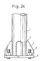
- the structural member 1 is a base structure consisting of a steel pipe
- numeral 5 indicates a base plate for fixing the structural member 1 to a foundation.
- Reinforcing ribs 3 bent into the shape of U are welded by T-joint weld between the structural member 1 and the base plate 5 so as to protrude in the shape of T, in the same manner as in the first embodiment.
- each of the reinforcing ribs 3 is cut slantwise so that its width becomes smaller towards the end 4, making the rigidity of the end 4 even smaller.
- the position of each bolt 6 to fix the base plate 5 to a foundation may be outside the legs of each reinforcing rib 3, as seen in the third embodiment shown in Fig. 3.
- the reinforcing ribs 3 disposed between the structural member 1 and the base plate 5 are formed into the shape of V.
- the legs of each reinforcing rib 3 slightly incline with respect to the direction of the principal stress of the structural member 1, but the centerline of the whole reinforcing rib 3 extends in the direction of the principal stress.
Applications Claiming Priority (5)
| Application Number | Priority Date | Filing Date | Title |
|---|---|---|---|
| JP23989499 | 1999-08-26 | ||
| JP23989499 | 1999-08-26 | ||
| JP2000173592 | 2000-06-09 | ||
| JP2000173592A JP3411888B2 (ja) | 1999-08-26 | 2000-06-09 | 接合構造体 |
| PCT/JP2000/005774 WO2001016438A1 (fr) | 1999-08-26 | 2000-08-25 | Corps structural accouple |
Publications (3)
| Publication Number | Publication Date |
|---|---|
| EP1213397A1 true EP1213397A1 (fr) | 2002-06-12 |
| EP1213397A4 EP1213397A4 (fr) | 2004-03-31 |
| EP1213397B1 EP1213397B1 (fr) | 2008-07-23 |
Family
ID=26534477
Family Applications (1)
| Application Number | Title | Priority Date | Filing Date |
|---|---|---|---|
| EP00955048A Expired - Lifetime EP1213397B1 (fr) | 1999-08-26 | 2000-08-25 | Corps structural accouple |
Country Status (8)
| Country | Link |
|---|---|
| US (1) | US6857808B1 (fr) |
| EP (1) | EP1213397B1 (fr) |
| JP (1) | JP3411888B2 (fr) |
| KR (1) | KR100487143B1 (fr) |
| CN (1) | CN1128269C (fr) |
| DE (1) | DE60039612D1 (fr) |
| ES (1) | ES2308991T3 (fr) |
| WO (1) | WO2001016438A1 (fr) |
Cited By (1)
| Publication number | Priority date | Publication date | Assignee | Title |
|---|---|---|---|---|
| CN102966839A (zh) * | 2012-11-19 | 2013-03-13 | 奇瑞汽车股份有限公司 | 一种避免在刚度突变处产生应力集中的方法 |
Families Citing this family (44)
| Publication number | Priority date | Publication date | Assignee | Title |
|---|---|---|---|---|
| JP4537621B2 (ja) * | 2001-06-19 | 2010-09-01 | 新日本製鐵株式会社 | 鋼管柱基部及び鋼管柱基部の強化方法 |
| JP4537622B2 (ja) * | 2001-06-19 | 2010-09-01 | 新日本製鐵株式会社 | 鋼管柱基部及び鋼管柱基部の強化方法 |
| JP2003253471A (ja) * | 2001-12-25 | 2003-09-10 | Nippon Steel Corp | 高耐食柱状構造物 |
| TWI273157B (en) | 2003-07-22 | 2007-02-11 | Nippon Steel Corp | Joining structure |
| CA2454776C (fr) * | 2003-12-31 | 2007-10-02 | Nippon Steel Corporation | Embase de poteau tubulaire en acier et methode de renforcement connexe |
| US7694487B1 (en) * | 2004-05-08 | 2010-04-13 | Ryan Gary L | Setting a tubular post for an electric fixture in soil |
| US7849659B2 (en) * | 2004-06-24 | 2010-12-14 | Kopshever Michael J Sr | Tower reinforcement apparatus and method |
| CN100482517C (zh) * | 2006-04-29 | 2009-04-29 | 中国国际海运集装箱(集团)股份有限公司 | 一种连接接头及带有该连接接头的车架主梁 |
| DE102007017876B4 (de) * | 2007-04-13 | 2021-06-24 | Sew-Eurodrive Gmbh & Co Kg | Ölfangvorrichtung, Getriebe und Verfahren |
| US20090016843A1 (en) * | 2007-07-13 | 2009-01-15 | Igor Komsitsky | Spacer Assemblies, Apparatus and Methods of Supporting Hardware |
| KR100811484B1 (ko) | 2007-09-21 | 2008-03-07 | 정해철 | 폐 합성수지를 이용한 지주 기초대 |
| USD599915S1 (en) * | 2007-11-26 | 2009-09-08 | Jerith Manufacturing Company, Inc. | Surface mount |
| US7694476B2 (en) * | 2008-02-29 | 2010-04-13 | Structural Components Llc | Systems and methods for in-line base plate termination in monopole structures |
| US20100024311A1 (en) * | 2008-07-30 | 2010-02-04 | Dustin Jon Wambeke | Wind turbine assembly with tower mount |
| US8056297B2 (en) * | 2008-09-25 | 2011-11-15 | General Electric Company | Flangeless wind tower |
| DK2256338T3 (en) * | 2008-11-03 | 2014-02-17 | Siemens Ag | Foundation, especially for a wind turbine and wind turbine |
| DE102009016503A1 (de) * | 2009-04-08 | 2010-10-14 | Rwe Ag | Ladesäulensockel für elektrische Ladesäulen |
| US8955284B2 (en) | 2009-12-02 | 2015-02-17 | Nippon Steel & Sumitomo Metal Coporation | Structure including a frame having four sides and a closed cross-section structural member |
| CN101929263A (zh) * | 2010-08-12 | 2010-12-29 | 湖北省电力勘测设计院 | 防断裂波型法兰 |
| GB2484672B (en) * | 2010-10-18 | 2013-10-16 | Claxton Engineering Services Ltd | Tower connector |
| ES2387143B1 (es) * | 2010-10-21 | 2013-04-15 | Europea De Construcciones Metalicas, S.A. | "conexion directa entre un tubo y un elemento plano" |
| US20120222380A1 (en) * | 2011-03-03 | 2012-09-06 | Wentworth Stuart H | Mount for connecting an article to a roof and method of use |
| US9138812B2 (en) * | 2011-08-28 | 2015-09-22 | Eric Stalemark | Deck mounting components for attachment of posts and the like |
| US20130114994A1 (en) * | 2011-11-04 | 2013-05-09 | Robert Erik Grip | Truss end pad fitting |
| US9574587B2 (en) | 2011-11-04 | 2017-02-21 | The Boeing Company | Preloading a fastener of a mechanical fitting |
| KR101409418B1 (ko) * | 2011-12-28 | 2014-06-19 | 재단법인 포항산업과학연구원 | 강관 소켓 및 이를 이용한 강관 말뚝과 강관 기둥의 연결 방법 |
| US9255409B2 (en) * | 2012-02-14 | 2016-02-09 | Construction Innovations Llc | Pole base bolt template |
| US9366462B2 (en) * | 2012-09-13 | 2016-06-14 | Emerson Climate Technologies, Inc. | Compressor assembly with directed suction |
| JP6188425B2 (ja) | 2013-05-29 | 2017-08-30 | 日立オートモティブシステムズ株式会社 | プロペラシャフト |
| US8757598B1 (en) * | 2013-06-28 | 2014-06-24 | Bradley Noel Jones | Hollow core post anchor |
| AU2013206749A1 (en) * | 2013-07-08 | 2015-01-22 | Outotec (Finland) Oy | Stress distribution element for a grinding mill shell |
| US20150056004A1 (en) * | 2013-08-23 | 2015-02-26 | Geoffrey Tyler Mitchell | Fatigue Resistant Structural Connection |
| NL2013138B1 (en) * | 2014-07-07 | 2016-09-09 | M & G Group B V | Adapter for a flue gas outlet. |
| US10428552B2 (en) * | 2015-07-30 | 2019-10-01 | William Sinclair | Post anchor |
| US9518402B1 (en) * | 2015-09-04 | 2016-12-13 | Kundel Industries, Inc. | Anchoring system |
| USD887026S1 (en) | 2018-04-12 | 2020-06-09 | P4 Infrastructure, Inc. | Mast base connector |
| USD930053S1 (en) * | 2018-05-04 | 2021-09-07 | Irobot Corporation | Debris container |
| US11236748B2 (en) | 2019-03-29 | 2022-02-01 | Emerson Climate Technologies, Inc. | Compressor having directed suction |
| US11767838B2 (en) | 2019-06-14 | 2023-09-26 | Copeland Lp | Compressor having suction fitting |
| US20210355702A1 (en) * | 2020-05-18 | 2021-11-18 | David M. Fisher | Headstone Support |
| US11248605B1 (en) | 2020-07-28 | 2022-02-15 | Emerson Climate Technologies, Inc. | Compressor having shell fitting |
| US11619228B2 (en) | 2021-01-27 | 2023-04-04 | Emerson Climate Technologies, Inc. | Compressor having directed suction |
| CN113802913B (zh) * | 2021-09-18 | 2022-08-12 | 国网安徽省电力有限公司经济技术研究院 | 一种输变电双钢管杆塔连接节点加固结构及其安装方法 |
| CN114016619A (zh) * | 2021-11-04 | 2022-02-08 | 西南石油大学 | 钢管柱新型法兰带内套筒拼接节点及力学性能分析方法 |
Citations (4)
| Publication number | Priority date | Publication date | Assignee | Title |
|---|---|---|---|---|
| US2146333A (en) * | 1938-02-02 | 1939-02-07 | Air Reduction | Welded structure |
| US3113760A (en) * | 1960-01-29 | 1963-12-10 | Locke Mfg Company | Interlocking ornamental railing |
| US4602463A (en) * | 1984-10-03 | 1986-07-29 | A. O. Smith Harvestore Products, Inc. | Tank construction having a floor formed of interconnected panels |
| JPH11117245A (ja) * | 1997-10-15 | 1999-04-27 | Nippon Steel Metal Prod Co Ltd | 防護柵用支柱 |
Family Cites Families (29)
| Publication number | Priority date | Publication date | Assignee | Title |
|---|---|---|---|---|
| US943747A (en) * | 1909-01-13 | 1909-12-21 | John F Hickman | Composite support for posts and poles. |
| US1539580A (en) * | 1921-07-14 | 1925-05-26 | Lally John | Building column |
| US2217055A (en) * | 1938-12-15 | 1940-10-08 | William F Jennens | Scaffold |
| US3436102A (en) * | 1966-09-23 | 1969-04-01 | Owens Corning Fiberglass Corp | Fitments for filament wound vessels |
| US3525495A (en) * | 1968-06-04 | 1970-08-25 | Louis Philippe Brosseau | Hanger assembly for suspended concrete forms |
| SE369099B (fr) * | 1971-12-17 | 1974-08-05 | R Haegglund | |
| JPS5322802B2 (fr) | 1972-07-21 | 1978-07-11 | ||
| JPS5077653A (fr) | 1973-11-21 | 1975-06-25 | ||
| JPS57129804A (en) | 1981-02-03 | 1982-08-12 | Toyo Soda Mfg Co Ltd | Recovering method for bromine |
| JPS5911987A (ja) | 1982-07-09 | 1984-01-21 | ヤマハ発動機株式会社 | 自動二輪車の後輪懸架装置 |
| JPS62135706A (ja) | 1985-12-09 | 1987-06-18 | Mitsutoyo Mfg Corp | 画像処理式測定装置 |
| JPS6341607A (ja) | 1986-08-08 | 1988-02-22 | Mazda Motor Corp | エンジンの動弁装置 |
| JPS6341607U (fr) * | 1986-08-29 | 1988-03-18 | ||
| US4825621A (en) * | 1987-12-10 | 1989-05-02 | Mitek Industries, Inc. | Holddown |
| US5481835A (en) * | 1989-05-12 | 1996-01-09 | Adian Engineering Corporation | Breakaway base and upper-separation joint |
| US5004366A (en) * | 1989-11-02 | 1991-04-02 | Simmons George H | Break-away coupling |
| US5205529A (en) * | 1991-08-02 | 1993-04-27 | Eaton Corporation | Friction-dampened gusset |
| JP2875106B2 (ja) | 1992-06-30 | 1999-03-24 | 敏郎 鈴木 | 構造部材の補強構造及び補強金具 |
| JP3392522B2 (ja) | 1994-07-04 | 2003-03-31 | 前田建設工業株式会社 | 鋼材と鉄板とのフレア部溶接方法 |
| US5467570A (en) * | 1994-10-12 | 1995-11-21 | Simpson Strong-Tie Co., Inc. | Tension tie |
| JPH08144381A (ja) | 1994-11-21 | 1996-06-04 | Nippon Chuzo Kk | アンカーボルト定着装置 |
| US5626434A (en) * | 1995-08-21 | 1997-05-06 | Cook; Robert W. | Connector for variable-curvature spaceframe structural system |
| US6073405A (en) * | 1995-12-22 | 2000-06-13 | Icf Kaiser Engineers, Inc. | Fitting for effecting bolted connection between a beam and a column in a steel frame structure |
| JPH09268653A (ja) | 1996-04-02 | 1997-10-14 | Hitachi Metals Ltd | 露出型鉄骨柱脚 |
| US5979130A (en) * | 1996-10-10 | 1999-11-09 | Simpson Strong-Tie Company, Inc. | Connector with concave seat |
| US5752781A (en) * | 1997-03-14 | 1998-05-19 | Adc Telecommunications, Inc. | Fiber trough coupling |
| US6032425A (en) * | 1998-02-09 | 2000-03-07 | Gugliotti Associates, Inc. | Flooring system |
| US6324800B1 (en) * | 1999-12-06 | 2001-12-04 | Portable Pipe Hangers, Inc. | Support base |
| US6427393B1 (en) * | 2001-01-26 | 2002-08-06 | Sinotech Engineering Consultants, Inc. | Seismic-resistant beam-to-column moment connection |
-
2000
- 2000-06-09 JP JP2000173592A patent/JP3411888B2/ja not_active Expired - Lifetime
- 2000-08-25 ES ES00955048T patent/ES2308991T3/es not_active Expired - Lifetime
- 2000-08-25 US US10/070,353 patent/US6857808B1/en not_active Expired - Lifetime
- 2000-08-25 EP EP00955048A patent/EP1213397B1/fr not_active Expired - Lifetime
- 2000-08-25 WO PCT/JP2000/005774 patent/WO2001016438A1/fr active IP Right Grant
- 2000-08-25 DE DE60039612T patent/DE60039612D1/de not_active Expired - Lifetime
- 2000-08-25 KR KR10-2002-7002449A patent/KR100487143B1/ko active IP Right Grant
- 2000-08-25 CN CN00812105A patent/CN1128269C/zh not_active Expired - Lifetime
Patent Citations (4)
| Publication number | Priority date | Publication date | Assignee | Title |
|---|---|---|---|---|
| US2146333A (en) * | 1938-02-02 | 1939-02-07 | Air Reduction | Welded structure |
| US3113760A (en) * | 1960-01-29 | 1963-12-10 | Locke Mfg Company | Interlocking ornamental railing |
| US4602463A (en) * | 1984-10-03 | 1986-07-29 | A. O. Smith Harvestore Products, Inc. | Tank construction having a floor formed of interconnected panels |
| JPH11117245A (ja) * | 1997-10-15 | 1999-04-27 | Nippon Steel Metal Prod Co Ltd | 防護柵用支柱 |
Non-Patent Citations (2)
| Title |
|---|
| PATENT ABSTRACTS OF JAPAN vol. 1999, no. 09, 30 July 1999 (1999-07-30) & JP 11 117245 A (NIPPON STEEL METAL PROD CO LTD; KAWASAKI STEEL METAL PRODUCTS & EN), 27 April 1999 (1999-04-27) * |
| See also references of WO0116438A1 * |
Cited By (2)
| Publication number | Priority date | Publication date | Assignee | Title |
|---|---|---|---|---|
| CN102966839A (zh) * | 2012-11-19 | 2013-03-13 | 奇瑞汽车股份有限公司 | 一种避免在刚度突变处产生应力集中的方法 |
| CN102966839B (zh) * | 2012-11-19 | 2015-12-09 | 奇瑞汽车股份有限公司 | 一种避免在刚度突变处产生应力集中的方法 |
Also Published As
| Publication number | Publication date |
|---|---|
| JP2001132102A (ja) | 2001-05-15 |
| DE60039612D1 (de) | 2008-09-04 |
| KR100487143B1 (ko) | 2005-05-03 |
| ES2308991T3 (es) | 2008-12-16 |
| CN1371444A (zh) | 2002-09-25 |
| WO2001016438A1 (fr) | 2001-03-08 |
| EP1213397B1 (fr) | 2008-07-23 |
| JP3411888B2 (ja) | 2003-06-03 |
| CN1128269C (zh) | 2003-11-19 |
| US6857808B1 (en) | 2005-02-22 |
| EP1213397A4 (fr) | 2004-03-31 |
| KR20020059589A (ko) | 2002-07-13 |
Similar Documents
| Publication | Publication Date | Title |
|---|---|---|
| US6857808B1 (en) | Joining structure | |
| US7360969B2 (en) | Z-shaped sheet piling | |
| US6185897B1 (en) | Flange connector | |
| CN108330823A (zh) | 装配式钢混组合梁桥桥面板纵缝连接构造及施工方法 | |
| JPH09511298A (ja) | 二重外枠複合構造体の改良およびその構造体に関する改良 | |
| JP4347158B2 (ja) | 鋼橋、並びに鋼橋の補強方法及び補修方法 | |
| US7182543B2 (en) | Joining structure | |
| KR102276624B1 (ko) | 사선형 내다이어프램이 설치된 cft 기둥구조 | |
| JP5682960B2 (ja) | 鋼構造物の補強構造及び補強方法 | |
| KR100910163B1 (ko) | 커튼월 고정용 브래킷 | |
| US11448192B2 (en) | Support structure for a wind turbine | |
| JP4031682B2 (ja) | 接合構造体 | |
| JP4138426B2 (ja) | 鉄塔の基礎構造 | |
| KR102271672B1 (ko) | 한계상태설계법에 적합한 구조성능을 갖는 체결형 거더 | |
| JP4035843B2 (ja) | 接合構造体 | |
| JP4091870B2 (ja) | 床スラブ合成機能を有する柱・梁の接合構造 | |
| JP2009030357A (ja) | 柱と梁の溶接接合構造 | |
| KR101747959B1 (ko) | 이중웨브 조립보 | |
| JPH1046678A (ja) | 鋼製折れ梁 | |
| CN110714535A (zh) | 一种三维装配式梁柱节点结构 | |
| JP7360039B2 (ja) | 鋼矢板壁および鋼矢板壁の製造方法 | |
| JP3434427B2 (ja) | 鉄筋コンクリート建造物の貫通孔補強具 | |
| JP2008101419A (ja) | 鋼管柱とフラットスラブの接合部 | |
| KR200268181Y1 (ko) | 도로교량용 강재 박스 거더의 거셋 플레이트부 구조 | |
| KR200294215Y1 (ko) | 리브와 도그본 및 부분용접을 이용한 철골용보-기둥접합장치 |
Legal Events
| Date | Code | Title | Description |
|---|---|---|---|
| PUAI | Public reference made under article 153(3) epc to a published international application that has entered the european phase |
Free format text: ORIGINAL CODE: 0009012 |
|
| 17P | Request for examination filed |
Effective date: 20020322 |
|
| AK | Designated contracting states |
Kind code of ref document: A1 Designated state(s): DE ES FR GB IT |
|
| AX | Request for extension of the european patent |
Free format text: AL;LT;LV;MK;RO;SI |
|
| RIN1 | Information on inventor provided before grant (corrected) |
Inventor name: OKIMOTO, MASAYUKI, C/O NIPPON STEEL CORPORATION Inventor name: HIGASA, MASAFUMI, INABA ELECTRIC WORK Inventor name: KONDO, TETSUMI, NIPPON STEEL CORPORATION Inventor name: SUGIMOTO, MASAKAZU, NIPPON STEEL CORPORATION Inventor name: KITA, SHIRO, YOSHIMOTO POLE CO., LTD. |
|
| A4 | Supplementary search report drawn up and despatched |
Effective date: 20040216 |
|
| RBV | Designated contracting states (corrected) |
Designated state(s): DE ES FR GB IT |
|
| 17Q | First examination report despatched |
Effective date: 20041105 |
|
| 17Q | First examination report despatched |
Effective date: 20041105 |
|
| GRAP | Despatch of communication of intention to grant a patent |
Free format text: ORIGINAL CODE: EPIDOSNIGR1 |
|
| GRAS | Grant fee paid |
Free format text: ORIGINAL CODE: EPIDOSNIGR3 |
|
| GRAA | (expected) grant |
Free format text: ORIGINAL CODE: 0009210 |
|
| AK | Designated contracting states |
Kind code of ref document: B1 Designated state(s): DE ES FR GB IT |
|
| REG | Reference to a national code |
Ref country code: GB Ref legal event code: FG4D |
|
| REF | Corresponds to: |
Ref document number: 60039612 Country of ref document: DE Date of ref document: 20080904 Kind code of ref document: P |
|
| REG | Reference to a national code |
Ref country code: ES Ref legal event code: FG2A Ref document number: 2308991 Country of ref document: ES Kind code of ref document: T3 |
|
| PLBE | No opposition filed within time limit |
Free format text: ORIGINAL CODE: 0009261 |
|
| STAA | Information on the status of an ep patent application or granted ep patent |
Free format text: STATUS: NO OPPOSITION FILED WITHIN TIME LIMIT |
|
| 26N | No opposition filed |
Effective date: 20090424 |
|
| PG25 | Lapsed in a contracting state [announced via postgrant information from national office to epo] |
Ref country code: IT Free format text: LAPSE BECAUSE OF NON-PAYMENT OF DUE FEES Effective date: 20080825 |
|
| PGRI | Patent reinstated in contracting state [announced from national office to epo] |
Ref country code: IT Effective date: 20110616 |
|
| REG | Reference to a national code |
Ref country code: DE Ref legal event code: R082 Ref document number: 60039612 Country of ref document: DE Representative=s name: VOSSIUS & PARTNER, DE |
|
| REG | Reference to a national code |
Ref country code: DE Ref legal event code: R081 Ref document number: 60039612 Country of ref document: DE Owner name: NIPPON STEEL SUMITOMO METAL CORPORATION, JP Free format text: FORMER OWNERS: YOSHIMOTO POLE CO., LTD., TOKIO/TOKYO, JP; INABA ELECTRIC WORK, KASHIWABARA, JP; NIPPON STEEL CORP., TOKIO/TOKYO, JP Effective date: 20130422 Ref country code: DE Ref legal event code: R082 Ref document number: 60039612 Country of ref document: DE Representative=s name: VOSSIUS & PARTNER, DE Effective date: 20130422 Ref country code: DE Ref legal event code: R081 Ref document number: 60039612 Country of ref document: DE Owner name: NIPPON STEEL & SUMITOMO METAL CORPORATION, JP Free format text: FORMER OWNER: YOSHIMOTO POLE CO., LTD., INABA ELECTRIC WORK, NIPPON STEEL CORP., , JP Effective date: 20130422 Ref country code: DE Ref legal event code: R081 Ref document number: 60039612 Country of ref document: DE Owner name: YOSHIMOTO POLE CO., LTD., JP Free format text: FORMER OWNER: YOSHIMOTO POLE CO., LTD., INABA ELECTRIC WORK, NIPPON STEEL CORP., , JP Effective date: 20130422 Ref country code: DE Ref legal event code: R081 Ref document number: 60039612 Country of ref document: DE Owner name: INABA ELECTRIC WORK, JP Free format text: FORMER OWNER: YOSHIMOTO POLE CO., LTD., INABA ELECTRIC WORK, NIPPON STEEL CORP., , JP Effective date: 20130422 Ref country code: DE Ref legal event code: R082 Ref document number: 60039612 Country of ref document: DE Representative=s name: VOSSIUS & PARTNER PATENTANWAELTE RECHTSANWAELT, DE Effective date: 20130422 Ref country code: DE Ref legal event code: R081 Ref document number: 60039612 Country of ref document: DE Owner name: INABA ELECTRIC WORK, JP Free format text: FORMER OWNERS: YOSHIMOTO POLE CO., LTD., TOKIO/TOKYO, JP; INABA ELECTRIC WORK, KASHIWABARA, JP; NIPPON STEEL CORP., TOKIO/TOKYO, JP Effective date: 20130422 Ref country code: DE Ref legal event code: R081 Ref document number: 60039612 Country of ref document: DE Owner name: NIPPON STEEL & SUMITOMO METAL CORPORATION, JP Free format text: FORMER OWNERS: YOSHIMOTO POLE CO., LTD., TOKIO/TOKYO, JP; INABA ELECTRIC WORK, KASHIWABARA, JP; NIPPON STEEL CORP., TOKIO/TOKYO, JP Effective date: 20130422 Ref country code: DE Ref legal event code: R081 Ref document number: 60039612 Country of ref document: DE Owner name: YOSHIMOTO POLE CO., LTD., JP Free format text: FORMER OWNERS: YOSHIMOTO POLE CO., LTD., TOKIO/TOKYO, JP; INABA ELECTRIC WORK, KASHIWABARA, JP; NIPPON STEEL CORP., TOKIO/TOKYO, JP Effective date: 20130422 |
|
| REG | Reference to a national code |
Ref country code: FR Ref legal event code: CD Owner name: NIPPON STEEL & SUMITOMO METAL CORPORATION, JP Effective date: 20130913 Ref country code: FR Ref legal event code: CA Effective date: 20130913 |
|
| REG | Reference to a national code |
Ref country code: FR Ref legal event code: PLFP Year of fee payment: 17 |
|
| REG | Reference to a national code |
Ref country code: FR Ref legal event code: PLFP Year of fee payment: 18 |
|
| REG | Reference to a national code |
Ref country code: FR Ref legal event code: PLFP Year of fee payment: 19 |
|
| REG | Reference to a national code |
Ref country code: DE Ref legal event code: R082 Ref document number: 60039612 Country of ref document: DE Representative=s name: VOSSIUS & PARTNER PATENTANWAELTE RECHTSANWAELT, DE Ref country code: DE Ref legal event code: R081 Ref document number: 60039612 Country of ref document: DE Owner name: NIPPON STEEL CORPORATION, JP Free format text: FORMER OWNERS: INABA ELECTRIC WORK, KASHIWABARA, JP; NIPPON STEEL & SUMITOMO METAL CORPORATION, TOKYO, JP; YOSHIMOTO POLE CO., LTD., TOKIO/TOKYO, JP Ref country code: DE Ref legal event code: R081 Ref document number: 60039612 Country of ref document: DE Owner name: YOSHIMOTO POLE CO., LTD., JP Free format text: FORMER OWNERS: INABA ELECTRIC WORK, KASHIWABARA, JP; NIPPON STEEL & SUMITOMO METAL CORPORATION, TOKYO, JP; YOSHIMOTO POLE CO., LTD., TOKIO/TOKYO, JP Ref country code: DE Ref legal event code: R081 Ref document number: 60039612 Country of ref document: DE Owner name: INABA ELECTRIC WORK, JP Free format text: FORMER OWNERS: INABA ELECTRIC WORK, KASHIWABARA, JP; NIPPON STEEL & SUMITOMO METAL CORPORATION, TOKYO, JP; YOSHIMOTO POLE CO., LTD., TOKIO/TOKYO, JP |
|
| PGFP | Annual fee paid to national office [announced via postgrant information from national office to epo] |
Ref country code: DE Payment date: 20190813 Year of fee payment: 20 Ref country code: ES Payment date: 20190903 Year of fee payment: 20 Ref country code: FR Payment date: 20190711 Year of fee payment: 20 Ref country code: IT Payment date: 20190821 Year of fee payment: 20 |
|
| PGFP | Annual fee paid to national office [announced via postgrant information from national office to epo] |
Ref country code: GB Payment date: 20190822 Year of fee payment: 20 |
|
| REG | Reference to a national code |
Ref country code: DE Ref legal event code: R071 Ref document number: 60039612 Country of ref document: DE |
|
| REG | Reference to a national code |
Ref country code: GB Ref legal event code: PE20 Expiry date: 20200824 |
|
| PG25 | Lapsed in a contracting state [announced via postgrant information from national office to epo] |
Ref country code: GB Free format text: LAPSE BECAUSE OF EXPIRATION OF PROTECTION Effective date: 20200824 |
|
| REG | Reference to a national code |
Ref country code: ES Ref legal event code: FD2A Effective date: 20201202 |
|
| PG25 | Lapsed in a contracting state [announced via postgrant information from national office to epo] |
Ref country code: ES Free format text: LAPSE BECAUSE OF EXPIRATION OF PROTECTION Effective date: 20200826 |