EP1213226A2 - Wiederverschliessbare, quaderförmige Faltschachtel - Google Patents
Wiederverschliessbare, quaderförmige Faltschachtel Download PDFInfo
- Publication number
- EP1213226A2 EP1213226A2 EP01126177A EP01126177A EP1213226A2 EP 1213226 A2 EP1213226 A2 EP 1213226A2 EP 01126177 A EP01126177 A EP 01126177A EP 01126177 A EP01126177 A EP 01126177A EP 1213226 A2 EP1213226 A2 EP 1213226A2
- Authority
- EP
- European Patent Office
- Prior art keywords
- side wall
- folding box
- tab
- flap
- rear side
- Prior art date
- Legal status (The legal status is an assumption and is not a legal conclusion. Google has not performed a legal analysis and makes no representation as to the accuracy of the status listed.)
- Withdrawn
Links
- 239000000463 material Substances 0.000 claims description 18
- 230000003313 weakening effect Effects 0.000 claims description 9
- 239000000725 suspension Substances 0.000 description 36
- 238000004026 adhesive bonding Methods 0.000 description 7
- 206010053648 Vascular occlusion Diseases 0.000 description 6
- 238000007789 sealing Methods 0.000 description 6
- 238000004519 manufacturing process Methods 0.000 description 4
- 239000000853 adhesive Substances 0.000 description 3
- 230000001070 adhesive effect Effects 0.000 description 3
- 239000000428 dust Substances 0.000 description 3
- 238000004806 packaging method and process Methods 0.000 description 3
- 230000015572 biosynthetic process Effects 0.000 description 2
- 230000007613 environmental effect Effects 0.000 description 2
- 238000000034 method Methods 0.000 description 2
- 239000002245 particle Substances 0.000 description 2
- 238000004080 punching Methods 0.000 description 2
- 239000002699 waste material Substances 0.000 description 2
- 208000030922 Tibial Meniscus injury Diseases 0.000 description 1
- 238000010276 construction Methods 0.000 description 1
- 238000005520 cutting process Methods 0.000 description 1
- 230000006735 deficit Effects 0.000 description 1
- 238000003780 insertion Methods 0.000 description 1
- 230000037431 insertion Effects 0.000 description 1
- 230000003287 optical effect Effects 0.000 description 1
- 239000011505 plaster Substances 0.000 description 1
- 238000003825 pressing Methods 0.000 description 1
- 230000000007 visual effect Effects 0.000 description 1
Images







Classifications
-
- B—PERFORMING OPERATIONS; TRANSPORTING
- B65—CONVEYING; PACKING; STORING; HANDLING THIN OR FILAMENTARY MATERIAL
- B65D—CONTAINERS FOR STORAGE OR TRANSPORT OF ARTICLES OR MATERIALS, e.g. BAGS, BARRELS, BOTTLES, BOXES, CANS, CARTONS, CRATES, DRUMS, JARS, TANKS, HOPPERS, FORWARDING CONTAINERS; ACCESSORIES, CLOSURES, OR FITTINGS THEREFOR; PACKAGING ELEMENTS; PACKAGES
- B65D5/00—Rigid or semi-rigid containers of polygonal cross-section, e.g. boxes, cartons or trays, formed by folding or erecting one or more blanks made of paper
- B65D5/42—Details of containers or of foldable or erectable container blanks
- B65D5/44—Integral, inserted or attached portions forming internal or external fittings
- B65D5/46—Handles
- B65D5/46072—Handles integral with the container
- B65D5/46088—Handles integral with the container formed by extensions of closure flaps, by closure flaps or by extensions of side flaps of a container formed by folding a blank to form a tubular body
-
- B—PERFORMING OPERATIONS; TRANSPORTING
- B65—CONVEYING; PACKING; STORING; HANDLING THIN OR FILAMENTARY MATERIAL
- B65D—CONTAINERS FOR STORAGE OR TRANSPORT OF ARTICLES OR MATERIALS, e.g. BAGS, BARRELS, BOTTLES, BOXES, CANS, CARTONS, CRATES, DRUMS, JARS, TANKS, HOPPERS, FORWARDING CONTAINERS; ACCESSORIES, CLOSURES, OR FITTINGS THEREFOR; PACKAGING ELEMENTS; PACKAGES
- B65D5/00—Rigid or semi-rigid containers of polygonal cross-section, e.g. boxes, cartons or trays, formed by folding or erecting one or more blanks made of paper
- B65D5/42—Details of containers or of foldable or erectable container blanks
- B65D5/54—Lines of weakness to facilitate opening of container or dividing it into separate parts by cutting or tearing
- B65D5/5405—Lines of weakness to facilitate opening of container or dividing it into separate parts by cutting or tearing for opening containers formed by erecting a blank in tubular form
- B65D5/542—Lines of weakness to facilitate opening of container or dividing it into separate parts by cutting or tearing for opening containers formed by erecting a blank in tubular form the lines of weakness being provided in the container body
- B65D5/5425—Lines of weakness to facilitate opening of container or dividing it into separate parts by cutting or tearing for opening containers formed by erecting a blank in tubular form the lines of weakness being provided in the container body and defining after rupture a lid hinged to the upper edge of the container body
Definitions
- the invention relates to a reclosable, rectangular folding box with a front side wall, a rear side wall, one the front side wall and the right side wall connecting the rear side wall and a left side wall Side wall, one formed in particular by four bottom locking tabs
- Bottom closure, an upper closure, with two bottom closure tabs can be glued together, with an integrated in the rear side wall Tear-off flap, which by means of a weakening or breaking line in the rear Sidewall is held.
- DE 39 32 441 A1 discloses a reclosable folding box, which consists of a front and a rear side wall and two side walls connecting the front and rear side wall, a bottom part and an upper closing flap, the closing flap being connected to an insertion tongue via a fastening tab, which in turn is arranged over a line of weakness in the rear or front side wall and can be broken out of it.
- this folding box offers no possibility of hanging it on a hook in any way. After this carton has been filled with the goods to be sold, it must be presented to the customer in the most convenient and manageable manner. A very clear method of the offer is possible by means of the well-known self-service hooks on sales shelves, which allow the inclusion of several folding boxes arranged one behind the other.
- a correspondingly shaped blank must also be attached to the folding box with a hanging device. This is usually done by gluing this part with the appropriate suspension device to the folding box at a suitable point in an additional operation.
- the manufacturing process of the folding box is complicated, among other things, by producing the further cut or gluing it to the finished box and being extended in time by several work steps, and this also means a much higher expenditure on equipment.
- DE 43 22 555 A1 also shows a reclosable, rectangular folding box.
- This folding box consists of a rear side wall formed by an outer side wall part and an inner side wall part, a front side wall, two side walls connecting the front and the rear side wall, a bottom closure and an upper closure, the outer side wall part having a hanging flap in its upper region a correspondingly shaped suspension device, such as round or slot perforations.
- the folding box can be placed on a hook using the hanging tab.
- the hanging flap is made of only one layer and consists of the same material as the rest of the folding box, problems arise in practical use of the folding box. If the folding box is made of thin material, taking into account environmental and cost aspects, the hanging tab has insufficient stability. Even if the folding box is pulled gently and unintentionally, the hanging flap tears out, so that the hanging flap loses its function and the box can no longer be hung up as desired. In addition, the box becomes unsightly and can no longer be presented to the customer.
- No. 4,344,533 describes a box which has a hanger which is composed of two individual hanging tabs.
- this box has some disadvantages in its manufacture and use.
- the blank of the box disclosed in the American patent has a vertical structure, that is, the two hanging tabs and the end tab, which together form the hanger of the box, are arranged in a straight line with the four side walls, the individual parts each with one Fold line are connected to each other.
- This type of folding cut means that after the body of the box has been assembled, it is only possible to fill it laterally and not, as is customary and desirable, from above. This requires the use of cartoning and filling machines that are specially designed for this cutting, otherwise rather unusual.
- the simultaneous use of the hanger as a closure lid for the box means that when the box is still sealed, especially if the box has a large structural depth, a large, bulky hanger is formed, which, for example, leads to the box being hung up on a shelf takes up a lot of floor space, so that the actual capacity of the shelf with the disclosed boxes can only be used insufficiently.
- the folding box consists of a front side wall, a rear side wall, a right side wall connecting the front and rear side walls and a left side wall.
- the box has a bottom closure formed by four bottom closure tabs and an upper closure formed by four closure tabs, two closure tabs of the top closure and two bottom closure tabs being glued together.
- a tear-open tab is integrated in the front side wall or in the rear side wall, which is held by means of a weakening or predetermined breaking line in the front side wall or the rear side wall and which is connected via a fold line to a closing tab of the upper closure or to a bottom closing tab of the bottom closure is.
- At least one inner rear wall is provided in the folding box, specifically when the tear tab is in the rear side wall. If it is the case that the tear-open tab is located in the front side wall, then an intermediate wall and, connected to the intermediate wall, an inner front wall are articulated.
- a first hanging tab with a hanging device, such as slotted or round perforations, is articulated to the rear side wall in its area without the pull tabs, which lies in the plane formed by the rear side wall.
- a second hanging tab with a hanging device such as slotted or round perforations, is punched out of the same area of the inner rear wall as for the rear side wall and starting from the fold line between the inner rear wall and the closing flap, the closing flap articulated on the inner rear wall having a greater width on the folding line has as the second hanging tab.
- This folding box has a double-layer hanger, but has no tamper-evident closure that is resealable.
- a disadvantage of all boxes known from the prior art is that, if these have the tamper-evident seal disclosed in DE 43 22 555 A1, which Hanger always on the side of the tamper evident closure Folding box is present, i.e. in the bottom area of the folding box if it is the above-mentioned folding boxes around folding boxes with a one-piece cut is.
- a subsequent attachment of a hanger to the box is from the Always avoid the reasons given above.
- the buyer is irritated by the arrangement of the hanger of the folding box and the closure on opposite sides of the folding box.
- Experience has shown that the latter takes the folding box in his hand and opens the folding box at the top, i.e. near the hanger, by irreversibly tearing open and destroying the folding box. A subsequent closing of this is no longer possible.
- the more experienced customer opens the folding box as intended at the tamper-evident closure, removes the desired product, for example a plaster, and then closes the box again. If you hang this on the hanger on a hook, the closed lock is at the bottom. It can therefore not be ruled out that the folding box may open unintentionally and the products in it may fall out.
- a second problem with the folding box known from DE 43 22 555 A1 is that a fifth wall lying inside the folding box is always required to form the tamper-evident closure, which means that additional material is required. This wall results in a more complicated cut with larger waste, furthermore this wall increases the material costs. Finally, the wall increases the weight of the folding box to be disposed of.
- the invention aims to solve the problems described.
- the invention has for its object a resealable, cuboid
- the under possible low material use has a high stability, which using as little material as possible can be produced inexpensively using machines can be erected, filled and closed easily and quickly and their Folded blank consists of a single piece.
- the invention comprises a punch blank folding box according to the invention.
- the cuboid folding box resealable according to the invention is made accordingly from a front side wall, a rear side wall, one the front side wall and the right side wall connecting the rear side wall and a left side wall.
- the folding box has one of four in particular Bottom closure tab formed bottom closure and an upper closure, where two bottom locking tabs can be glued together. Furthermore, in a tear tab is integrated into the rear side wall, which by means of a A line of weakness or predetermined breaking is held in the rear side wall.
- the structure of the folding box is similar to one in the preferred embodiment Structure as described in ECMA code A 1020 (see “THE ECMA CODE of FOLDING CARTON STYLES ", published by ECMA (European Carton Makers Association), Reprint January 2000) is known.
- the hanging tabs between the front side wall and arranged the lid portion Preferably, the hanging tabs between the front side wall and arranged the lid portion.
- the front side wall as well the first hanging tab without a dividing fold line into a single wall be summarized.
- the hanging tabs are between the Lid section and the tab arranged.
- the second Hanging flap and the flap without separating fold line to a single wall be summarized.
- the hanging tabs share the Lid section in two parts.
- the lid section is particularly preferred hanging within a sales shelf divided in the middle by the hanging brackets.
- the Dimensions of the first and second hanging tab match that
- the suspension device in the first suspension bracket advantageously has larger ones Dimensions on as the hanger in the second hanger, and to ensure that despite the folding of the carton not too avoiding inaccuracy the specifications for the dimensions of the opening that from the suspension devices, which may not be completely superimposed is formed, fulfilled.
- the two hanging tabs can still be glued to one another the stability of the hanger formed from the two hanging brackets Increase folding box.
- first and optionally the second hanging tab on the respective fold lines are given greater flexibility so that the hanging tabs can be bent more easily mentioned fold lines can be provided over their entire length or only in sections knife-like punchings.
- the fold line between the first hanging flap and the second hanging flap can be provided with punch-like punchings.
- the cover section particularly preferably covers the surface of the tear tab completely.
- the tear-open tab is therefore not visible after the first opening of the folding box below the lid section, so that the visual impression of the folding box is not clouded.
- this embodiment has the advantage that the gap present in the rear side wall after removal of the tear-open tab is completely closed by the cover section when this is guided under the rear side wall to close the folding box.
- the tear tab does not extend over the entire width of the rear side wall. Rather, the pull tab is made narrower, in such a way that in addition to the pull tab in the upper region of the rear side wall there are webs which, after the removal of the pull tab from the rear side wall, ensure increased stability of the rear side wall and thus the entire folding box.
- the folding box has a tamper-evident seal under the visible flap. This tamper-evident closure is created in that the surface of the underside of the lid section forms a unit created by gluing with the perforated tear-open flap on the body of the folding box.
- This perforated tear-open flap lies below the glued-in insert flap on top of it and is perforated so that when the folding box is opened for the first time, it is separated from the body of the folding box by lightly pressing in the two superimposed surfaces that are glued together.
- the folding box can be reclosed by reinserting the lid section. The product can be removed after opening the folding box.
- a further closure flap which is located in the extension of the rear side wall, can be hinged to the tear-open flap via a fold line.
- the flap is folded over 90 °, placed on the flap and glued to it. In this way, the pressure rigidity of the folding box increases in such a way that sinking in of the upper closure of the folding box can be ruled out.
- the reclosable, cuboid folding box is particularly advantageous use for packaging flat objects, especially one or several plasters.
- the invention relates to the punch blank for producing a in the Folded box marked claims.
- the advantage of this folding box is that the closure of the folding box and the hanger formed from the hanging tabs are attached to one side of the folding box. There are also other advantages, such that an unauthorized opening of the box can be recognized immediately when the original packaging is closed.
- the folding box is machine-compatible; it is glued as a flat blank, erected by the cartoner and transported to the filling station, the hanging flap being already formed on the folding box.
- the front and back of the folding box offer excellent design options. After the folding box has been erected and filled, the head area and the central area can be easily glued. This bonding provides good dust protection, so that subsequent full wrapping or additional packaging of the folding box is not necessary.
- the folding box is glued, dust-protected, originally closed and resealable; it is easy to handle and variable. A problem-free processing is possible.
- the folding box is also environmentally friendly and is made from a folding blank with a minimum material consumption.
- a hanger is formed on the folding box, which is composed of two hanging tabs - and therefore two layers of material.
- This has the advantage that the hanger is characterized by great stability, so that it can withstand greater tensile stresses without fear of tearing out.
- the two hanging brackets are glued together, a firm bond is created, which can also be designed to be visually appealing.
- the walls of the folding box are otherwise made of one layer, with the exception of the intended bonding points. In this way, very little material is used overall for the design of the folding box, and yet a resilient hanger is formed.
- the punched blank 10 of the folding box 1 is shown in FIG.
- the die cut blank 10 can be made of cardboard, cardboard or another suitable material.
- the body of the erected folding box 1 is formed by the front side wall 11, the rear side wall 12, the right side wall 13 connecting the front side wall 11 and the rear side wall 12 and the left side wall 14.
- the tear-open tab 40 provided for opening the folding box 1 is held in the rear side wall 12 by means of a weakening or predetermined breaking line 41, specifically in the area of the upper closure 30.
- a flap 16 is articulated to the rear side wall 12, it being possible for the flap 16 to be glued to the left side wall 14 in order to permanently close the body.
- All side walls 11, 12, 13, 14 are rectangular, but the front ones Side wall 11 and rear side wall 12, which are preferably the same Have dimensions, slightly wider than the other two side walls 13, 14, the also preferably have identical dimensions.
- the tab 16 is one way wide, that a secure gluing with the left side wall 14 is possible, and others as wide as the two side walls 13, 14.
- the individual side walls 11, 12, 13, 14 and the tab 16 are over corresponding fold lines 101, 102, 103, 104 connected to one another.
- the bottom closure 20 is composed of the four bottom closure tabs 21, 22, 23, 24, which are linked by means of fold lines 201, 202, 203, 204 to the corresponding side walls 11, 12, 13, 14.
- the bottom flap 21, which is articulated on the front side wall 11, and the bottom flap 22 articulated on the rear side wall 12 via the fold line 202 preferably have a rectangular shape.
- the length or height of the two flaps 21, 22 advantageously correspond approximately to the width of the two narrower side walls 13, 14, so that when the folding box 1 is erected, the bottom flaps 21, 22 folded inward at an angle of 90 ° overlap, which advantageously are glued together, which provides increased protection of the bottom closure 20 against the ingress of dust or other dirt particles.
- two further bottom locking tabs 23, 24 are articulated via the fold lines 203, 204, which taper towards their free end and which have an essentially trapezoidal design.
- the upper closure 30 is composed of an upper closure flap 31, which is articulated on the front side wall 11 via the fold line 301, and of two closure flaps 33, 34, which are correspondingly linked to the side walls 13, 14 via the fold lines 303, 304 are.
- the two locking tabs 33, 34 preferably have the same shape and dimension as the two bottom locking tabs 23, 24.
- the lid portion 311, which is hinged to the front side wall 11, preferably has a rectangular shape.
- the length or height of the lid section 311 advantageously corresponds approximately to the dimensions of the bottom locking tabs 21, 22.
- On the two narrow side walls 13, 14 two further flaps 33, 34 are articulated via the fold lines 303, 304, which taper towards their free end and which have an essentially trapezoidal design.
- the tab 314, which is articulated on the lid section 311, extends over the entire width of the front side wall 11.
- the tab 314 covers the tear tab 40 completely in terms of area, so that the tear tab 40 lies below the tab 314 and does not close from the outside there see is.
- the substantially rectangular pull tab 40 provided by an appropriately attached weakening or The predetermined breaking line 41 is easily broken out of the rear side wall 12 can.
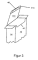
- the tab 314, which is on the outside the pull tab 40 is glued, pulled so that the weakening or Break line 41 separated and the tear tab 40 from the rear side wall 12 taken and together with the tab 314, for example 90 ° on the fold line 301 is folded back.
- the tab 314 is in the folding box 1 inserted, directly under the rear side wall 12.
- Figures 2 and 3 is the fully assembled and closed Folding box 1 shown in the area of the upper closure 30, on the one hand before opening for the first time and on the other hand after opening for the first time.
- the body of the folding box 1 is erected.
- the lid section 311 closes the folding box 1 from above, the tab 314 is glued to the tear tab 40 so that it is completely covered.
- the folding box 1 can therefore not be opened without being damaged.
- FIG. 3 shows - the weakening or Break line 41 is separated, so that the tear tab 40 with the tab 314 after can be performed above.
- the flaps 33, 34 are opened after.
- the flat, unglued die cut is an alternative executed folding box 1 shown in the area of the upper closure 30 with is provided with a hanger.
- the closure flap 31 is articulated on the front side wall 11 on the one hand via a fold line 301 and, on the other hand, the bottom closure flap 21 is articulated on the opposite side via a fold line 201, the closure flap 31 being composed of a first section 3111 of the cover section 311, which is articulated via a fold line 301 on the front side wall 11, a first suspension tab 312 with a suspension device 35, which is articulated via a fold line 305 to the first section 3111, a second suspension tab 313 with a suspension device 36 which is linked via a fold line 306 to the first Suspension tab 312 is articulated, a second cover section 3112, which is articulated on the second suspension tab 313 via a fold line 307, the tab 314, which is articulated on the second cover section 3112 via the fold line 302.
- the sum of the widths of the two lid sections 3111 and 3112 corresponds approximately to the width of the two bottom closure tabs 21, 22.
- the flaps 33, 34 are first folded inwards at an angle of 90 °.
- the flap 31 will unfolded so that the two cover sections 3111 and 3112 parallel to each other are aligned and form the lid surface of the folding box 1.
- the first hanging tab 312 which has a substantially rectangular shape, advantageously has a hanging device 35 centrally in the center of the area, which preferably represents a combination of slot and round perforations, so that the generally preferred shape for such recesses, the so-called euro hole, results. which enables a secure, but at the same time flexible placement of the filled folding box 1 on a sales shelf with correspondingly provided sales hooks.
- the second suspension bracket 313, which has the same shape and dimensions as the first suspension bracket 312, is articulated to the first suspension bracket 312, only the suspension device 36 is somewhat smaller than the suspension device 35 of the first suspension bracket 312, but is in relation to the first suspension bracket 312 in rotated by an angle of 180 °, so that when the second suspension bracket 313 is bent over the fold line 306, the two suspension brackets 312, 313 lie one above the other such that the two suspension devices 35, 36 are arranged as congruently as possible.
- the two suspension brackets 312, 313 can advantageously be glued to one another, which increases the stability.
- the four free corners of the two hanging tabs 312, 313 can also each preferred for optical reasons in an identical manner be rounded in a quarter circle.
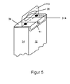
- Figure 5 discloses the fully assembled and closed folding box 1 4 in the area of the upper closure 30, before the first Open the folding box 1.
- FIG. 6 the completely assembled and closed folding box 1 according to FIG. 4 is shown in the area of the upper closure 30 in a slightly modified form, specifically a roof pitch is wanted in the area of the upper closure 30 in order to increase the attractiveness of the folding box 1.
- the two cover sections 3111 and 3112 are designed in such a way that the sum of the widths of the two cover sections 3111 and 3112 extends far beyond the width of the two bottom closure tabs 21, 22.
- the flat, unglued die cut is an alternative executed folding box 1 shown in the area of the upper closure 30 with is provided with a hanger.
- the closing flap 31 is composed of the lid section 311, the first Suspension bracket 312 with a suspension device 35, the second suspension bracket 313 with a suspension device 36 and the tab 314.
- the second suspension bracket 313 with a suspension device 36 and the bracket 314 are combined into a single wall.
- FIG. 8 which shows the fully assembled and closed folding box 1 7 shows in the area of the upper closure 30, before the first opening, can be removed, is achieved through this type of Formation of the locking tab 31 that the hanger in the extension of the rear side wall 12 is located.
- FIG. 9 shows in a lateral section how the hanger according to FIG. 8 composed.
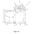
- the flat, unglued punch blank is another alternatively designed folding box 1 shown in the area of the upper closure 30 is provided with a hanger.
- the locking tab 31 is composed of the first hanging tab 312 with a hanging device 35, the second hanging tab 313 with a hanging device 36, the cover section 311 and the tab 314.
- the first suspension bracket 312 with a suspension device 35 and the rear side wall 12 are combined into a single wall.
- FIG. 11 which shows the fully assembled and closed folding box 1 10 shows in the area of the upper closure 30, before the first opening, can be removed, is achieved through this type of Formation of the locking tab 31 that the hanger in the extension of the front side wall 11 is located.
- FIG. 12 finally shows in a lateral section how the hanger according to FIG. 11 composed.
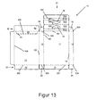
- the flat, unglued die cut is an alternative executed folding box 1 shown in the area of the upper closure 30 with is provided with a hanger.
- the flap 31 is articulated on the front side wall 11 via a fold line 301, as is known from FIG.
- the closing flap 31 is composed of a first section 3111 of the cover section 311, which is articulated on the front side wall 11 via a fold line 301, a first hanging tab 312 with a suspension device 35, which is articulated on the first section 3111 via a fold line 305, one second hanging tab 313 with a hanging device 36, which is articulated on the first hanging tab 312 via a fold line 306, a second cover section 3112, which is articulated on the second hanging tab 313 via a fold line 307, the tab 314, which is connected to the second via the fold line 302 Lid portion 3112 is hinged.
- the sum of the widths of the two lid sections 3111 and 3112 corresponds approximately to the width of the two bottom closure tabs 21, 22. In the preferred embodiment of the folding box 1 shown here, the two lid sections 3111 and 3112 are of equal width.
- a further closure flap 42 is located on the tear-open flap 40 via a fold line 401 articulated, which is located in the extension of the rear side wall 11.
- the Sealing flap has approximately the same dimensions as that Floor locking tabs 21, 22.
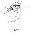
- FIG. 14 shows how the folding box 1 is assembled.
- the locking tab 42 is folded down by 90 °, placed on the flaps 33, 34 and with them bonded.
- the process of assembling the folding box 1 according to FIG. 4 takes place, in order to erect the folding box 1 first at the upper closure 30 the narrower side walls 13, 14 located locking tabs 33, 34 to the inside be folded. Then the flap 31 is converted into the desired shape, by folding the hanging tabs 312, 313 so that the two Suspension brackets 312, 313 lie one above the other so that they can be glued, so that the hanger of the folding box 1 extremely through the double material wall is stable.
- the two cover sections 3111 and 3112 are aligned in parallel.
- the tab 314 is glued to the tear tab 40.
- the upper closure 30 and the bottom closure 20 of the folding box 1 are not Can be opened without using force and therefore theft-proof and dust-protected.
Landscapes
- Engineering & Computer Science (AREA)
- Mechanical Engineering (AREA)
- Cartons (AREA)
Abstract
Description
Nach der Befüllung dieser Faltschachtel mit dem zu verkaufenden Gut muß sie in einer möglichst bequem handhabbaren und ansprechender Weise dem Kunden dargeboten werden. Eine sehr übersichtliche Methode des Angebots ist mittels der allgemein bekannten Selbstbedienungshaken in Verkaufsregalen möglich, die die Aufnahme mehrerer, hintereinander angeordneter Faltschachteln erlauben.
Damit die beschriebene Faltschachtel an einem solchen Haken aufgehängt werden kann, muß zusätzlich ein entsprechend ausgeformter Zuschnitt mit einer Aufhängevorrichtung an der Faltschachtel angebracht werden. Zumeist erfolgt dies, indem dies Teil mit der entsprechenden Aufhängevorrichtung an der Faltschachtel an geeigneter Stelle in einem zusätzlichem Arbeitsgang angeklebt wird. Somit wird aber der Herstellungsprozeß der Faltschachtel u.a. durch das Herstellen des weiteren Zuschnitts oder das Ankleben desselben an der fertigen Schachtel verkompliziert und durch mehrere Arbeitsschritte zeitlich verlängert, darüber hinaus bedeutet dies einen sehr viel höheren apparativen Aufwand.
Mit Hilfe der Aufhängelasche ist eine Plazierung der Faltschachtel an einem Haken möglich. Da die Aufhängelasche aber lediglich einlagig ausgeführt ist und aus dem gleichen Material wie die übrige Faltschachtel besteht, treten im praktischen Gebrauch der Faltschachtel Probleme auf.
Ist die Faltschachtel unter Berücksichtigung von Umwelt- und Kostenaspekten aus dünnem Material gefertigt, weist die Aufhängelasche ein unzureichende Stabilität auf. Schon bei leichtem, unbeabsichtigtem Ziehen an der Faltschachtel reißt die Aufhängelasche aus, so daß die Aufhängelasche ihre Funktion verliert und die Schachtel nicht mehr wie gewünscht aufgehängt werden kann. Darüber hinaus wird die Schachtel unansehnlich und kann damit nicht mehr dem Kunden dargeboten werden.
Diese Schachtel zeigt aber bei ihrer Herstellung und Verwendung einige Nachteile.
Der Zuschnitt der in der amerikanischen Patentschrift offenbarten Schachtel besitzt einen senkrechten Aufbau, d.h., die beiden Aufhängelaschen sowie die Endlasche, die alle zusammen den Aufhänger der Schachtel bilden, sind in einer geraden Linie mit den vier Seitenwänden angeordnet, wobei die einzelnen Teile jeweils mit einer Falzlinie miteinander verbunden sind. Diese Art des Faltzuschnitts bedingt, daß nach der Konfektionierung des Korpus der Schachtel eine Befüllung derselben nur noch seitlich möglich ist und nicht, wie allgemein üblich und erwünscht, von oben. Dies bedingt den Einsatz von speziell auf diesen Zuschnitt ausgerichteter, ansonsten eher unüblicher Kartonier- und Befüllungsmaschinen.
Weiterhin ergibt sich bei der fertig konfektionierten Schachtel im Bereich des Aufhängers ein Abschnitt, der eine dreifache Materialstärke durch drei übereinander liegende Wände aufweist und somit überdimensioniert ist, was die Schachtel in der Herstellung durch einen erhöhten Materialverbrauch verteuert, und was gleichzeitig zu einem erhöhten Gewicht der Schachtel mit den allseits bekannten Nachteilen führt.
Die Öffnung der Schachtel ist nur möglich, indem zunächst ein Streifen Material über der eigentlichen Öffnung irreversibel entfernt wird und dieser somit als aus heutigen umweltschutzrechtlichen Gesichtspunkten unerwünschter Abfall endet. Anschließend wird die Schachtel an einer Perforationslinie aufgebrochen.
Das Wiederverschließen der Schachtel kann nur dadurch erfolgen, daß der Aufhänger nach entsprechender Faltung gleichzeitig als Verschlußdeckel dient und in die Öffnung der Schachtel geschoben wird. Somit ist ausgeschlossen, daß die Schachtel nach erstmaliger Öffnung und darauffolgendem Verschließen wieder an ihrem eigentlichen Aufhänger aufgehängt werden kann. Der Aufhänger verliert damit seine ursprüngliche und eigentliche Funktion.
Und schließlich bedingt die gleichzeitige Verwendung des Aufhängers als Verschlußdeckel für die Schachtel, daß bei noch versiegelter Schachtel, insbesondere wenn die Schachtel eine große bauliche Tiefe aufweist, ein großer, sperriger Aufhänger entsteht, der beispielsweise dazu führt, daß die Schachtel beim Aufhängen in einem Regal sehr viel Grundfläche beansprucht, so daß die eigentliche Kapazität des Regals mit den offenbarten Schachteln nur ungenügend ausgenutzt werden kann.
An die rückwärtige Seitenwand ist in ihrem aufreißlaschenfreien Bereich eine in der von der rückwärtigen Seitenwand gebildeten Ebene liegende erste Aufhängelasche mit einer Aufhängevorrichtung, wie Schlitz- oder Rundlochung, angelenkt. Gleichzeitig ist aus dem gleichen Bereich der Innenrückwand wie bei der rückwärtigen Seitenwand und ausgehend von der Falzlinie zwischen Innenrückwand und Verschlußlappen eine zweite Aufhängelasche mit einer Aufhängevorrichtung, wie Schlitz- oder Rundlochung, ausgestanzt, wobei der an der Innenrückwand angelenkte Verschlußlappen an der Falzlinie eine größere Breite aufweist als die zweite Aufhängelasche.
Der vierte Verschlußlappen setzt sich erfindungsgemäß aus mehreren Abschnitten zusammen, und zwar im einzelnen aus
- einer ersten Aufhängelasche mit einer Aufhängevorrichtung, die über eine Falzlinie an der rückwärtigen Seitenwand der Faltschachtel angelenkt ist, wobei an der ersten Aufhängelasche über eine Falzlinie
- eine zweite Aufhängelasche mit einer Aufhängevorrichtung angelenkt ist, wobei an der zweiten Aufhängelasche über eine Falzlinie
- eine Endlasche angelenkt ist,
- wobei die erste Aufhängelasche, die zweite Aufhängelasche und die Endlasche geradlinig hintereinander angeordnet sind, wobei die drei weiteren Verschlußlappen sowie der vierte Verschlußlappen jeweils an der selben Seite der vier Seitenwände angelenkt sind und wobei bei der fertig konfektionierten Faltschachtel die Endlasche mit dem an der vorderen Seitenwand angelenkten Verschlußlappen verklebt ist.
Der etwas erfahrenere Kunde öffnet die Faltschachtel wie vorgesehen am Originalitätsverschluß, entnimmt das gewünschte Produkt, zum Beispiel ein Pflaster, und verschließt die Schachtel danach wieder. Hängt man diese nun an dem Aufhänger an einen Haken, befindet sich der geschlossene Verschluß unten. Es ist daher nicht auszuschließen, daß die Faltschachtel unbeabsichtigt aufgeht und die darin befindlichen Produkte herausfallen.
Diese Wand hat einen komplizierteren Zuschnitt zur Folge mit größerem Abfall, des weiteren erhöht diese Wand die Materialkosten. Schließlich erhöht die Wand das zu entsorgende Gewicht der Faltschachtel.
Ebenso kann die Falzlinie zwischen der ersten Aufhängelasche und der zweiten Aufhängelasche mit messerschnittartigen Durchstanzungen versehen sein.
Die Aufreißlasche ist somit nach dem erstmaligen Aufbrechen der Faltschachtel unterhalb des Deckelabschnitts nicht zu sehen, so daß der optische Eindruck der Faltschachtel nicht getrübt ist. Des weiteren hat diese Ausführungsform den Vorteil, daß die nach dem Entfernen der Aufreißlasche in der rückwärtigen Seitenwand vorhandene Lücke komplett vom Deckelabschnitt geschlossen wird, wenn dieser zum Verschließen der Faltschachtel unter die rückwärtige Seitenwand geführt wird.
Die Faltschachtel weist unter der sichtbaren Lasche einen Originalitätsverschluß auf. Dieser Originalitätsverschluß wird dadurch geschaffen, daß die Fläche der Unterseite des Deckelabschnitts eine durch Verklebung geschaffene Einheit mit der perforierten Aufreißlasche auf dem Korpus der Faltschachtel bildet. Diese perforierte Aufreißlasche liegt unterhalb der draufliegenden, verklebten Einstecklasche und ist so perforiert, daß sich diese beim Erstöffnen der Faltschachtel durch ein leichtes Eindrücken der beiden miteinander verklebten übereinander liegenden Flächen vom Korpus der Faltschachtel trennen. Das Wiederverschließen der Faltschachtel kann, wie bekannt, durch das Wiedereinstecken des Deckelabschnitts erfolgen. Nach dem Öffnen der Faltschachtel kann das Produkt entnommen werden.
Beim späteren Verkleben der Faltschachtel erhöht sich auf diese Weise die Stabilität derselben.
Die Verschlußlasche wird um 90° umgeklappt, auf die Verschlußlappen gelegt und mit diesen verklebt. Auf diese Weise erhöht sich die Drucksteifigkeit der Faltschachtel derart, daß ein Einsinken des oberen Verschlusses der Faltschachtel ausgeschlossen werden kann.
Die Faltschachtel ist maschinengängig; sie wird als flachliegender Zuschnitt geklebt, vom Kartonierer aufgerichtet und zur Befüllstation transportiert, wobei die Aufhängelasche bereits an der Faltschachtel mit ausgebildet ist. Vorder- und Rückseite der Faltschachtel bieten hervorragende Gestaltungsmöglichkeiten. Nach dem Aufrichten und Befüllen der Faltschachtel ist eine einfache Verklebung des Kopfbereiches und des mittigen Bereiches möglich. Durch diese Verklebung wird ein guter Staubschutz erhalten, so daß ein nachträglicher Volleinschlag oder eine zusätzliche Verpackung der Faltschachtel entfällt.
Bis auf den Aufhänger sind bei der Faltschachtel ansonsten die Wände, mit Ausnahme von vorgesehenen Verklebungsstellen, jeweils einlagig ausgeführt. Auf diese Weise wird insgesamt sehr wenig Material für die Gestaltung der Faltschachtel verbraucht, und dennoch ein belastbarer Aufhänger gebildet.
- Figur 1
- den flachliegenden, ungeklebten Stanzzuschnitt der besonders vorteilhaft ausgeführten Faltschachtel,
- Figur 2 und Figur 3
- die vollständig konfektionierte und geschlossene Faltschachtel im Bereich des oberen Verschlusses, und zwar zum einen vor dem erstmaligen Öffnen und zum anderen nach dem erstmaligen Öffnen,
- Figur 4
- den flachliegenden, ungeklebten Stanzzuschnitt einer alternativ ausgeführten Faltschachtel,
- Figur 5
- die vollständig konfektionierte und geschlossene Faltschachtel gemäß Figur 4 im Bereich des oberen Verschlusses, und zwar vor dem erstmaligen Öffnen,
- Figur 6
- die vollständig konfektionierte und geschlossene Faltschachtel gemäß Figur 4 im Bereich des oberen Verschlusses in leicht veränderter Form,
- Figur 7
- den flachliegenden, ungeklebten Stanzzuschnitt einer weiteren alternativ ausgeführten Faltschachtel,
- Figur 8
- die vollständig konfektionierte und geschlossene Faltschachtel gemäß Figur 7 im Bereich des oberen Verschlusses, und zwar vor dem erstmaligen Öffnen,
- Figur 9
- den Aufhänger der Faltschachtel gemäß Figur 8 im seitlichen Schnitt,
- Figur 10
- den flachliegenden, ungeklebten Stanzzuschnitt einer weiteren alternativ ausgeführten Faltschachtel,
- Figur 11
- die vollständig konfektionierte und geschlossene Faltschachtel gemäß Figur 10 im Bereich des oberen Verschlusses, und zwar vor dem erstmaligen Öffnen,
- Figur 12
- den Aufhänger der Faltschachtel gemäß Figur 11 im seitlichen Schnitt,
- Figur 13
- den flachliegenden, ungeklebten Stanzzuschnitt einer weiteren alternativ ausgeführten Faltschachtel,
- Figur 14
- die vollständig konfektionierte und geschlossene Faltschachtel gemäß Figur 13 im Bereich des oberen Verschlusses, und zwar vor dem erstmaligen Öffnen.
Die zur Öffnung der Faltschachtel 1 vorgesehene Aufreißlasche 40 ist vermittels einer Schwächungs- oder Sollbruchlinie 41 in der rückwärtigen Seitenwand 12 gehalten, und zwar im Bereich des oberen Verschlusses 30.
An die rückwärtige Seitenwand 12 ist eine Lasche 16 angelenkt, wobei zum unlösbaren Verschließen des Korpus die Lasche 16 mit der linken Seitenwand 14 verklebt werden kann.
An den beiden schmalen Seitenwänden 13, 14 sind zwei weitere Bodenverschlußlappen 23, 24 über die Falzlinien 203, 204 angelenkt, die sich zu ihrem freien Ende hin verjüngen und die eine im wesentlichen trapezförmige Gestaltung aufweisen.
Die beiden Verschlußlappen 33, 34 besitzen vorzugsweise die gleiche Form und Abmessung wie die beiden Bodenverschlußlappen 23, 24.
An den beiden schmalen Seitenwänden 13, 14 sind zwei weitere Verschlußlappen 33, 34 über die Falzlinien 303, 304 angelenkt, die sich zu ihrem freien Ende hin verjüngen und die eine im wesentlichen trapezförmige Gestaltung aufweisen.
Die Lasche 314, die an dem Deckelabschnitt 311 angelenkt ist, erstreckt sich über die gesamte Breite der vorderen Seitenwand 11. Die Lasche 314 deckt die Aufrißlasche 40 flächenmäßig vollständig ab, so daß die Aufreißlasche 40 unterhalb der Lasche 314 liegt und dort von außen nicht zu sehen ist.
Die Faltschachtel 1 ist somit nicht zu öffnen, ohne daß diese beschädigt wird.
Die Summe der Breiten der beiden Deckelabschnitte 3111 und 3112 entspricht ungefähr der Breite der beiden Bodenverschlußlappen 21, 22. Bei der hier dargestellten bevorzugten Ausführungsform der Faltschachtel 1 sind die beiden Deckelabschnitte 3111 und 3112 gleich breit.
An die erste Aufhängelasche 312 ist die zweite Aufhängelasche 313 angelenkt, die die gleiche Form und Abmessung wie die erste Aufhängelasche 312 aufweist, lediglich die Aufhängevorrichtung 36 ist etwas kleiner als die Aufhängevorrichtung 35 der ersten Aufhängelasche 312, ist aber in Relation zur ersten Aufhängelasche 312 in einem Winkel von 180° gedreht, so daß beim Umknicken der zweiten Aufhängelasche 313 über die Falzlinie 306 die beiden Aufhängelaschen 312, 313 derartig übereinander liegen, daß die beiden Aufhängevorrichtungen 35, 36 möglichst deckungsgleich angeordnet sind. Vorteilhafterweise können die beiden Aufhängelaschen 312, 313 miteinander verklebt sein, was die Stabilität erhöht.
Diese Verklebung wird mit dem Erstöffnen der Faltschachtel 1 gelöst, so daß eine Beeinträchtigung durch die Verklebung beim Erstverschließen ausgeschlossen werden kann.
Dazu werden die beiden Deckelabschnitte 3111 und 3112 derartig ausgeführt, daß die Summe der Breiten der beiden Deckelabschnitte 3111 und 3112 weit über die Breite der beiden Bodenverschlußlappen 21, 22 hinausgeht.
Die erste Aufhängelasche 312 mit einer Aufhängevorrichtung 35 sowie die rückwärtige Seitenwand 12 sind zu einer einzigen Wand zusammengefaßt.
Die Summe der Breiten der beiden Deckelabschnitte 3111 und 3112 entspricht ungefähr der Breite der beiden Bodenverschlußlappeh 21, 22. Bei der hier dargestellten bevorzugten Ausführungsform der Faltschachtel 1 sind die beiden Deckelabschnitte 3111 und 3112 gleich breit.
Claims (11)
- Wiederverschließbare, quaderförmige Faltschachtel 1 mit einer vorderen Seitenwand 11, einer rückwärtigen Seitenwand 12, einer die vordere Seitenwand 11 und die rückwärtige Seitenwand 12 verbindenden, rechten Seitenwand 13 sowie einer linken Seitenwand 14, einem von insbesondere vier Bodenverschlußlappen 21, 22, 23, 24 gebildeten Bodenverschluß 20, einem oberen Verschluß 30, wobei zwei Bodenverschlußlappen 21, 22 miteinander verklebt sein können, mit einer in der rückwärtigen Seitenwand 12 integrierten Aufreißlasche 40, die vermittels einer Schwächungs- oder Sollbruchlinie 41 in der rückwärtigen Seitenwand 12 gehalten ist,
wobei an der vorderen Seitenwand 11 ein oberer Verschlußlappen 31 angelenkt ist, bestehend ausa) einem Deckelabschnitt 311, der über eine Falzlinie 301 an der vorderen Seitenwand 11 angelenkt ist,b) einer Lasche 314, die über eine Falzlinie 302 an dem Deckelabschnitt 311 angelenkt ist,c) wobei die Lasche 314 bei konfektionierter Faltschachtel 1 die Aufreißlasche 40 in der rückwärtigen Seitenwand 12 außenwärts übergreift und auf der Aufreißlasche 40 verklebt ist. - Wiederverschließbare, quaderförmige Faltschachtel gemäß Anspruch 1, dadurch gekennzeichnet, daß im oberen Verschlußlappen 31 eine erste Aufhängelasche 312 mit einer Aufhängevorrichtung 35 sowie eine zweite Aufhängelasche 313 mit einer Aufhängevorrichtung 36 vorhanden sind, die insbesondere über eine Falzlinie 306 miteinander verbunden sind.
- Wiederverschließbare, quaderförmige Faltschachtel gemäß Anspruch 2, dadurch gekennzeichnet, daß die Aufhängelaschen 312, 313 zwischen der vorderen Seitenwand 11 und dem Deckelabschnitt 311 angeordnet sind.
- Wiederverschließbare, quaderförmige Faltschachtel gemäß Anspruch 2, dadurch gekennzeichnet, daß die Aufhängelaschen 312, 313 zwischen dem Deckelabschnitt 311 und der Lasche 314 angeordnet sind.
- Wiederverschließbare, quaderförmige Faltschachtel gemäß Anspruch 2, dadurch gekennzeichnet, daß die Aufhängelaschen 312, 313 den Deckelabschnitt 311 bevorzugt mittig teilen.
- Wiederverschließbare, quaderförmige Faltschachtel gemäß zumindest einem der vorherigen Ansprüche, dadurch gekennzeichnet, daß die Aufhängevorrichtung 35 in der ersten Aufhängelasche 312 größer ist als die Aufhängevorrichtung 36 in der zweiten Aufhängelasche 313.
- Wiederverschließbare, quaderförmige Faltschachtel gemäß zumindest einem der vorherigen Ansprüche, dadurch gekennzeichnet, daß bei der fertig konfektionierten Faltschachtel 1 die erste Aufhängelasche 312 und die zweite Aufhängelasche 313 miteinander verklebt sind.
- Wiederverschließbare, quaderförmige Faltschachtel gemäß zumindest einem der vorherigen Ansprüche, dadurch gekennzeichnet, daß an der Aufreißlasche 40 über eine Falzlinie 401 eine weitere Verschlußlasche 32 angelenkt ist.
- Wiederverschließbare, quaderförmige Faltschachtel gemäß zumindest einem der vorherigen Ansprüche, dadurch gekennzeichnet, daß die Lasche 314 die Aufreißlasche 40 flächenmäßig vollständig abdeckt.
- Wiederverschließbare, quaderförmige Faltschachtel gemäß zumindest einem der vorherigen Ansprüche, enthaltend zumindest einen flachen Gegenstand, insbesondere ein oder mehrere Pflaster.
- Stanzzuschnitt zur Herstellung einer wiederverschließbaren, quaderförmigen Faltschachtel 1 mit einer vorderen Seitenwand 11, einer rückwärtigen Seitenwand 12, einer die vordere Seitenwand 11 und die rückwärtige Seitenwand 12 verbindenden, rechten Seitenwand 13 sowie einer linken Seitenwand 14, einem von vier Bodenverschlußlappen 21, 22, 23, 24 gebildeten Bodenverschluß 20, einem von drei Verschlußlappen 31, 33, 34 gebildeten oberen Verschluß 30, wobei zwei Bodenverschlußlappen 21, 22 miteinander verklebt sein können, mit einer in der rückwärtigen Seitenwand 12 integrierten Aufreißlasche 40, die vermittels einer Schwächungs- oder Sollbruchlinie 41 in der rückwärtigen Seitenwand 12 gehalten ist und die gegebenenfalls über eine Falzlinie 401 mit einem Verschlußlappen 32 des oberen Verschlusses 30 verbunden ist, sowie mit Lasche 16,
wobei
die Faltschachtel 1 aus einem Faltzuschnitt 10 aus Pappe, Karton oder einem anderen geeigneten Werkstoff besteht,
wobei die rückwärtige Seitenwand 12, die die vordere Seitenwand 11 und die rückwärtige Seitenwand 12 verbindende, rechte Seitenwand 13, die vordere Seitenwand 11, die linke Seitenwand 14, die Lasche 16 jeweils über Falzlinien 101, 102, 103, 104 miteinander verknüpft in einer Reihe geradlinig hintereinander angeordnet sind,
wobei an der die vordere Seitenwand 11 und die rückwärtige Seitenwand 12 verbindenden, rechten Seitenwand 13 zum einen über eine Falzlinie 303 ein Verschlußlappen 33 und zum anderen auf der gegenüberliegenden Seite über eine Falzlinie 203 ein Bodenverschlußlappen 23 angelenkt ist,
wobei an der vorderen Seitenwand 11 zum einen über eine Falzlinie 301 ein Verschlußlappen 31 und zum anderen auf der gegenüberliegenden Seite über eine Falzlinie 201 ein Bodenverschlußlappen 21 angelenkt ist, wobei der obere Verschlußlappen 31 besteht auswobei an der linken Seitenwand 14 zum einen über eine Falzlinie 304 ein Verschlußlappen 34 und zum anderen auf der gegenüberliegenden Seite über eine Falzlinie 204 ein Bodenverschlußlappen 24 angelenkt ist,a) einem Deckelabschnitt 311, der über eine Falzlinie 301 an der vorderen Seitenwand 11 angelenkt ist,b) einer Lasche 314, die über eine Falzlinie 302 an dem Deckelabschnitt 311 angelenkt ist,c) wobei die Lasche 314 bei konfektionierter Faltschachtel 1 die Aufreißlasche 40 in der rückwärtigen Seitenwand 12 außenwärts übergreift und auf der Aufreißlasche 40 verklebt ist,
wobei in der rückwärtigen Seitenwand 12 eine Aufreißlasche 40, die vermittels einer Schwächungs- oder Sollbruchlinie 41 in der rückwärtigen Seitenwand 12 gehalten ist und die gegebenenfalls über eine Falzlinie 401 mit einem Verschlußlappen 32 des oberen Verschlusses 30 verbunden ist.
Applications Claiming Priority (2)
| Application Number | Priority Date | Filing Date | Title |
|---|---|---|---|
| DE10061402A DE10061402A1 (de) | 2000-12-09 | 2000-12-09 | Wiederverschließbare, quaderförmige Faltschachtel |
| DE10061402 | 2000-12-09 |
Publications (2)
| Publication Number | Publication Date |
|---|---|
| EP1213226A2 true EP1213226A2 (de) | 2002-06-12 |
| EP1213226A3 EP1213226A3 (de) | 2002-06-19 |
Family
ID=7666501
Family Applications (1)
| Application Number | Title | Priority Date | Filing Date |
|---|---|---|---|
| EP01126177A Withdrawn EP1213226A3 (de) | 2000-12-09 | 2001-11-05 | Wiederverschliessbare, quaderförmige Faltschachtel |
Country Status (4)
| Country | Link |
|---|---|
| US (1) | US20020070268A1 (de) |
| EP (1) | EP1213226A3 (de) |
| AU (1) | AU9511901A (de) |
| DE (1) | DE10061402A1 (de) |
Families Citing this family (17)
| Publication number | Priority date | Publication date | Assignee | Title |
|---|---|---|---|---|
| DE10239711A1 (de) | 2002-08-29 | 2004-03-11 | Beiersdorf Ag | Wiederverschließbare, quaderförmige Faltschachtel mit Aufbrechsicherheitsverschluss und Aufhängelasche |
| DE10300752A1 (de) * | 2002-11-12 | 2004-05-27 | Henkel Kgaa | Verpackung für schüttfähige Güter aus einem Faltzuschnitt |
| US20040256273A1 (en) * | 2002-11-13 | 2004-12-23 | Beiersdorf Ag | Relockable, rectangular-shaped folding box with lateral opening |
| DE10252683A1 (de) * | 2002-11-13 | 2004-06-03 | Beiersdorf Ag | Wiederverschließbare, quaderförmige Faltschachtel mit seitlicher Öffnung und Aufhängelasche |
| US20040222281A1 (en) * | 2003-05-09 | 2004-11-11 | Thomas Mangerson | Mailing product and method |
| WO2005000692A1 (de) * | 2003-06-23 | 2005-01-06 | Beiersdorf Ag | Wiederverschliessbare, quaderförmige faltschachtel mit seitlicher wieder verschliessbarer öffnung |
| US20060091190A1 (en) * | 2004-10-28 | 2006-05-04 | Dave Nikolai | Carton with multiple closure formations |
| US8061585B2 (en) * | 2007-01-30 | 2011-11-22 | Graphic Packaging International, Inc. | Reclosable cartons |
| US20080290149A1 (en) * | 2007-05-24 | 2008-11-27 | Graphic Packaging International, Inc. | Cartons and methods of erecting cartons |
| JP5164578B2 (ja) * | 2008-01-04 | 2013-03-21 | ナカバヤシ株式会社 | 包装箱 |
| US20100270367A1 (en) * | 2009-04-28 | 2010-10-28 | Brandenburger Allen M | Carton with display panel |
| USD620354S1 (en) | 2009-07-21 | 2010-07-27 | The C.W. Zumbiel Company | Carton with handle |
| US20120006818A1 (en) * | 2010-07-08 | 2012-01-12 | Tom Fester | Corrugated Barrier Cartonboard |
| US20130020382A1 (en) * | 2011-07-18 | 2013-01-24 | Meadwestvaco Corporation | Paperboard accordion package |
| WO2019018265A1 (en) | 2017-07-17 | 2019-01-24 | Graphic Packaging International, Llc | CARTON COMPRISING LOCKING ELEMENTS |
| USD845760S1 (en) | 2017-07-17 | 2019-04-16 | Graphic Packaging International, Llc | Carton |
| JP7327780B2 (ja) * | 2019-05-28 | 2023-08-16 | 小倉美術印刷株式会社 | 包装箱 |
Citations (5)
| Publication number | Priority date | Publication date | Assignee | Title |
|---|---|---|---|---|
| US4344533A (en) | 1980-07-28 | 1982-08-17 | Grinnell Lithographic Co., Inc. | Fifth panel reclosable package |
| DE3932441A1 (de) | 1989-09-28 | 1991-04-11 | Beiersdorf Ag | Wiederverschliessbare, quaderfoermige faltschachtel |
| DE4322555A1 (de) | 1993-07-07 | 1995-01-12 | Beiersdorf Ag | Wiederverschließbare, quaderförmige Faltschachtel und Faltzuschnitt zu deren Herstellung |
| DE19535008A1 (de) | 1995-09-21 | 1997-03-27 | Beiersdorf Ag | Faltschachtel mit verstärktem Aufhänger |
| DE19541904A1 (de) | 1995-11-10 | 1997-05-15 | Beiersdorf Ag | Faltschachtel mit integrierter Doppellasche |
Family Cites Families (9)
| Publication number | Priority date | Publication date | Assignee | Title |
|---|---|---|---|---|
| FR767628A (de) * | 1934-01-16 | 1934-07-20 | ||
| GB1445156A (en) * | 1973-09-04 | 1976-08-04 | Metal Box Co Ltd | Display cartons |
| US3893614A (en) * | 1973-11-23 | 1975-07-08 | American Can Co | Tamperproof reclosable carton |
| US4062486A (en) * | 1976-11-04 | 1977-12-13 | The Procter & Gamble Company | Carton |
| US4291807A (en) * | 1979-11-07 | 1981-09-29 | International Folding Paper Box Co., Inc. | Folding box |
| DE8909650U1 (de) * | 1989-02-15 | 1989-11-02 | Johnson & Johnson Gesellschaft m.b.H., Hallein | Faltkarton |
| DE19637022B4 (de) * | 1996-09-12 | 2007-06-06 | Beiersdorf Ag | Handfaltschachtel mit Sicherheitsverschluß |
| DE19735003A1 (de) * | 1997-08-13 | 1999-02-18 | Beiersdorf Ag | Faltschachtel mit Originalitätsverschluß |
| DE19848719A1 (de) * | 1998-10-22 | 2000-05-04 | Beiersdorf Ag | Wiederverschließbare, quaderförmige Faltschachtel mit Aufhänger |
-
2000
- 2000-12-09 DE DE10061402A patent/DE10061402A1/de not_active Withdrawn
-
2001
- 2001-11-05 EP EP01126177A patent/EP1213226A3/de not_active Withdrawn
- 2001-11-20 US US09/988,547 patent/US20020070268A1/en not_active Abandoned
- 2001-11-28 AU AU95119/01A patent/AU9511901A/en not_active Abandoned
Patent Citations (5)
| Publication number | Priority date | Publication date | Assignee | Title |
|---|---|---|---|---|
| US4344533A (en) | 1980-07-28 | 1982-08-17 | Grinnell Lithographic Co., Inc. | Fifth panel reclosable package |
| DE3932441A1 (de) | 1989-09-28 | 1991-04-11 | Beiersdorf Ag | Wiederverschliessbare, quaderfoermige faltschachtel |
| DE4322555A1 (de) | 1993-07-07 | 1995-01-12 | Beiersdorf Ag | Wiederverschließbare, quaderförmige Faltschachtel und Faltzuschnitt zu deren Herstellung |
| DE19535008A1 (de) | 1995-09-21 | 1997-03-27 | Beiersdorf Ag | Faltschachtel mit verstärktem Aufhänger |
| DE19541904A1 (de) | 1995-11-10 | 1997-05-15 | Beiersdorf Ag | Faltschachtel mit integrierter Doppellasche |
Also Published As
| Publication number | Publication date |
|---|---|
| DE10061402A1 (de) | 2002-06-13 |
| EP1213226A3 (de) | 2002-06-19 |
| US20020070268A1 (en) | 2002-06-13 |
| AU9511901A (en) | 2002-06-13 |
Similar Documents
| Publication | Publication Date | Title |
|---|---|---|
| EP0995689B1 (de) | Wiederverschliessbare, quaderförmige Faltschachtel mit Aufhänger | |
| DE69324146T2 (de) | Klappschachtel mit herausspringendem gutschein | |
| DE10301481B4 (de) | Prismenförmiges Gebinde | |
| EP1213226A2 (de) | Wiederverschliessbare, quaderförmige Faltschachtel | |
| EP1394054B1 (de) | Wiederverschliessbare Faltschachtel mit Aufbrechsicherheitsverschluss und Aufhängelasche und Stanzzuschnitt zu ihrer Herstellung | |
| DE4322555C2 (de) | Wiederverschließbare, quaderförmige Faltschachtel und Faltzuschnitt zu deren Herstellung | |
| EP3439979B1 (de) | Wiederverschliessbare faltschachtel mit originalitätsverschluss und faltschachtelzuschnitt zu ihrer herstellung | |
| DE19541904B4 (de) | Faltschachtel mit integrierter Doppellasche | |
| EP1876103A1 (de) | Originalitätsverschlossene Faltschachtel mit schachteleinwärts versetztem Deckel | |
| DE19637022A1 (de) | Handfaltschachtel mit Sicherheitsverschluß | |
| EP1127796B1 (de) | Wiederverschliessbare, quaderförmige Faltschachtel mit Aufhänger | |
| EP0419781B1 (de) | Wiederverschliessbare, quaderförmige Faltschachtel und Faltzuschnitt zu deren Herstellung | |
| EP1195329A2 (de) | Faltschachtel mit schachteleinwärts versetztem Innenboden | |
| DE10015053A1 (de) | Faltschachtel mit integrierter Klappe und Orginalitätsverschluß | |
| DE19535008A1 (de) | Faltschachtel mit verstärktem Aufhänger | |
| EP1638850A1 (de) | Wiederverschliessbare, quaderförmige faltschachtel mit seitlicher wieder verschliessbarer öffnung | |
| EP0896928B1 (de) | Faltschachtel mit Originalitätsverschluss | |
| EP1916192B1 (de) | Quaderförmige Faltschachtel mit einem Öffnungsabschnitt | |
| DE19821087B4 (de) | Faltschachtel mit angelenkter, wiederverschließbarer Klappe | |
| DE10355244A1 (de) | Wiederverschließbare, quaderförmige Faltschachtel mit seitlicher wiederverschließbarer Öffnung | |
| DE19730266A1 (de) | Zuschnitt für eine Cigarettenverpackung | |
| EP1419971B1 (de) | Wiederverschliessbare, quaderförmige Faltschachtel mit seitlicher Öffnung | |
| DE19905298B4 (de) | Kartonverpackung mit integralem Klappdeckel | |
| DE10109201C2 (de) | Cigarettenpackung oder Gebindekarton | |
| DE202005006978U1 (de) | Schachtelförmiger Behälter und dessen Zuschnitt |
Legal Events
| Date | Code | Title | Description |
|---|---|---|---|
| PUAI | Public reference made under article 153(3) epc to a published international application that has entered the european phase |
Free format text: ORIGINAL CODE: 0009012 |
|
| PUAL | Search report despatched |
Free format text: ORIGINAL CODE: 0009013 |
|
| AK | Designated contracting states |
Kind code of ref document: A2 Designated state(s): AT BE CH CY DE DK ES FI FR GB GR IE IT LI LU MC NL PT SE TR |
|
| AX | Request for extension of the european patent |
Free format text: AL;LT;LV;MK;RO;SI |
|
| AK | Designated contracting states |
Kind code of ref document: A3 Designated state(s): AT BE CH CY DE DK ES FI FR GB GR IE IT LI LU MC NL PT SE TR |
|
| AX | Request for extension of the european patent |
Free format text: AL;LT;LV;MK;RO;SI |
|
| 17P | Request for examination filed |
Effective date: 20020724 |
|
| 17Q | First examination report despatched |
Effective date: 20021009 |
|
| AKX | Designation fees paid |
Designated state(s): AT BE CH CY DE DK ES FI FR GB GR IE IT LI LU MC NL PT SE TR |
|
| STAA | Information on the status of an ep patent application or granted ep patent |
Free format text: STATUS: THE APPLICATION IS DEEMED TO BE WITHDRAWN |
|
| 18D | Application deemed to be withdrawn |
Effective date: 20030220 |