EP1208993B1 - Eine Wartestation für Drucker mit Ausstossdüsen senkrecht zur Wagenbewegungsrichtung - Google Patents
Eine Wartestation für Drucker mit Ausstossdüsen senkrecht zur Wagenbewegungsrichtung Download PDFInfo
- Publication number
- EP1208993B1 EP1208993B1 EP01120813A EP01120813A EP1208993B1 EP 1208993 B1 EP1208993 B1 EP 1208993B1 EP 01120813 A EP01120813 A EP 01120813A EP 01120813 A EP01120813 A EP 01120813A EP 1208993 B1 EP1208993 B1 EP 1208993B1
- Authority
- EP
- European Patent Office
- Prior art keywords
- carriage
- service station
- feed roller
- inkjet printer
- paper
- Prior art date
- Legal status (The legal status is an assumption and is not a legal conclusion. Google has not performed a legal analysis and makes no representation as to the accuracy of the status listed.)
- Expired - Lifetime
Links
- 230000033001 locomotion Effects 0.000 title description 34
- 238000010304 firing Methods 0.000 title description 12
- 230000005540 biological transmission Effects 0.000 claims description 32
- 230000000712 assembly Effects 0.000 claims 2
- 238000000429 assembly Methods 0.000 claims 2
- 230000008878 coupling Effects 0.000 claims 1
- 238000010168 coupling process Methods 0.000 claims 1
- 238000005859 coupling reaction Methods 0.000 claims 1
- 238000000034 method Methods 0.000 description 7
- 238000004140 cleaning Methods 0.000 description 2
- 239000003086 colorant Substances 0.000 description 2
- 230000002457 bidirectional effect Effects 0.000 description 1
- 229920001577 copolymer Polymers 0.000 description 1
- 238000001035 drying Methods 0.000 description 1
- 230000000694 effects Effects 0.000 description 1
- -1 ethylene, propylene diene Chemical class 0.000 description 1
- 238000002955 isolation Methods 0.000 description 1
- 238000012423 maintenance Methods 0.000 description 1
- 239000002184 metal Substances 0.000 description 1
- 239000004033 plastic Substances 0.000 description 1
- 238000007789 sealing Methods 0.000 description 1
Images


Classifications
-
- B—PERFORMING OPERATIONS; TRANSPORTING
- B41—PRINTING; LINING MACHINES; TYPEWRITERS; STAMPS
- B41J—TYPEWRITERS; SELECTIVE PRINTING MECHANISMS, i.e. MECHANISMS PRINTING OTHERWISE THAN FROM A FORME; CORRECTION OF TYPOGRAPHICAL ERRORS
- B41J23/00—Power drives for actions or mechanisms
- B41J23/02—Mechanical power drives
- B41J23/025—Mechanical power drives using a single or common power source for two or more functions
-
- B—PERFORMING OPERATIONS; TRANSPORTING
- B41—PRINTING; LINING MACHINES; TYPEWRITERS; STAMPS
- B41J—TYPEWRITERS; SELECTIVE PRINTING MECHANISMS, i.e. MECHANISMS PRINTING OTHERWISE THAN FROM A FORME; CORRECTION OF TYPOGRAPHICAL ERRORS
- B41J2/00—Typewriters or selective printing mechanisms characterised by the printing or marking process for which they are designed
- B41J2/005—Typewriters or selective printing mechanisms characterised by the printing or marking process for which they are designed characterised by bringing liquid or particles selectively into contact with a printing material
- B41J2/01—Ink jet
- B41J2/135—Nozzles
- B41J2/165—Prevention or detection of nozzle clogging, e.g. cleaning, capping or moistening for nozzles
- B41J2/16517—Cleaning of print head nozzles
- B41J2/16535—Cleaning of print head nozzles using wiping constructions
- B41J2/16544—Constructions for the positioning of wipers
- B41J2/16547—Constructions for the positioning of wipers the wipers and caps or spittoons being on the same movable support
Definitions
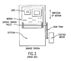
- the service station has a set of "caps" in it, one for each pen-head. During the times when the printer is not in use, the pens are positioned over the service station and the caps are moved to cover the firing heads. This protects the ink in the orifices from drying out during periods of non-nse.
- the capping and wiping functions of the service station require motion in the service station with respect to the pens.
- the squeegee blade may have any topology ranging from short and stiff to long and flexible.
- the squeegee blade is slowly dragged across the pen head, trying to pull some wet ink from each nozzle in an attempt to dissolve dried ink.
- the flicker wipe the blade is rapidly drawn across the orifices to wipe excess ink from the pen. The excess ink on the blade must then be removed. This is typically done by wiping the blade across a fixed plastic section found on the edge of the service station sub-assembly. Because of these different types of operations, speed control of the squeegee is required.
- the paper motor powers the service station.
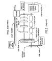
- a carriage motor is connected to a carriage via a gear-set and a belt-drive. The carriage moves along a guided track, propelled by the belt drive.
- the carriage includes one or more pens each containing dedicated firing nozzles.
- a paper path motor provides power to a feed roller via a first gear transmission.
- a paper pick-up transmission lifts the paper into position where a paper pick-up roller pulls the paper into the printer.
- a second gear transmission provides power to the paper pick-up transmission.
- the paper motor is coupled either directly or indirectly to the drive transmission within the service station.
- the carriage motor powers the service station.
- the carriage motor is connected to a carriage via a gear-set and a belt-drive.
- the carriage moves along a guided track, propelled by the belt drive.
- the carriage includes one or more pens each containing dedicated firing nozzles.
- a paper path motor provides power to a feed roller via a first gear transmission.
- a paper pick-up transmission lifts the paper into position where a paper pick-up roller pulls the paper into the printer.
- a second gear transmission provides power to the paper pick-up transmission.
- the axial motion of the carriage is transformed into perpendicular-to-axial motion for the wipers through a number of mechanical means, e.g. levers, gears, springs, or a combination thereof.
- the carriage motion may be used to raise and lower the pen caps also through a series of levers, gears, springs, or a combination thereof.
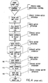
- FIG. 4 illustrates a process flowchart corresponding to the prior art functionality of the printer.
- the printer gains operational control of the job.
- the pens are uncapped and wiped.
- paper is pulled into the printer.
- the carriage is initialized.
- the paper is advanced.
- the carriage is moved and ink is spit onto the paper. Steps 140 and 150 are repeated until the print job is complete. A new piece of paper is loaded without servicing the pens.
- the rest of the flow chart corresponds to when the last page is printed.
- step 160 the paper is "kicked” from the printer, coming to rest in the out tray.
- step 170 the carriage is moved to the "rest" position.
- pens are wiped and capped.
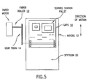
- FIG. 5 illustrates a service station 10 of the present invention.
- Piece 1 would be the wipers 12.
- the wipers 12 must move across the pens in a direction that is parallel to the direction that the paper moves to preserve the ink supply. Through the use of gears 14 connected to the paper rollers 16, the wipers 12 can be made to clean the pens at the same time that the paper is being advanced, using the same motor source.
- Piece 2 is the service station capping function 18. This function requires moving the caps into place as the pens come to rest. The motion of the pens themselves could easily push a lever that pushes the caps into place. A spittoon 20 collects the residual ink.
- the pens come to rest at the right side of the carriage against a lever. This pushes the cap against the pens, sealing them from the atmosphere.
- the pens move to the left of the printer where they wait for the paper to move into position. As they come to rest, they push a toggle that translates the horizontal motion of the carriage to a vertical wiping motion. After the wipe pass is complete, and the pen moves to print, the wiper is returned to its at-rest position, along with the toggle.
- Figure 6 illustrates a process flowchart corresponding to a thermal inkjet printer having a carriage motor that transfers power to the service station.
- the printer gains operational control of the job.
- paper is pulled into the printer.
- the pens are uncapped and wiped.
- the carriage is initialized. Steps 220 and 230 may occur simultaneously.
- the paper is advance.
- the carriage is moved and ink is spit onto the paper. Steps 240 and 250 are repeated until the job is printed.
- step 260 the paper is "kicked” from the printer.
- the pens are wiped and capped.
- the carriage is moved into the "rest" position. Steps 270 and 280 may occur simultaneously.
- Figure 7 illustrates a process flowchart corresponding to a thermal inkjet printer having a paper motor coupled to the service station.
- the printer gains operational control of the job.
- the pens are uncapped and wiped.
- paper is pulled into the printer. Steps 310 and 320 may occur simultaneously.
- the carriage is initialized.
- the paper is advance.
- the carriage is moved and ink is spit onto the paper. Steps 340 and 350 are repeated until the job is printed.
- step 360 the carriage is moved into the "rest" position.
- the pens are wiped and capped.
- the paper is "kicked" from the printer. Steps 370 and 380 may occur simultaneously.
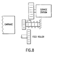
- Figure 8 illustrates one embodiment for the transmission assembly that transfers power from the paper motor to the service station.
- the carriage motor is used as a clutch to engage the gears while movement of the service station comes from the paper motor.
- the carriage pushes an idler into drive and loads the gears.
- the gears transfer power from the feed roller to the service station.
- the paper motor (not shown) powers the feed roller.
- FIG 9 illustrates an alternate embodiment for the transmission assembly.
- the drive gear, idler gear, and link are mounted to the drive shaft.
- the carriage pivots around the carriage slide shaft and tips back toward the service station. This rotation is caused by features in the top sheet metal carriage guide. This "tipping back” engages the idle gear by pushing down on the link when the carriage is over the service station.
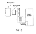
- FIG 10 illustrates another embodiment for the transmission assembly.
- the feed roller runs a bidirectional slip clutch that is tied to the service station gear transmission.
- the service station is driven in the "uncap” direction until it hits the "end of stop”.
- the clutch slips many pages are printed and the pen spits when needed.
- the pen is moved into position over the service station and the feed roller motion is reversed.
- the service station is driven into the "pen cap” position.
- pens are capped as the clutch slips.
- the DC motor may be driven beyond the required distance to ensure that the service station has reached the end of travel.
- Figure 11 illustrates another embodiment for the transmission assembly.
- the carriage motor is coupled to the service station.
- the drive gear does not rotate because it is held by friction and inertia of the service station drive train. It rides on the feed roller shaft (slips). Its teeth are meshed with the service station drive transmission gear.
- the carriage towards the service station it eventually contacts a pressure arm. This arm contacts a rubber ring on the back of the drive gear forcing it against the rubber piece.
- friction between the rubber and the drive gear causes the drive gear to turn, which in turn powers the service station drive train.
- the rubber needs to grip the shaft tightly.
- the angles on the rubber and drive gear can be such that when the gear is pulled tight, it helps the rubber bite into the shaft.
- Figure 12 illustrates another embodiment for the transmission assembly.
- the paper motor is coupled to the service station power by reversing the paper feed roller.
- a one way clutch prevents power from being transferred to the service station drive train.
- the motor is reversed, the one way clutch grabs, engaging the service station drive train.
- the service station pinion drives the rack moving the service station out of pen park (pen cap). The service station continues until it reaches its end of travel at which point the software detects motor stall and the service station is in the spit position.
- a feature on the shuttle activates (shifts) the toggle mechanism to reverse the shuttle drive direction.
- the service station pinion drives the shuttle's rack into the pen cap position. "End of travel” is again reached, the motor stalls, the toggle shifts and the pen is capped.
Landscapes
- Ink Jet (AREA)
- Accessory Devices And Overall Control Thereof (AREA)
Claims (10)
- Ein thermischer Tintenstrahldrucker, der folgende Merkmale aufweist:eine Wagenanordnung, die einen Wagenmotor und Stifte umfasst;eine Papiertransportanordnung, die einen Wagenmotor und eine Zuführrolle umfasst, die mechanisch mit dem Papiermotor gekoppelt ist;eine Wartungsstation (10), die ein Antriebszahnrad aufweist, das mit einem Wischerblatt (12) und einer Stiftabdeckungseinrichtung (18) gekoppelt ist; und gekennzeichnet durch:eine Getriebeanordnung, die die Wagen- und die Papiertransportanordnung mit dem Antriebszahnrad koppelt, wobei die Getriebeanordnung wirksam ist, um Leistung von einer der Wagen- und der Papiertransportanordnung zu dem Wartungsstationsantriebszahnrad zu übertragen.
- Ein thermischer Tintenstrahldrucker gemäß Anspruch 1, bei dem die Leistung von der Wagenanordnung zu der Wartungsstation übertragen wird.
- Ein thermischer Tintenstrahldrucker gemäß Anspruch 2, wobei die Wartungsstation einen mechanischen Auslöser (14) umfasst, der mit dem Wagen gekoppelt ist, wobei der Auslöser die Leistung von der Wagenanordnung zu der Wartungsstation überträgt.
- Ein thermischer Tintenstrahldrucker gemäß Anspruch 3, bei dem der mechanische Auslöser (14) aus einer Gruppe ausgewählt ist, die Zahnräder, Hebel, Federn und Kombinationen derselben umfasst.
- Ein thermischer Tintenstrahldrucker gemäß Anspruch 1, bei dem die Leistung von der Papiertransportanordnung zu der Wartungsstation übertragen wird.
- Ein thermischer Tintenstrahldrucker gemäß Anspruch 5, wobei die Getriebeanordnung ein Leerlaufrad umfasst, das mit der Zuführrolle gekoppelt ist, wobei die Wagenanordnung wirksam ist, um das Leerlaufrad in Eingriff zu nehmen, wobei das Leerlaufrad die Leistung von dem Papiermotor zu dem Antriebszahnrad überträgt.
- Ein thermischer Tintenstrahldrucker gemäß Anspruch 5, bei dem die Getriebeanordnung ferner einen Leerlaufarm umfasst, der ein Leerlaufrad aufweist, wobei die Papiertransportanordnung mit dem Leerlaufarm und dem Leerlaufrad gekoppelt ist, wobei das Leerlaufrad die Leistung von dem Papiermotor zu dem Antriebszahnrad überträgt.
- Ein thermischer Tintenstrahldrucker gemäß Anspruch 5, wobei die Getriebeanordnung eine bidirektionale Rutschkupplung umfasst, die mit der Zuführrolle verbunden ist, wobei die Zuführrolle mit dem Antriebszahnrad gekoppelt ist; wobei:wenn die Zuführrolle in einer Vorwärtsrichtung wirksam ist, die Stiftabdeckungseinrichtung die Stifte aufdeckt; undwenn die Zuführrolle in einer Rückwärtsrichtung wirksam ist, die Stiftabdeckungseinrichtung die Stifte abdeckt.
- Ein thermischer Tintenstrahldrucker gemäß Anspruch 5, bei dem:die Papiertransportanordnung ferner die Zuführrolle umfasst, die an einer Antriebswelle positioniert ist;das Antriebszahnrad an der Antriebswelle positioniert ist;die Getriebeanordnung einen Druckarm umfasst, der zwischen der Zuführrolle und dem Antriebszahnrad liegt;wenn der Druckarm durch die Zuführrolle in Eingriff genommen wird, das Antriebszahnrad in Eingriff genommen wird.
- Ein thermischer Tintenstrahldrucker gemäß Anspruch 5, bei dem die Getriebeanordnung eine Einwegkupplung umfasst, derart, dass, wenn die Zuführrolle in der Rückwärtsrichtung wirksam ist, das Antriebsgetriebezahnrad in Eingriff genommen wird und die Stifte abgedeckt werden.
Applications Claiming Priority (2)
| Application Number | Priority Date | Filing Date | Title |
|---|---|---|---|
| US715628 | 1996-09-18 | ||
| US09/715,628 US6561618B1 (en) | 2000-11-17 | 2000-11-17 | Service station for printers having firing nozzles perpendicular to direction of carriage motion |
Publications (2)
| Publication Number | Publication Date |
|---|---|
| EP1208993A1 EP1208993A1 (de) | 2002-05-29 |
| EP1208993B1 true EP1208993B1 (de) | 2006-08-09 |
Family
ID=24874830
Family Applications (1)
| Application Number | Title | Priority Date | Filing Date |
|---|---|---|---|
| EP01120813A Expired - Lifetime EP1208993B1 (de) | 2000-11-17 | 2001-08-29 | Eine Wartestation für Drucker mit Ausstossdüsen senkrecht zur Wagenbewegungsrichtung |
Country Status (4)
| Country | Link |
|---|---|
| US (2) | US6561618B1 (de) |
| EP (1) | EP1208993B1 (de) |
| JP (1) | JP4236079B2 (de) |
| DE (1) | DE60122093T2 (de) |
Families Citing this family (14)
| Publication number | Priority date | Publication date | Assignee | Title |
|---|---|---|---|---|
| AUPP702498A0 (en) * | 1998-11-09 | 1998-12-03 | Silverbrook Research Pty Ltd | Image creation method and apparatus (ART77) |
| AUPQ056099A0 (en) * | 1999-05-25 | 1999-06-17 | Silverbrook Research Pty Ltd | A method and apparatus (pprint01) |
| US20040155921A1 (en) * | 2001-09-05 | 2004-08-12 | Simmons Laura Elisabeth | Pen wiping method and system that employs a treadmill belt |
| US6890055B2 (en) * | 2002-05-31 | 2005-05-10 | Hewlett-Packard Development Company, L.P. | Power transmission arrangement |
| KR100561366B1 (ko) * | 2003-01-17 | 2006-03-16 | 삼성전자주식회사 | 잉크젯 프린터의 보전장치 |
| US7753471B2 (en) * | 2004-02-17 | 2010-07-13 | Hewlett-Packard Development Company, L.P. | Printing mechanism and method |
| JP3811951B2 (ja) * | 2004-04-28 | 2006-08-23 | 船井電機株式会社 | 熱転写プリンタ |
| US7464922B2 (en) * | 2004-08-31 | 2008-12-16 | Brother Kogyo Kabushiki Kaisha | Image-recording apparatus, and recording-medium supply device |
| US20060132520A1 (en) * | 2004-12-16 | 2006-06-22 | Bledsoe James D | Multiple-function inkjet printing system with single motor for carriage and scan head motion |
| TWI266698B (en) * | 2005-11-10 | 2006-11-21 | Benq Corp | Maintenance device used for cleaning a print head of an ink cartridge |
| US7850277B2 (en) * | 2007-02-20 | 2010-12-14 | Lexmark International, Inc. | Integrated maintenance and paper pick system |
| CN101678677B (zh) | 2007-04-05 | 2013-07-24 | 马维尔国际贸易有限公司 | 喷墨打印机的操作机构 |
| US20130025391A1 (en) * | 2011-07-27 | 2013-01-31 | Daniel James Magnusson | Gear Backlash Compensation In A Printing Device |
| JP2013166299A (ja) * | 2012-02-15 | 2013-08-29 | Seiko Epson Corp | 液体噴射装置 |
Family Cites Families (7)
| Publication number | Priority date | Publication date | Assignee | Title |
|---|---|---|---|---|
| JPS6381048A (ja) * | 1986-09-25 | 1988-04-11 | Alps Electric Co Ltd | インクジエツトヘツドのキヤツプ機構 |
| JP3211834B2 (ja) | 1993-12-22 | 2001-09-25 | セイコーエプソン株式会社 | テープ印字装置およびその文字処理方法 |
| JP3530621B2 (ja) * | 1994-04-08 | 2004-05-24 | キヤノン株式会社 | 回復装置及び該回復装置を備えたインクジェット記録装置 |
| US5559538A (en) * | 1994-08-12 | 1996-09-24 | Hewlett-Packard Company | Positioning of service station and paper pick pressure plate using single motor |
| JPH09109380A (ja) * | 1995-10-20 | 1997-04-28 | Brother Ind Ltd | インクジェットプリンタ |
| US6312093B1 (en) * | 1997-11-14 | 2001-11-06 | Canon Kabushiki Kaisha | Ink jet recording apparatus |
| EP1040924B1 (de) * | 1999-03-31 | 2006-08-16 | Seiko Epson Corporation | Tintenstrahlaufzeichnungsgerät |
-
2000
- 2000-11-17 US US09/715,628 patent/US6561618B1/en not_active Expired - Lifetime
-
2001
- 2001-08-29 EP EP01120813A patent/EP1208993B1/de not_active Expired - Lifetime
- 2001-08-29 DE DE60122093T patent/DE60122093T2/de not_active Expired - Lifetime
- 2001-11-19 JP JP2001353776A patent/JP4236079B2/ja not_active Expired - Fee Related
-
2002
- 2002-09-04 US US10/235,292 patent/US20030001921A1/en not_active Abandoned
Also Published As
| Publication number | Publication date |
|---|---|
| US20030001921A1 (en) | 2003-01-02 |
| US6561618B1 (en) | 2003-05-13 |
| DE60122093T2 (de) | 2006-11-30 |
| JP4236079B2 (ja) | 2009-03-11 |
| JP2002166564A (ja) | 2002-06-11 |
| EP1208993A1 (de) | 2002-05-29 |
| DE60122093D1 (de) | 2006-09-21 |
Similar Documents
| Publication | Publication Date | Title |
|---|---|---|
| EP1291182B1 (de) | Schreiberwischverfahren und -anordnung mit Laufband | |
| EP1208993B1 (de) | Eine Wartestation für Drucker mit Ausstossdüsen senkrecht zur Wagenbewegungsrichtung | |
| EP1251007B1 (de) | Tintenstrahldrucker mit Wartungsvorrichtung und Verfahren zur Wartung des Druckers | |
| US20080143781A1 (en) | Inkjet printing apparatus and control method for inkjet printing apparatus | |
| CN103287097B (zh) | 液体喷射设备、用于液体喷射头的清洗设备和喷墨记录设备 | |
| EP0730965B1 (de) | Linear bewegender Wischer für einen Tintenstrahldruckkopf | |
| JP4363510B2 (ja) | インクジェットプリントシステム | |
| JP2583078B2 (ja) | インクジェット記録装置及びその清掃方法 | |
| JP2004001474A (ja) | 印刷システムおよびその作動方法ならびに動力伝達装置 | |
| KR20070012061A (ko) | 잉크젯 프린터용 프린트 헤드의 와이핑 장치 및 방법 | |
| EP1800868B1 (de) | Tintenstrahlbilderzeugungsgerät mit einer Verschlusskappe | |
| JP2011073145A (ja) | 印刷装置およびクリーニングカートリッジ | |
| JPH0542677A (ja) | インクジエツト印刷装置におけるヘツドクリーニング装置 | |
| JP2010120309A (ja) | 液滴吐出ヘッド維持回復装置及び画像形成装置 | |
| KR100441588B1 (ko) | 와이퍼 크리너 크리닝부를 구비한 잉크젯 프린터의메인터넌스 장치 | |
| US20060132520A1 (en) | Multiple-function inkjet printing system with single motor for carriage and scan head motion | |
| JPH10138521A (ja) | インクジェットプリンタ | |
| JP3997807B2 (ja) | インクジェットプリンタ用クリーニング装置 | |
| HK1116344A (en) | Pen wiping method and system that employs a treadmill belt | |
| JPH11115198A (ja) | インクジェットプリンター | |
| JPH1178034A (ja) | インク吸い取り機構付きインクジェットプリンター | |
| JP4632892B2 (ja) | 画像形成装置 | |
| JPH03290259A (ja) | インクジエットプリンタのメンテナンス機構 | |
| JPH11207977A (ja) | 環状インク吸い取り機構付きインクジェットプリンター | |
| JP2004009451A (ja) | インクジェット記録装置 |
Legal Events
| Date | Code | Title | Description |
|---|---|---|---|
| PUAI | Public reference made under article 153(3) epc to a published international application that has entered the european phase |
Free format text: ORIGINAL CODE: 0009012 |
|
| AK | Designated contracting states |
Kind code of ref document: A1 Designated state(s): AT BE CH CY DE DK ES FI FR GB GR IE IT LI LU MC NL PT SE TR |
|
| AX | Request for extension of the european patent |
Free format text: AL;LT;LV;MK;RO;SI |
|
| RAP1 | Party data changed (applicant data changed or rights of an application transferred) |
Owner name: AGILENT TECHNOLOGIES, INC. (A DELAWARE CORPORATION |
|
| 17P | Request for examination filed |
Effective date: 20020802 |
|
| AKX | Designation fees paid |
Designated state(s): DE FR GB |
|
| GRAP | Despatch of communication of intention to grant a patent |
Free format text: ORIGINAL CODE: EPIDOSNIGR1 |
|
| GRAS | Grant fee paid |
Free format text: ORIGINAL CODE: EPIDOSNIGR3 |
|
| GRAA | (expected) grant |
Free format text: ORIGINAL CODE: 0009210 |
|
| AK | Designated contracting states |
Kind code of ref document: B1 Designated state(s): DE FR GB |
|
| REG | Reference to a national code |
Ref country code: GB Ref legal event code: FG4D |
|
| REF | Corresponds to: |
Ref document number: 60122093 Country of ref document: DE Date of ref document: 20060921 Kind code of ref document: P |
|
| RAP2 | Party data changed (patent owner data changed or rights of a patent transferred) |
Owner name: AVAGO TECHNOLOGIES IMAGING IP(SINGAPORE) PTE. LTD. |
|
| ET | Fr: translation filed | ||
| PLBE | No opposition filed within time limit |
Free format text: ORIGINAL CODE: 0009261 |
|
| STAA | Information on the status of an ep patent application or granted ep patent |
Free format text: STATUS: NO OPPOSITION FILED WITHIN TIME LIMIT |
|
| 26N | No opposition filed |
Effective date: 20070510 |
|
| REG | Reference to a national code |
Ref country code: FR Ref legal event code: TP |
|
| REG | Reference to a national code |
Ref country code: FR Ref legal event code: PLFP Year of fee payment: 16 |
|
| PGFP | Annual fee paid to national office [announced via postgrant information from national office to epo] |
Ref country code: GB Payment date: 20160830 Year of fee payment: 16 Ref country code: DE Payment date: 20160826 Year of fee payment: 16 |
|
| PGFP | Annual fee paid to national office [announced via postgrant information from national office to epo] |
Ref country code: FR Payment date: 20160825 Year of fee payment: 16 |
|
| REG | Reference to a national code |
Ref country code: DE Ref legal event code: R119 Ref document number: 60122093 Country of ref document: DE |
|
| GBPC | Gb: european patent ceased through non-payment of renewal fee |
Effective date: 20170829 |
|
| REG | Reference to a national code |
Ref country code: FR Ref legal event code: ST Effective date: 20180430 |
|
| PG25 | Lapsed in a contracting state [announced via postgrant information from national office to epo] |
Ref country code: DE Free format text: LAPSE BECAUSE OF NON-PAYMENT OF DUE FEES Effective date: 20180301 Ref country code: GB Free format text: LAPSE BECAUSE OF NON-PAYMENT OF DUE FEES Effective date: 20170829 |
|
| PG25 | Lapsed in a contracting state [announced via postgrant information from national office to epo] |
Ref country code: FR Free format text: LAPSE BECAUSE OF NON-PAYMENT OF DUE FEES Effective date: 20170831 |