EP1207501A2 - Selbstbedienungsterminal - Google Patents
Selbstbedienungsterminal Download PDFInfo
- Publication number
- EP1207501A2 EP1207501A2 EP01307918A EP01307918A EP1207501A2 EP 1207501 A2 EP1207501 A2 EP 1207501A2 EP 01307918 A EP01307918 A EP 01307918A EP 01307918 A EP01307918 A EP 01307918A EP 1207501 A2 EP1207501 A2 EP 1207501A2
- Authority
- EP
- European Patent Office
- Prior art keywords
- shaft
- wheel
- retard
- drive component
- media item
- Prior art date
- Legal status (The legal status is an assumption and is not a legal conclusion. Google has not performed a legal analysis and makes no representation as to the accuracy of the status listed.)
- Withdrawn
Links
Images




Classifications
-
- B—PERFORMING OPERATIONS; TRANSPORTING
- B65—CONVEYING; PACKING; STORING; HANDLING THIN OR FILAMENTARY MATERIAL
- B65H—HANDLING THIN OR FILAMENTARY MATERIAL, e.g. SHEETS, WEBS, CABLES
- B65H3/00—Separating articles from piles
- B65H3/02—Separating articles from piles using friction forces between articles and separator
- B65H3/06—Rollers or like rotary separators
- B65H3/0669—Driving devices therefor
-
- B—PERFORMING OPERATIONS; TRANSPORTING
- B65—CONVEYING; PACKING; STORING; HANDLING THIN OR FILAMENTARY MATERIAL
- B65H—HANDLING THIN OR FILAMENTARY MATERIAL, e.g. SHEETS, WEBS, CABLES
- B65H3/00—Separating articles from piles
- B65H3/46—Supplementary devices or measures to assist separation or prevent double feed
- B65H3/52—Friction retainers acting on under or rear side of article being separated
- B65H3/5246—Driven retainers, i.e. the motion thereof being provided by a dedicated drive
- B65H3/5276—Driven retainers, i.e. the motion thereof being provided by a dedicated drive the retainers positioned over articles separated from the bottom of the pile
- B65H3/5284—Retainers of the roller type, e.g. rollers
-
- B—PERFORMING OPERATIONS; TRANSPORTING
- B65—CONVEYING; PACKING; STORING; HANDLING THIN OR FILAMENTARY MATERIAL
- B65H—HANDLING THIN OR FILAMENTARY MATERIAL, e.g. SHEETS, WEBS, CABLES
- B65H2301/00—Handling processes for sheets or webs
- B65H2301/40—Type of handling process
- B65H2301/42—Piling, depiling, handling piles
- B65H2301/423—Depiling; Separating articles from a pile
- B65H2301/4232—Depiling; Separating articles from a pile of horizontal or inclined articles, i.e. wherein articles support fully or in part the mass of other articles in the piles
- B65H2301/42322—Depiling; Separating articles from a pile of horizontal or inclined articles, i.e. wherein articles support fully or in part the mass of other articles in the piles from bottom of the pile
-
- B—PERFORMING OPERATIONS; TRANSPORTING
- B65—CONVEYING; PACKING; STORING; HANDLING THIN OR FILAMENTARY MATERIAL
- B65H—HANDLING THIN OR FILAMENTARY MATERIAL, e.g. SHEETS, WEBS, CABLES
- B65H2403/00—Power transmission; Driving means
- B65H2403/40—Toothed gearings
- B65H2403/42—Spur gearing
-
- B—PERFORMING OPERATIONS; TRANSPORTING
- B65—CONVEYING; PACKING; STORING; HANDLING THIN OR FILAMENTARY MATERIAL
- B65H—HANDLING THIN OR FILAMENTARY MATERIAL, e.g. SHEETS, WEBS, CABLES
- B65H2404/00—Parts for transporting or guiding the handled material
- B65H2404/10—Rollers
- B65H2404/14—Roller pairs
- B65H2404/144—Roller pairs with relative movement of the rollers to / from each other
-
- B—PERFORMING OPERATIONS; TRANSPORTING
- B65—CONVEYING; PACKING; STORING; HANDLING THIN OR FILAMENTARY MATERIAL
- B65H—HANDLING THIN OR FILAMENTARY MATERIAL, e.g. SHEETS, WEBS, CABLES
- B65H2511/00—Dimensions; Position; Numbers; Identification; Occurrences
- B65H2511/10—Size; Dimensions
- B65H2511/13—Thickness
-
- B—PERFORMING OPERATIONS; TRANSPORTING
- B65—CONVEYING; PACKING; STORING; HANDLING THIN OR FILAMENTARY MATERIAL
- B65H—HANDLING THIN OR FILAMENTARY MATERIAL, e.g. SHEETS, WEBS, CABLES
- B65H2511/00—Dimensions; Position; Numbers; Identification; Occurrences
- B65H2511/20—Location in space
- B65H2511/22—Distance
-
- B—PERFORMING OPERATIONS; TRANSPORTING
- B65—CONVEYING; PACKING; STORING; HANDLING THIN OR FILAMENTARY MATERIAL
- B65H—HANDLING THIN OR FILAMENTARY MATERIAL, e.g. SHEETS, WEBS, CABLES
- B65H2511/00—Dimensions; Position; Numbers; Identification; Occurrences
- B65H2511/20—Location in space
- B65H2511/22—Distance
- B65H2511/224—Nip between rollers, between belts or between rollers and belts
-
- B—PERFORMING OPERATIONS; TRANSPORTING
- B65—CONVEYING; PACKING; STORING; HANDLING THIN OR FILAMENTARY MATERIAL
- B65H—HANDLING THIN OR FILAMENTARY MATERIAL, e.g. SHEETS, WEBS, CABLES
- B65H2701/00—Handled material; Storage means
- B65H2701/10—Handled articles or webs
- B65H2701/19—Specific article or web
- B65H2701/1912—Banknotes, bills and cheques or the like
Definitions
- the present invention relates to a self-service terminal (SST).
- the present invention relates to an automated teller machine (ATM).
- ATM automated teller machine
- ATMs that dispense cash are well known. However, it is becoming more common for ATMs to dispense other forms of valuable media, such as tickets, postage stamps, coupons, and such like. One problem associated with dispensing other forms of valuable media arises because different types of media items have different thicknesses.
- Dispensing media items of different thicknesses means that each type of media item to be dispensed from an ATM is typically stored in a separate cassette or hopper each having an associated pick unit, and each pick unit is configured for the thickness of the media item to be dispensed.
- Configuring the pick unit typically involves setting the correct spacing between a drive wheel and a retard wheel.
- the drive wheel drives a picked media item towards a media exit point, and the retard wheel ensures that the media item remains in contact with the drive wheel and that multiple media items are not picked in a single pick operation.
- a self-service terminal comprising a dispenser having a pick unit for picking media items, where the dispenser includes a drive wheel for engaging with one surface of a media item and mounted on a first rotatable shaft, and a retard wheel for engaging with an opposite surface of the media item and mounted on a second rotatable shaft for rotating in the same direction as the first rotatable shaft, the first and second shafts being coupled to a common drive component, characterised in that the drive wheel and the retard wheel are resiliently biased together, and at least one of the shafts is pivotally coupled to the common drive component whereby the distance between the at least one shaft and the drive component remains constant as the at least one shaft is displaced by a media item passing between the wheels.
- a dispenser is able to dispense different thicknesses of media items without requiring any adjustment to the distance between the drive wheel and the retard wheel because the wheels are automatically displaced by a media item as it passes between the wheels.
- the shaft that is displaced is pivotally coupled to the common drive component, the shaft continues to be driven by the common drive component, even as the shaft is being displaced.
- the second shaft may be resiliently biased and located in an arcuate slot, so that as the shaft is displaced it moves within an arcuate slot, thereby maintaining a constant distance from the drive component.
- the drive component may be part of a drive mechanism implemented by intermeshing gears.
- the second shaft may be driven by a retard gear, and the second shaft may be pivotally coupled to a bracket by an arm.
- the arm may have a pivot point at the centre of a common drive gear (the common drive component) used to drive, directly or indirectly, the first and the second shafts.
- the common drive component may be part of a drive mechanism implemented by stretchable endless belts; the endless belts may be toothed to provide improved grip.
- the common drive component may be part of a drive mechanism comprising, for example, multiple gears and/or multiple stretchable endless belts.
- the common drive component may be an idler part of the drive mechanism.
- a dispenser for dispensing different types of media items comprising a drive wheel for engaging with one surface of a media item and mounted on a first rotatable shaft, and a retard wheel for engaging with an opposite surface of the media item and mounted on a second rotatable shaft for rotating in the same direction as the first rotatable shaft, the first and second shafts being coupled to a common drive component, characterised in that the drive wheel and the retard wheel are resiliently biased together, and at least one of the shafts is pivotally coupled to the common drive component whereby the distance between the at least one shaft and the common drive component remains constant as the at least one shaft is displaced by a media item passing between the wheels.
- a dispenser for dispensing different types of media items comprising a drive wheel for engaging with one surface of a media item and mounted on a first rotatable shaft, and a retard wheel for engaging with an opposite surface of the media item and mounted on a second rotatable shaft for rotating in the same direction as the first rotatable shaft, characterised in that the drive wheel and the retard wheel are resiliently biased together, and at least one of the shafts is pivotally mounted and coupled to a drive component, whereby the distance between the at least one pivotally mounted shaft and the drive component remains constant as the at least one pivotally mounted shaft is displaced by a media item passing between the wheels.
- the drive component may be coupled to only one of the shafts (the pivotally mounted shaft). Alternatively, the drive component may be common so that it is coupled to both shafts.
- Fig 1 shows a public access SST 10 in the form of an ATM, according to one embodiment of the present invention.
- the ATM 10 includes a touchscreen display module 12, a magnetic card reader/writer (MCRW) module 14, a receipt printer module 16, an internal journal printer module 18 for recording all transactions performed by the ATM 10, a cash dispenser module 20, an ATM controller module 22 for controlling the operation of the various modules, a network connection module 24 for communicating with a remote transaction host (not shown) via a network 26. All of the modules within the ATM 10 are interconnected by an internal bus 28 for conveying encrypted data.
- Fig 1 also illustrates a user 30 operating the ATM 10.
- Dispenser 20 is a friction pick dispenser and comprises a metal chassis 40 into which two removable hoppers 42 are slidably inserted.
- Dispenser 20 further comprises a transport mechanism 46, a media thickness sensor 48, a media low indicator 49, and an exit point 50 through which media items are dispensed.
- Fig 3 is a schematic diagram of one of the hoppers 42.
- Each hopper 42 has an open top 52, and a bottom defining two slots 54 at an open pick area 56.
- a pusher plate 58 (shown in dotted lines) is pivotally mounted to the hopper 42 near the open top 52. The plate 58 urges media items (not shown in Fig 3) stored in the hopper 42 downwards towards the open pick area 56.
- the pusher plate 58 includes a magnet 60 on a surface in contact with the media items.
- the hopper 42 has a handle 62 for inserting and removing the hopper 42 into the chassis 40.
- the plate 58 is lifted, the notes are placed in the hopper 42 as a bunch, with the large faces of each note parallel to the bottom surface of the hopper 42, and the plate 58 is replaced so that it urges against the top note in the bunch.
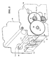
- the open pick area 56 aligns with an associated pick unit 44, as illustrated in Fig 4.
- each pick unit 44 comprises a pair of pick wheels 70 for picking individual media items 64 from the open end 56 of the hopper 42, a pair of drive wheels 72 for engaging with a lower surface of a media item and for driving the item towards the exit point 50, and a pair of retard wheels 74 for engaging with an upper surface of a media item and pushing the item downwards and in a direction opposite the exit point 50.
- the retard wheels 74 reduce the possibility of a plurality of items being picked by the pick wheels 70 as a single item.
- the pick wheels 70 are similar to circular arc nose harmonic cams, and are mounted on a pick shaft 76.
- the pick wheels 70 align with the slots 54 so that as the pick wheels 70 rotate, the wheels protrude through the slots 54, engage with a note, and drive the note towards the drive wheels 72.
- the drive wheels 72 are circular and are mounted on a first (drive wheel) shaft 78.
- the drive wheel shaft is driven directly by a motor (not shown).
- the retard wheels are smaller than the drive wheels 72, are circular, have a high friction surface, and are mounted on a second (retard wheel) shaft 80.
- the drive wheel shaft 78 is coupled to a drive mechanism 90 comprising five intermeshed gears.
- a drive wheel gear 92 is mounted on the drive wheel shaft 78 and intermeshes with an idler gear 94 which also intermeshes with a large radius gear surface 95 of a pick wheel double gear 96.
- the other (small radius) gear surface 97 of the pick wheel double gear 96 intermeshes with a common component 98 in the form of a double idler gear.
- the pick wheel double gear 96 is mounted on the pick wheel shaft 76.
- the double idler gear 98 also has two gear surfaces, one having a large radius 100 and intermeshing with the small gear surface 97, the other having a small radius 102.
- the centre of the double idler gear 98 is mounted on a stud 104.
- the small radius 102 intermeshes with a retard wheel gear 106.
- the retard wheel gear 106 is mounted on the retard shaft 80.
- pivot arm 108 One end of a pivot arm 108 is coupled to the retard shaft 80, and the pivot arm 108 is mounted at its pivot point 110 on the stud 104.
- the opposite end of the pivot arm 108 is coupled to a bracket 114 by a spring 116 for urging the retard shaft 80 towards the drive wheel shaft 78.
- the spring 116 is secured to the bracket 114 by a bolt 118 that allows adjustment of the distance the pivot arm 108 can move.
- the retard shaft 80 is free to move within a circular aperture 112 defined in the supporting chassis 82 (which forms part of the dispenser chassis 40).
- the transport mechanism 46 comprises stretchable endless belts and a skid plate arrangement.
- the belts are driven by the motor (not shown) that drives the drive wheel shaft.
- the media thickness sensor 48 comprises a linear variable differential transducer (LVDT) as is well known in the art.
- LVDT linear variable differential transducer
- the media low indicator 49 includes a magnetic sensor (not shown). When the pusher plate 58 in a hopper 42 is within a predetermined distance of the magnetic sensor, then the magnetic sensor detects the magnet 60 in the pusher plate 58 which indicates that there are few media items left in the hopper 42. The media low indictor 49 then notifies the ATM controller module 22 that the hopper 42 requires replenishment with media.
- the pick wheels 70 are rotated to pull a card from the hopper 42.
- the drive wheels 72 and the retard wheels 74 are in the initial position, that is, they are in close proximity or touching each other.
- the card passes between the drive wheels 72 and the retard wheels 74, thereby deflecting the retard wheels 74 upwards and causing pivot arm 108 to pivot about stud 104.
- retard wheel gear 106 remains intermeshed with the double idler gear 98 because the distance between the centres of these gears 98,106 remains constant.
- the retard wheels 74 remain in contact with the upper surface of the card because the retard wheels 74 are biased towards the drive wheels 72, thereby ensuring that multiple cards are not picked.
- the pivot spring 116 urges the retard shaft 80 back to the initial position.
- the circular slot may be arcuate.
- the drive wheel shaft may be resiliently biases rather than, or in addition to, the retard wheel shaft.
- stretchable endless belts may be used for the drive mechanism 90.
Landscapes
- Engineering & Computer Science (AREA)
- Mechanical Engineering (AREA)
- Sheets, Magazines, And Separation Thereof (AREA)
- Feeding And Guiding Record Carriers (AREA)
Applications Claiming Priority (2)
| Application Number | Priority Date | Filing Date | Title |
|---|---|---|---|
| GBGB0025429.2A GB0025429D0 (en) | 2000-10-17 | 2000-10-17 | Self-service terminal |
| GB0025429 | 2000-10-17 |
Publications (2)
| Publication Number | Publication Date |
|---|---|
| EP1207501A2 true EP1207501A2 (de) | 2002-05-22 |
| EP1207501A3 EP1207501A3 (de) | 2004-03-03 |
Family
ID=9901455
Family Applications (1)
| Application Number | Title | Priority Date | Filing Date |
|---|---|---|---|
| EP01307918A Withdrawn EP1207501A3 (de) | 2000-10-17 | 2001-09-18 | Selbstbedienungsterminal |
Country Status (3)
| Country | Link |
|---|---|
| US (1) | US6626426B2 (de) |
| EP (1) | EP1207501A3 (de) |
| GB (1) | GB0025429D0 (de) |
Families Citing this family (7)
| Publication number | Priority date | Publication date | Assignee | Title |
|---|---|---|---|---|
| US6938896B2 (en) * | 2001-02-22 | 2005-09-06 | Asahi Seiko Co., Ltd | Automatic card dispensing unit with display capability |
| US7140607B2 (en) * | 2002-10-18 | 2006-11-28 | Diebold Self-Service Systems Division Of Diebold, Incorporated | Cash dispensing automated banking machine with note unstacking and validation |
| US7789387B2 (en) * | 2008-12-22 | 2010-09-07 | Pitney Bowes Inc. | Roller assembly for feeding stacked sheet material |
| RU209536U1 (ru) * | 2021-04-29 | 2022-03-17 | Общество с ограниченной ответственностью "ЭНЕРГОРЕШЕНИЯ" | Мембрана для аэратора |
| US11721155B2 (en) | 2021-10-27 | 2023-08-08 | Capital One Services, Llc | Financial article processing devices and methods |
| WO2025141230A1 (es) * | 2023-12-27 | 2025-07-03 | Azkoyen, S.A. | Dispositivo de recepción de billetes |
| US12330857B1 (en) * | 2025-01-29 | 2025-06-17 | Prince Mohammad Bin Fahd University | Coaxial multi-disc powder feeder system for multi powder flow and composition control |
Family Cites Families (23)
| Publication number | Priority date | Publication date | Assignee | Title |
|---|---|---|---|---|
| US4443006A (en) * | 1980-07-21 | 1984-04-17 | Billcon Corporation Of America | Document and currency counter |
| JPS5757142A (en) * | 1980-09-19 | 1982-04-06 | Hitachi Ltd | Automatic paper feeding apparatus |
| JPS5831836A (ja) * | 1981-08-21 | 1983-02-24 | Hitachi Ltd | 紙葉類給送装置 |
| JPS58109334A (ja) * | 1981-12-21 | 1983-06-29 | Minolta Camera Co Ltd | シ−ト給送装置 |
| JPS6279134A (ja) * | 1985-09-30 | 1987-04-11 | Toshiba Corp | 電子複写機の給紙装置 |
| US4715593A (en) * | 1985-12-02 | 1987-12-29 | Godlewski Edward S | Stack-supporting bottom feed conveyor |
| US5011128A (en) * | 1988-04-26 | 1991-04-30 | Laurel Bank Machines Co., Ltd. | Apparatus for detecting the thickness of sheets |
| JPH0270634A (ja) * | 1988-09-01 | 1990-03-09 | Konica Corp | 給紙装置 |
| US5172899A (en) * | 1989-04-28 | 1992-12-22 | Seikosha Co., Ltd. | Paper feeder |
| JP2680223B2 (ja) * | 1992-03-03 | 1997-11-19 | シャープ株式会社 | 摩擦分離ローラ型給紙装置 |
| US5351945A (en) * | 1992-05-30 | 1994-10-04 | Mita Industrial Co., Ltd. | Overlapped transfer-preventing mechanism |
| EP0774434B1 (de) * | 1992-06-19 | 2000-05-24 | Canon Kabushiki Kaisha | Vorrichtung zum Zuführen von Bögen |
| JP3211844B2 (ja) * | 1992-11-04 | 2001-09-25 | 富士ゼロックス株式会社 | 給紙装置 |
| JPH06144622A (ja) * | 1992-11-04 | 1994-05-24 | Fuji Xerox Co Ltd | 画像形成装置の用紙搬送装置 |
| JP3180480B2 (ja) * | 1992-11-20 | 2001-06-25 | 富士ゼロックス株式会社 | 画像形成装置の給紙装置 |
| JPH06171784A (ja) * | 1992-12-10 | 1994-06-21 | Canon Inc | 給紙装置 |
| JP3296864B2 (ja) * | 1992-12-18 | 2002-07-02 | 株式会社リコー | 給紙装置 |
| US5301834A (en) | 1993-01-21 | 1994-04-12 | The Lift Ticket | Card vending machine |
| GB9315145D0 (en) * | 1993-07-22 | 1993-09-08 | Ncr Int Inc | Apparatus for indicating the thickness of record media |
| JPH0820449A (ja) * | 1994-07-07 | 1996-01-23 | Eastman Kodak Japan Kk | 用紙搬送装置 |
| JP3331262B2 (ja) * | 1994-07-19 | 2002-10-07 | シャープ株式会社 | 給紙装置 |
| JP3197163B2 (ja) * | 1994-09-19 | 2001-08-13 | キヤノン株式会社 | シート分離装置 |
| US5967504A (en) * | 1997-08-15 | 1999-10-19 | Data Pac Mailing Systems Corp. | Envelope feeder |
-
2000
- 2000-10-17 GB GBGB0025429.2A patent/GB0025429D0/en not_active Ceased
-
2001
- 2001-09-18 EP EP01307918A patent/EP1207501A3/de not_active Withdrawn
- 2001-09-28 US US09/966,025 patent/US6626426B2/en not_active Expired - Lifetime
Also Published As
| Publication number | Publication date |
|---|---|
| US20020043756A1 (en) | 2002-04-18 |
| EP1207501A3 (de) | 2004-03-03 |
| GB0025429D0 (en) | 2000-11-29 |
| US6626426B2 (en) | 2003-09-30 |
Similar Documents
| Publication | Publication Date | Title |
|---|---|---|
| EP1149038B1 (de) | Medienspeicher- und wiederverwendungssystem für geldautomat | |
| US5342165A (en) | Sheet handling apparatus | |
| EP0606959B1 (de) | Gerät zum Deponieren von Artikeln | |
| US10011446B2 (en) | Sheet paper conveyor device and sheet paper handling device | |
| EP1736937B1 (de) | Vorrichtung zur Entnahme von Banknoten aus einem Bankautomat | |
| CN105122319B (zh) | 介质聚集装置和介质处理装置 | |
| US6032948A (en) | Apparatus for stacking sheets | |
| US6626426B2 (en) | Self-service terminal | |
| RU2628510C2 (ru) | Устройство транспортировки носителя и устройство транзакции с носителем | |
| CN104837753B (zh) | 取入送出装置、介质收纳库和介质处理装置 | |
| EP0456814B1 (de) | Blatthandhabungsvorrichtung | |
| EP2450300A1 (de) | Vorrichtung und verfahren zur förderung von notenbündeln und handhabung von papiernoten | |
| JP6679940B2 (ja) | 媒体処理装置及び自動取引装置 | |
| AU2020343703C1 (en) | Banknote deposit-withdrawal system and architecture | |
| JP7849434B2 (ja) | ベゼル及びベゼルを有する紙幣処理装置 | |
| CN104937643B (zh) | 纸页类收纳装置、纸页类处理装置以及纸页类输送装置 | |
| EP1752404B1 (de) | Medienspeicher- und Wiederverwendungssystem für Geldautomat | |
| US20110074089A1 (en) | Media transport | |
| WO2024084788A1 (ja) | 媒体収納庫及び媒体処理装置 | |
| JP5226254B2 (ja) | 景品読取装置 | |
| JP2003085646A (ja) | 硬貨払出装置 | |
| WO2004070668A1 (en) | Device and method for storing value documents | |
| JPS61273694A (ja) | 封筒預り装置 |
Legal Events
| Date | Code | Title | Description |
|---|---|---|---|
| PUAI | Public reference made under article 153(3) epc to a published international application that has entered the european phase |
Free format text: ORIGINAL CODE: 0009012 |
|
| AX | Request for extension of the european patent |
Free format text: AL;LT;LV;MK;RO;SI |
|
| PUAL | Search report despatched |
Free format text: ORIGINAL CODE: 0009013 |
|
| AK | Designated contracting states |
Kind code of ref document: A3 Designated state(s): AT BE CH CY DE DK ES FI FR GB GR IE IT LI LU MC NL PT SE TR |
|
| AX | Request for extension of the european patent |
Extension state: AL LT LV MK RO SI |
|
| RIC1 | Information provided on ipc code assigned before grant |
Ipc: 7B 65H 3/52 B Ipc: 7G 07F 19/00 A |
|
| 17P | Request for examination filed |
Effective date: 20040903 |
|
| AKX | Designation fees paid |
Designated state(s): DE ES FR GB IT |
|
| 17Q | First examination report despatched |
Effective date: 20041210 |
|
| STAA | Information on the status of an ep patent application or granted ep patent |
Free format text: STATUS: THE APPLICATION HAS BEEN WITHDRAWN |
|
| 18W | Application withdrawn |
Effective date: 20070118 |