EP1207095A2 - Direction assistée électrique et procédé pour la fabrication d'une roue dentée pour cette direction - Google Patents
Direction assistée électrique et procédé pour la fabrication d'une roue dentée pour cette direction Download PDFInfo
- Publication number
- EP1207095A2 EP1207095A2 EP01125683A EP01125683A EP1207095A2 EP 1207095 A2 EP1207095 A2 EP 1207095A2 EP 01125683 A EP01125683 A EP 01125683A EP 01125683 A EP01125683 A EP 01125683A EP 1207095 A2 EP1207095 A2 EP 1207095A2
- Authority
- EP
- European Patent Office
- Prior art keywords
- corrugated
- cylinder part
- support body
- electric power
- power steering
- Prior art date
- Legal status (The legal status is an assumption and is not a legal conclusion. Google has not performed a legal analysis and makes no representation as to the accuracy of the status listed.)
- Granted
Links
Images

Classifications
-
- B—PERFORMING OPERATIONS; TRANSPORTING
- B62—LAND VEHICLES FOR TRAVELLING OTHERWISE THAN ON RAILS
- B62D—MOTOR VEHICLES; TRAILERS
- B62D5/00—Power-assisted or power-driven steering
- B62D5/04—Power-assisted or power-driven steering electrical, e.g. using an electric servo-motor connected to, or forming part of, the steering gear
- B62D5/0409—Electric motor acting on the steering column
-
- F—MECHANICAL ENGINEERING; LIGHTING; HEATING; WEAPONS; BLASTING
- F16—ENGINEERING ELEMENTS AND UNITS; GENERAL MEASURES FOR PRODUCING AND MAINTAINING EFFECTIVE FUNCTIONING OF MACHINES OR INSTALLATIONS; THERMAL INSULATION IN GENERAL
- F16H—GEARING
- F16H55/00—Elements with teeth or friction surfaces for conveying motion; Worms, pulleys or sheaves for gearing mechanisms
- F16H55/02—Toothed members; Worms
- F16H55/06—Use of materials; Use of treatments of toothed members or worms to affect their intrinsic material properties
- F16H2055/065—Moulded gears, e.g. inserts therefor
-
- F—MECHANICAL ENGINEERING; LIGHTING; HEATING; WEAPONS; BLASTING
- F16—ENGINEERING ELEMENTS AND UNITS; GENERAL MEASURES FOR PRODUCING AND MAINTAINING EFFECTIVE FUNCTIONING OF MACHINES OR INSTALLATIONS; THERMAL INSULATION IN GENERAL
- F16H—GEARING
- F16H55/00—Elements with teeth or friction surfaces for conveying motion; Worms, pulleys or sheaves for gearing mechanisms
- F16H55/02—Toothed members; Worms
- F16H55/22—Toothed members; Worms for transmissions with crossing shafts, especially worms, worm-gears
-
- Y—GENERAL TAGGING OF NEW TECHNOLOGICAL DEVELOPMENTS; GENERAL TAGGING OF CROSS-SECTIONAL TECHNOLOGIES SPANNING OVER SEVERAL SECTIONS OF THE IPC; TECHNICAL SUBJECTS COVERED BY FORMER USPC CROSS-REFERENCE ART COLLECTIONS [XRACs] AND DIGESTS
- Y10—TECHNICAL SUBJECTS COVERED BY FORMER USPC
- Y10T—TECHNICAL SUBJECTS COVERED BY FORMER US CLASSIFICATION
- Y10T29/00—Metal working
- Y10T29/49—Method of mechanical manufacture
- Y10T29/49462—Gear making
- Y10T29/49467—Gear shaping
- Y10T29/49472—Punching or stamping
-
- Y—GENERAL TAGGING OF NEW TECHNOLOGICAL DEVELOPMENTS; GENERAL TAGGING OF CROSS-SECTIONAL TECHNOLOGIES SPANNING OVER SEVERAL SECTIONS OF THE IPC; TECHNICAL SUBJECTS COVERED BY FORMER USPC CROSS-REFERENCE ART COLLECTIONS [XRACs] AND DIGESTS
- Y10—TECHNICAL SUBJECTS COVERED BY FORMER USPC
- Y10T—TECHNICAL SUBJECTS COVERED BY FORMER US CLASSIFICATION
- Y10T29/00—Metal working
- Y10T29/49—Method of mechanical manufacture
- Y10T29/49462—Gear making
- Y10T29/49467—Gear shaping
- Y10T29/49474—Die-press shaping
-
- Y—GENERAL TAGGING OF NEW TECHNOLOGICAL DEVELOPMENTS; GENERAL TAGGING OF CROSS-SECTIONAL TECHNOLOGIES SPANNING OVER SEVERAL SECTIONS OF THE IPC; TECHNICAL SUBJECTS COVERED BY FORMER USPC CROSS-REFERENCE ART COLLECTIONS [XRACs] AND DIGESTS
- Y10—TECHNICAL SUBJECTS COVERED BY FORMER USPC
- Y10T—TECHNICAL SUBJECTS COVERED BY FORMER US CLASSIFICATION
- Y10T29/00—Metal working
- Y10T29/49—Method of mechanical manufacture
- Y10T29/4998—Combined manufacture including applying or shaping of fluent material
- Y10T29/49982—Coating
- Y10T29/49986—Subsequent to metal working
-
- Y—GENERAL TAGGING OF NEW TECHNOLOGICAL DEVELOPMENTS; GENERAL TAGGING OF CROSS-SECTIONAL TECHNOLOGIES SPANNING OVER SEVERAL SECTIONS OF THE IPC; TECHNICAL SUBJECTS COVERED BY FORMER USPC CROSS-REFERENCE ART COLLECTIONS [XRACs] AND DIGESTS
- Y10—TECHNICAL SUBJECTS COVERED BY FORMER USPC
- Y10T—TECHNICAL SUBJECTS COVERED BY FORMER US CLASSIFICATION
- Y10T74/00—Machine element or mechanism
- Y10T74/19—Gearing
- Y10T74/19642—Directly cooperating gears
- Y10T74/19698—Spiral
- Y10T74/19828—Worm
Definitions
- the present invention relates to an electric power steering apparatus using a motor as a generating source of steering assistance force and a method of manufacturing a gear used for the electric power steering apparatus.
- An automobile is steered by transmitting rotating operation of a steering wheel disposed at the interior of passenger's room to a steering mechanism disposed at the exterior of the room for turning tire wheels for steering (front wheels, in general).
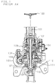
- FIG. 1 is a cross-sectional view showing a constitution of a conventional electric power steering apparatus.
- the figure shows an example of an electric power steering apparatus for an automobile, comprising: a first steering shaft 101 connected to a steering wheel 100 for steering; a second steering shaft 103 connected at one end thereof via a torsion bar 102 to said steering shaft 101 coaxially and at the other end thereof to a steering mechanism joined to tire wheels; a torque sensor 104 for detecting a torque applied on the first steering shaft 101 with rotation of the steering wheel 100 based on torsion generated on the torsion bar 102; a steering assist motor 105 to be driven based on the result of detection of said torque sensor 104; and a reduction mechanism joined to an output shaft of said motor 105 for reducing rotation of said output shaft and transmitting the reduced rotation to the second steering shaft 103.
- Said reduction mechanism has a worm 106 and a worm wheel 107.
- the electric power steering apparatus is constituted to lighten driver's load for steering by assisting the action of the steering mechanism corresponding to rotation of the steering wheel 100 with rotation of the motor 105.
- the worm 106 constituting the reduction mechanism is supported at the interior of a housing 108 via a pair of antifriction bearings (not illustrated).
- the second steering shaft 103 provided with the worm wheel 107 is supported at the interior of the housing 108 via a pair of antifriction bearings 109, 109.
- the worm wheel 107 comprises a ring-shaped tooth body 110 made of synthetic resin which has teeth meshing with the worm 106 and a support body 111 made of metal engaged with the interior side of said tooth body 110.
- the tooth body 110 made of synthetic resin reduces a jarring noise made by meshing with the worm 106 and realizes high workability of the teeth.
- a plurality of locking grooves 114 are provided on a peripheral surface of the support body 111, and prevents relative rotation of the tooth body 110 and the support body 111.
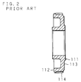
- FIG. 2 is a cross-sectional view showing a constitution of a conventional support body.
- the support body 111 of the worm wheel 107 is formed through cut processing as in FIG. 1 or through cold forging as in FIG. 2.
- the support body 111 formed through cold forging comprises: a cylindrical part 112 engaged with the tooth body 110; a plate part 113 extended inward in a radial direction from one end of said cylindrical part 112; and the locking grooves 114 provided on the peripheral surface of the cylindrical part 112.
- the support body 111 is integrally united with the tooth body 110 by placing the support body 111 in a mold for injection molding and performing injection molding.
- the present applicant has applied an electric power steering apparatus a support body of which is press-formed (Japanese Patent Application Laid-Open No. 2001-206230).
- the engagement part of the press-formed support body with the tooth body comprises a disc part having a plurality of through holes to be filled with synthetic resin for molding the tooth body which penetrate in an axial direction and a curved edge part provided with a plurality of locking grooves which is curved in an axial direction from an exterior edge of said disc part.
- One problem is that the support body is complicated in structure since a relative slide of the tooth body and the support body is hindered at two positions which are the through holes and the curved edge of the engagement part.
- Another problem is that circularity of synthetic resin in the mold for injection molding at the time of molding the tooth body is low since the synthetic resin for molding the tooth body is filled into the through holes of the engagement part, which results in generation of voids and weld marks.
- a support body without the through holes is conceivable.
- Such a support body should have a curved edge which is long in an axial direction provided with locking grooves on the peripheral surface thereof to ensure an enough contact area with the tooth body.
- manufacture of said support body requires use of a relatively expensive and large presser to perform plastic deformation exclusively on the locking groove part on the peripheral surface of the support body. Consequently an amortization expense of the presser is added to a unit price of the support body, and the unit price of the support body amounts to approximately the same as that of the support body provided with the through holes.
- One object of the invention is to provide an electric power steering apparatus with which resin can be deposited uniformly, costs can be reduced, and a corrugated cylinder part can be engaged with a tooth body without generating voids and weld marks.
- Said electric power steering apparatus is constituted with the tooth body made of synthetic resin engaged with the exterior side of the corrugated cylinder part, said corrugated cylinder part being press-formed to deform the support body made of metal engaged with the interior side of said tooth body into a corrugated form corrugating in a peripheral direction.
- Another object of the invention is to provide a method of manufacturing a gear with which a corrugated cylinder part with relatively long concavities can be provided simply by forming the relatively long concavities of the corrugated part with a relatively small presser.
- the corrugated part configured as a corrugated plate is provided by performing press forming on a peripheral side of a metal plate circularly and the corrugated cylinder part is provided by bending said corrugated part into a cylindrical form with respect to a plate part.
- the tooth body made of synthetic resin is integrally molded on the exterior side of said corrugated cylinder part.
- the electric power steering apparatus is constituted to assist steering by transmitting rotation of a steering assist motor to a steering mechanism via a driving gear and a driven gear which has a ring-shaped tooth body made of synthetic resin meshing with said driving gear and a support body made of metal engaged with the interior side of said tooth body.
- the support body of the electric power steering apparatus comprises a corrugated cylinder part press-formed to have a plurality of concavities on the exterior side thereof and convexities to the interior side formed by said concavities which are arranged in a peripheral direction and a plate part an exterior edge of which is united with an end of said corrugated cylinder part.
- synthetic resin for molding the tooth body can appropriately circulate along the concavities on the exterior side of the corrugated cylinder part since the corrugated cylinder part is engaged with the interior side of the tooth body, and the driven gear without voids and weld marks and the electric power steering apparatus using said driven gear are obtained.
- the gear manufactured in the method according to the present invention is fitted to a transmitting shaft for transmitting rotation of the steering assist motor to the steering mechanism.
- the outer peripheral side of the metal plate having the plate part to be mounted with a rotation transmitting system on a center side is press-formed circularly.
- the corrugated part is provided to have a plurality of concavities at one face of the metal plate and convexities to the other face side formed by said concavities which are arranged in a peripheral direction.
- the corrugated cylinder part is provided by bending said corrugated part to be a cylindrical form with respect to the plate part and a ring-shaped tooth body made of synthetic resin is integrally molded on the exterior side of said corrugated cylinder part.
- relatively long concavities of said corrugated part can be formed with a relatively small presser since the corrugated part is provided by performing press forming on the outer peripheral side of the metal plate having the plate part on the center side circularly, that is to say since the corrugated part configured as a corrugated plate is provided on the outer peripheral side of the metal plate. Consequently the method ensures an enough contact area between the tooth body and the support body, and enhances uniting strength between the tooth body and the support body.
- the corrugated cylinder part having relatively long concavities is provided simply since the corrugated cylinder part is provided by bending the corrugated part configured as a corrugated plate with respect to the plate part. Consequently the support body is formed with a relatively small presser, and manufacturing costs of the support body and the gear having said support body can be reduced all the more.
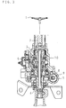
- FIG. 3 is a cross-sectional view showing a constitution of an electric power steering apparatus according to the present invention.
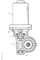
- FIG. 4 is a cross-sectional view showing a constitution of a reduction mechanism and a motor part.
- the electric power steering apparatus comprises: a first steering shaft 2 which is joined at one end thereof to a steering wheel 1 for steering and has a cylinder part at the other end thereof; a torsion bar 3 which is insulted into the interior of the cylinder part and coaxially connected at one end thereof to the other end of the steering shaft 2, the torsion bar 3 being twisted by the action of a steering torque applied on the steering wheel 1; a second steering shaft 4 one end part of which is insulted to the peripheral of the cylinder part and the other end of which is coaxially connected to the other end of the torsion bar 3; a torque sensor 5 for detecting a steering torque applied on the steering wheel 1 based on a relative rotation displacement amount of the first and second steering shafts 2, 4 corresponding to the torsion of the torsion bar 3; a steering assist motor 6 to be driven based on a torque detected by said torque sensor 5; a reduction mechanism 9 interlocking with rotation of the motor 6, which has a driving gear (which is hereafter called a worm)
- the reduction mechanism 9 is arranged to intersect a shaft center of the second steering shaft 4.
- the reduction mechanism 9 comprises the worm 7 made of metal having a shaft part 71 joined to an output shaft 60 of the motor 6 and the worm wheel 8 meshing with said worm 7, which is engaged with and fitted to the middle of the second steering shaft 4. Rotation of the output shaft 60 is reduced by meshing of said worm 7 and worm wheel 8 and transmitted to the second steering shaft 4. The rotation is further transmitted from the second steering shaft 4 via a universal joint (not illustrated) to a steering mechanism (not illustrated) of rack-pinion type, for example.
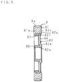
- FIG. 5 is an enlarged cross-sectional view showing a constitution of a worm wheel.
- the worm wheel 8 comprises a ring-shaped tooth body 81 made of synthetic resin having a plurality of teeth 8a meshing with the worm 7 and a support body 82 made of metal engaged with the interior side of said tooth body 81.
- a mounting hole 82a provided at a center part of said support body 82 is engaged with the second steering shaft 4.
- the tooth body 81 made of synthetic resin which is provided at the worm wheel 8 has advantages of reducing a jarring noise made by meshing with the worm 7 and heightening workability of the teeth 8a.
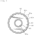
- FIG. 6 is an enlarged side view showing a constitution of a support body.
- FIG. 7 is an enlarged cross-sectional view showing a constitution of the support body.
- the support body 82 comprises: a corrugated cylinder part 83 engaged with the tooth body 81; a disc plate part 84 an exterior edge of which is united with an end of said corrugated cylinder part 83; and a mounting cylinder part 85 which is bent at an interior edge of said plate part 84 to be concentric with the corrugated cylinder part 83.
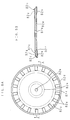
- FIG. 8A is a plan view showing a manufacturing process of the support body of the electric power steering apparatus according to the present invention
- FIG. 8B is a cross-sectional view showing a manufacturing process of the support body, the view being taken on the plane of the line A-A of FIG. 8A
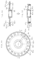
- FIG. 9A is a plan view showing a manufacturing process of the support body of the electric power steering apparatus according to the present invention
- FIG. 9B is a cross-sectional view showing a manufacturing process of the support body, the view being taken on the plane of the line B-B of FIG. 9A
- FIG. 9C is a cross-sectional view of the completely formed support body of the electric power steering apparatus according to the present invention.
- the support body 82 is manufactured as follows.
- a through hole 82b is provided at a center part of a metal plate by performing press forming on said metal plate circularly.
- a ring corrugated part 82c deformed to corrugate in a plate thickness direction and a ring concavity part 82d are provided by press forming respectively on an outer peripheral side and from said corrugated part 82c to an exterior edge.
- a first and a second ring grooves 82f, 82e are provided spaced by press forming at the other face between the through hole 82b and corrugated part 82c (see FIG. 8A and FIG. 8B).
- the mounting cylinder part 85 and plate part 84 are formed by performing press forming on a center side from the second ring groove 82e of the intermediate product press-formed as described above (see FIG. 9A and FIG. 9B).
- the corrugated cylinder part 83 is formed by bending an outer edge side from the first ring groove 82f of the intermediate product to be a cylindrical form with respect to the plate part 84 (see FIG. 9C).
- press forming can be performed with high accuracy without generating a spring back since the mounting cylinder part 85 and corrugated cylinder part 83 are bent at the ring groove parts 82e, 82f.
- the corrugated part 82c is configured as a corrugated plate by performing press forming on the outer peripheral side of the metal plate circularly, relatively long concavities 82g of the corrugated part 82c can be formed with a relatively small presser. Consequently an enough contact area can be ensured between the tooth body 81 and the support body 82, and uniting strength between the tooth body 81 and the support body 82 is enhanced.
- the corrugated cylinder part 83 having relatively long concavities can be provided simply by bending the corrugated part 82c configured as a corrugated plate with respect to the plate part 84. Consequently the support body 82 can be formed with a relatively small presser, and a cost of the support body 82 is reduced all the more.
- the tooth body 81 comprises the teeth 8a and a ring part 81a which supports said teeth 8a. An interior side of said ring part 81a is engaged with and retained at the corrugated cylinder part 83.
- the tooth body 81 is molded by setting the support body 82 as an insert accommodated in a mold for injection molding and injecting melted synthetic resin such as nylon resin from an end part of the corrugated cylinder part 83 to an outer side peripheral and the ring concavity part 82d.
- the tooth body 81 is thus integrally united with the support body 82.
- the synthetic resin is filled from one end part of the corrugated cylinder part 83 to the concavities 82g and the ring concavity part 82d. Filled synthetic resin prevents relative movement both in a peripheral direction and in an axial direction of the tooth body 81 and the support body 82.
- rotation of the steering assist motor 6 is transmitted from the worm 7 via the tooth body 81 meshing with said worm 7 and the worm wheel 8 having the support body 82 engaged with the interior side of said tooth body 81 to the second steering shaft 4.
- the above explanation of the embodiment is on the support body 82 having the mounting cylinder part 85 which is provided at an inner edge of the plate part 84 to be concentric with the corrugated cylinder part 83.
- the reduction mechanism 9 may be constituted without the mounting cylinder part 85 so that the plate part 84 is mounted to the steering shaft 4.
- the reduction mechanism 9 of the embodiment mentioned above may be a hypoid gear comprising a driving gear configured as a hypoid pinion and a driven gear configured as a hypoid wheel in place of the worm gear comprising the driving gear 7 configured as a worm and the driven gear 8 configured as a worm wheel. Further, the reduction mechanism 9 may be configured as a bevel gear.
Landscapes
- Engineering & Computer Science (AREA)
- General Engineering & Computer Science (AREA)
- Mechanical Engineering (AREA)
- Physics & Mathematics (AREA)
- Electromagnetism (AREA)
- Thermal Sciences (AREA)
- Chemical & Material Sciences (AREA)
- Combustion & Propulsion (AREA)
- Transportation (AREA)
- Power Steering Mechanism (AREA)
- Gears, Cams (AREA)
Applications Claiming Priority (2)
| Application Number | Priority Date | Filing Date | Title |
|---|---|---|---|
| JP2000350235 | 2000-11-16 | ||
| JP2000350235A JP3765232B2 (ja) | 2000-11-16 | 2000-11-16 | 電動式パワーステアリング装置及びこれに用いる歯車の製造方法 |
Publications (3)
| Publication Number | Publication Date |
|---|---|
| EP1207095A2 true EP1207095A2 (fr) | 2002-05-22 |
| EP1207095A3 EP1207095A3 (fr) | 2003-06-04 |
| EP1207095B1 EP1207095B1 (fr) | 2004-09-15 |
Family
ID=18823502
Family Applications (1)
| Application Number | Title | Priority Date | Filing Date |
|---|---|---|---|
| EP01125683A Expired - Lifetime EP1207095B1 (fr) | 2000-11-16 | 2001-10-26 | Direction assistée électrique et procédé pour la fabrication d'une roue dentée pour cette direction |
Country Status (4)
| Country | Link |
|---|---|
| US (2) | US6644431B2 (fr) |
| EP (1) | EP1207095B1 (fr) |
| JP (1) | JP3765232B2 (fr) |
| DE (1) | DE60105524T2 (fr) |
Cited By (7)
| Publication number | Priority date | Publication date | Assignee | Title |
|---|---|---|---|---|
| EP1614935A1 (fr) * | 2004-07-07 | 2006-01-11 | Koyo Seiko Co., Ltd. | Roue à vis sans fin et système d'assistance électrique de direction |
| WO2006061104A1 (fr) * | 2004-12-08 | 2006-06-15 | Schaeffler Kg | Poulie a courroie dentee |
| EP1658912A3 (fr) * | 2004-11-19 | 2008-05-07 | REMPEL Stanztechnik GmbH & Co. KG | Méthode de production de la pièce métallique d'une pièce composite en plastique-métal et pièce métallique produit en appliquant cette méthode |
| EP1950122A1 (fr) | 2007-01-26 | 2008-07-30 | Jtekt Corporation | Engrenage et dispositif à direction assistée électrique |
| EP2650561A1 (fr) * | 2010-12-08 | 2013-10-16 | Nhk Spring Co., Ltd. | Élément de sortie et dispositif d'entraînement à arbres multiples |
| CN105324594A (zh) * | 2013-05-31 | 2016-02-10 | 高周波热錬株式会社 | 用于树脂齿轮的金属芯和树脂齿轮组合部件 |
| EP2965971A3 (fr) * | 2014-07-09 | 2016-02-10 | Jtekt Corporation | Système de direction fonctionnant à l'énergie électrique |
Families Citing this family (30)
| Publication number | Priority date | Publication date | Assignee | Title |
|---|---|---|---|---|
| JP3650726B2 (ja) * | 2000-08-08 | 2005-05-25 | 光洋精工株式会社 | 電動パワーステアリング装置 |
| EP1335154B1 (fr) * | 2002-02-04 | 2007-01-03 | JTEKT Corporation | Direction assistée électrique |
| DE10258826A1 (de) * | 2002-12-17 | 2004-07-15 | Ina-Schaeffler Kg | Antriebseinrichtung mit einem Wälzkörpergewindetrieb |
| DE10347780A1 (de) * | 2003-10-15 | 2005-05-12 | Zf Lenksysteme Gmbh | Zahnrad für Schraubradgetriebe |
| JP2005138670A (ja) * | 2003-11-05 | 2005-06-02 | Koyo Seiko Co Ltd | 電動パワーステアリング装置および電動モータの組立方法 |
| JP4356485B2 (ja) * | 2004-03-09 | 2009-11-04 | 株式会社ジェイテクト | 電動パワーステアリング装置 |
| US7930950B2 (en) * | 2005-01-25 | 2011-04-26 | Showa Corporation | Motor-driven steering assist apparatus |
| US20070086907A1 (en) * | 2005-10-19 | 2007-04-19 | Stephan Oberle | Gearwheel and method for manufacturing a gearwheel |
| US7721616B2 (en) * | 2005-12-05 | 2010-05-25 | Gm Global Technology Operations, Inc. | Sprung gear set and method |
| JP2007196751A (ja) * | 2006-01-24 | 2007-08-09 | Jtekt Corp | 電動パワーステアリング装置 |
| US8250940B2 (en) * | 2006-07-20 | 2012-08-28 | Steering Solutions Ip Holding Corporation | System and method for controlling contact between members in operable communication |
| KR100857623B1 (ko) * | 2007-04-30 | 2008-09-09 | 남양공업주식회사 | 전동식 파워 스티어링 장치의 웜휠 구조 |
| JP5145914B2 (ja) * | 2007-12-14 | 2013-02-20 | ソニー株式会社 | コンテンツ視聴管理装置、コンテンツ視聴管理方法、プログラム及びコンテンツ視聴管理システム |
| CN101347887B (zh) * | 2008-08-22 | 2010-06-23 | 常州精棱铸锻有限公司 | 汽车动力转向器的转向臂轴上轮齿的制造方法 |
| EP2376808B1 (fr) * | 2008-12-10 | 2013-01-23 | Vestas Wind Systems A/S | Pièce d engrenage composite destinée à un agencement d engrenage et procédé de formation d une pièce d engrenage composite |
| GB0910046D0 (en) | 2009-06-10 | 2009-07-22 | Glaxosmithkline Biolog Sa | Novel compositions |
| DE102009043367A1 (de) * | 2009-09-29 | 2011-04-07 | Gkn Sinter Metals Holding Gmbh | Anordnung eines Zahnrades und eines Kupplungskörpers zur Übertragung einer Drehbewegung |
| WO2012046868A1 (fr) * | 2010-10-08 | 2012-04-12 | 日本発條株式会社 | Mécanisme de transmission de puissance et dispositif d'entraînement à plusieurs arbres |
| EP2735771B1 (fr) * | 2011-12-07 | 2023-12-06 | NSK Ltd. | Roue à vis sans fin et dispositif de direction à énergie électrique |
| CN103753157A (zh) * | 2013-12-26 | 2014-04-30 | 马钢(集团)控股有限公司 | 一种用于齿轮坯成型的工艺方法及用于齿轮坯成型的轧机 |
| TW201527154A (zh) * | 2014-01-02 | 2015-07-16 | Kwang Yang Motor Co | 車輛電子動力輔助轉向裝置 |
| DE102014106259A1 (de) * | 2014-05-06 | 2015-11-12 | Thyssenkrupp Presta Ag | Lenkwelle für eine Kraftfahrzeuglenkung |
| US20160091052A1 (en) * | 2014-09-25 | 2016-03-31 | Moatech Co., Ltd. | Actuator and electronic equipment having the same |
| CN104439955B (zh) * | 2014-11-17 | 2016-08-24 | 江苏太平洋精锻科技股份有限公司 | 双面结合齿轮成形方法 |
| KR101627311B1 (ko) * | 2015-01-12 | 2016-06-13 | 주식회사 만도 | 스티어링용 감속기의 웜 휠 |
| US10371243B2 (en) * | 2015-06-10 | 2019-08-06 | Bell Helicopter Textron Inc. | Composite and metal hybrid gear |
| KR20170073921A (ko) * | 2015-12-21 | 2017-06-29 | 주식회사 만도 | 자동차의 감속기 |
| ES2835854T3 (es) * | 2016-07-28 | 2021-06-23 | Ims Gear Se & Co Kgaa | Disposición de conexión para conectar un componente tal como un árbol, cubo, buje o similar con una rueda dentada, presentando la rueda dentada un dentado oblicuo |
| CN209335964U (zh) * | 2018-12-07 | 2019-09-03 | Abb 瑞士股份有限公司 | 传动齿轮以及包括其的减速机构 |
| DE102022203534B3 (de) | 2022-04-07 | 2023-08-31 | Zf Friedrichshafen Ag | Zahnrad mit einem dreiteiligen Aufbau |
Citations (1)
| Publication number | Priority date | Publication date | Assignee | Title |
|---|---|---|---|---|
| JP2001206230A (ja) | 2000-01-26 | 2001-07-31 | Koyo Seiko Co Ltd | 電動パワーステアリング装置 |
Family Cites Families (17)
| Publication number | Priority date | Publication date | Assignee | Title |
|---|---|---|---|---|
| US2654944A (en) * | 1950-04-10 | 1953-10-13 | Universal Railway Devices Co | Method of making gears |
| US4077274A (en) * | 1975-09-10 | 1978-03-07 | Boston Gear Inc. | Worm wheel |
| JPS55135265A (en) | 1979-04-07 | 1980-10-21 | Daihatsu Motor Co Ltd | Gear made of resin in engine |
| US4876876A (en) * | 1987-10-27 | 1989-10-31 | Mazda Motor Corporation | Dies for forging gear-shaped part made of sheet metal |
| US5271287A (en) * | 1992-07-28 | 1993-12-21 | Materials Analysis, Inc. | Multi-metal composite gear/shaft |
| DE4232316C1 (de) * | 1992-09-26 | 1994-03-24 | Deutsche Forsch Luft Raumfahrt | Verfahren zum Herstellen von Ringen für Zahnräder mit Innen- und Außenverzahnung sowie Verwendung eines solchen Integralringes zur Herstellung von innen- oder außenverzahnten Zahnrädern |
| JP2652921B2 (ja) * | 1993-02-04 | 1997-09-10 | 株式会社ユタカ技研 | 円筒体用歯形成形金型 |
| US5307705A (en) * | 1993-02-09 | 1994-05-03 | Fenelon Paul J | Stress dissipation gear and method of making same |
| JP3379092B2 (ja) | 1994-02-04 | 2003-02-17 | 日本精工株式会社 | 電動式パワーステアリング装置 |
| JP3604460B2 (ja) | 1995-06-14 | 2004-12-22 | 光洋精工株式会社 | 電動パワーステアリング装置 |
| JPH0989081A (ja) * | 1995-09-28 | 1997-03-31 | Fuji Heavy Ind Ltd | 汎用エンジンの射出成形ギヤ及びその製造方法 |
| US5706694A (en) * | 1996-08-19 | 1998-01-13 | Tesma International Inc. | Plate clutch assembly having a torque transmitting member with an improved lubrication controlling dam structure and method of making the same |
| US6354395B1 (en) * | 1997-08-04 | 2002-03-12 | Delphi Technologies, Inc. | Delashed worm gear assembly and electric power assist apparatus |
| US5906135A (en) * | 1997-10-08 | 1999-05-25 | Koppy Corporation | Coast clutch with power take off gear |
| JP3562948B2 (ja) * | 1997-10-13 | 2004-09-08 | トヨタ自動車株式会社 | ハイポイドギヤ構造 |
| JP3765209B2 (ja) * | 1999-09-08 | 2006-04-12 | 株式会社ジェイテクト | 電動式舵取装置 |
| JP2001108024A (ja) * | 1999-10-06 | 2001-04-20 | Koyo Seiko Co Ltd | 電動パワーステアリング装置 |
-
2000
- 2000-11-16 JP JP2000350235A patent/JP3765232B2/ja not_active Expired - Fee Related
-
2001
- 2001-10-25 US US09/983,631 patent/US6644431B2/en not_active Expired - Fee Related
- 2001-10-26 EP EP01125683A patent/EP1207095B1/fr not_active Expired - Lifetime
- 2001-10-26 DE DE60105524T patent/DE60105524T2/de not_active Expired - Lifetime
-
2003
- 2003-07-24 US US10/625,601 patent/US6868607B2/en not_active Expired - Fee Related
Patent Citations (1)
| Publication number | Priority date | Publication date | Assignee | Title |
|---|---|---|---|---|
| JP2001206230A (ja) | 2000-01-26 | 2001-07-31 | Koyo Seiko Co Ltd | 電動パワーステアリング装置 |
Cited By (12)
| Publication number | Priority date | Publication date | Assignee | Title |
|---|---|---|---|---|
| EP1614935A1 (fr) * | 2004-07-07 | 2006-01-11 | Koyo Seiko Co., Ltd. | Roue à vis sans fin et système d'assistance électrique de direction |
| US7562601B2 (en) | 2004-07-07 | 2009-07-21 | Jtekt Corporation | Worm wheel and electric power steering system |
| EP1658912A3 (fr) * | 2004-11-19 | 2008-05-07 | REMPEL Stanztechnik GmbH & Co. KG | Méthode de production de la pièce métallique d'une pièce composite en plastique-métal et pièce métallique produit en appliquant cette méthode |
| WO2006061104A1 (fr) * | 2004-12-08 | 2006-06-15 | Schaeffler Kg | Poulie a courroie dentee |
| EP1950122A1 (fr) | 2007-01-26 | 2008-07-30 | Jtekt Corporation | Engrenage et dispositif à direction assistée électrique |
| US8096204B2 (en) | 2007-01-26 | 2012-01-17 | Jtekt Corporation | Gear and electric power steering device |
| EP2650561A1 (fr) * | 2010-12-08 | 2013-10-16 | Nhk Spring Co., Ltd. | Élément de sortie et dispositif d'entraînement à arbres multiples |
| EP2650561A4 (fr) * | 2010-12-08 | 2014-05-21 | Nhk Spring Co Ltd | Élément de sortie et dispositif d'entraînement à arbres multiples |
| CN105324594A (zh) * | 2013-05-31 | 2016-02-10 | 高周波热錬株式会社 | 用于树脂齿轮的金属芯和树脂齿轮组合部件 |
| CN105324594B (zh) * | 2013-05-31 | 2019-08-30 | 高周波热錬株式会社 | 用于树脂齿轮的金属芯和树脂齿轮组合部件 |
| EP2965971A3 (fr) * | 2014-07-09 | 2016-02-10 | Jtekt Corporation | Système de direction fonctionnant à l'énergie électrique |
| US9580101B2 (en) | 2014-07-09 | 2017-02-28 | Jtekt Corporation | Electric power steering system |
Also Published As
| Publication number | Publication date |
|---|---|
| US20020056588A1 (en) | 2002-05-16 |
| US6644431B2 (en) | 2003-11-11 |
| DE60105524T2 (de) | 2005-09-29 |
| DE60105524D1 (de) | 2004-10-21 |
| JP2002145086A (ja) | 2002-05-22 |
| US20040083610A1 (en) | 2004-05-06 |
| US6868607B2 (en) | 2005-03-22 |
| EP1207095A3 (fr) | 2003-06-04 |
| JP3765232B2 (ja) | 2006-04-12 |
| EP1207095B1 (fr) | 2004-09-15 |
Similar Documents
| Publication | Publication Date | Title |
|---|---|---|
| EP1207095B1 (fr) | Direction assistée électrique et procédé pour la fabrication d'une roue dentée pour cette direction | |
| EP1950122B1 (fr) | Engrenage et dispositif à direction assistée électrique | |
| EP1614935B1 (fr) | Roue à vis sans fin et système d'assistance électrique de direction | |
| EP1416180A1 (fr) | Mécanisme d'articulation pour un dispositif de direction assistée | |
| US7367914B2 (en) | Differential housing support member | |
| US7979988B2 (en) | Worm gear unit and method of producing same | |
| JP6201986B2 (ja) | 回転伝達機構及び電動パワーステアリング装置 | |
| JP2006194296A (ja) | 複合ギヤおよびその製造方法、並びに複合ギヤを含む電動パワーステアリング装置 | |
| US20080156574A1 (en) | Electric power steering apparatus and manufacturing method of pinion and/or gear for the same | |
| KR100798513B1 (ko) | 전동파워 스티어링 장치 | |
| EP2738408B1 (fr) | Joint de cardan cruciforme et procédé de production de celui-ci | |
| JP2003065422A (ja) | 歯車、減速歯車機構及び電動式パワーステアリング装置 | |
| US7485064B2 (en) | Releasable enclosure for differential housing | |
| WO2004065824A1 (fr) | Roue a vis sans fin et procede de fabrication | |
| JP2008215558A (ja) | ウォーム歯車装置及びウォームホイールの製造方法 | |
| JP4130129B2 (ja) | 電動式パワーステアリング装置、歯車及び歯車の製造方法 | |
| JP2011255818A (ja) | 電動パワーステアリング装置 | |
| JP4779267B2 (ja) | 電動パワーステアリング装置及びそのウォームホイールの製造方法 | |
| JP2003184995A (ja) | 減速歯車機構及び電動式パワーステアリング装置 | |
| JP7452302B2 (ja) | ステアリングシャフト | |
| JP7283319B2 (ja) | ウォームホイールユニット及びその製造方法、ウォーム減速機 | |
| JP5544281B2 (ja) | 減速ギヤの製造方法 | |
| JP2003160052A (ja) | ウォームホイール及びこれを含む電動式動力舵取装置 | |
| KR20150002416A (ko) | 전동식 조향장치의 웜휠 및 그 제조방법 | |
| WO2013153585A1 (fr) | Dispositif de direction assistée électrique |
Legal Events
| Date | Code | Title | Description |
|---|---|---|---|
| PUAI | Public reference made under article 153(3) epc to a published international application that has entered the european phase |
Free format text: ORIGINAL CODE: 0009012 |
|
| AX | Request for extension of the european patent |
Free format text: AL;LT;LV;MK;RO;SI |
|
| PUAL | Search report despatched |
Free format text: ORIGINAL CODE: 0009013 |
|
| AK | Designated contracting states |
Designated state(s): AT BE CH CY DE DK ES FI FR GB GR IE IT LI LU MC NL PT SE TR |
|
| AX | Request for extension of the european patent |
Extension state: AL LT LV MK RO SI |
|
| 17P | Request for examination filed |
Effective date: 20030611 |
|
| GRAP | Despatch of communication of intention to grant a patent |
Free format text: ORIGINAL CODE: EPIDOSNIGR1 |
|
| AKX | Designation fees paid |
Designated state(s): DE FR GB |
|
| GRAS | Grant fee paid |
Free format text: ORIGINAL CODE: EPIDOSNIGR3 |
|
| GRAA | (expected) grant |
Free format text: ORIGINAL CODE: 0009210 |
|
| AK | Designated contracting states |
Kind code of ref document: B1 Designated state(s): DE FR GB |
|
| REG | Reference to a national code |
Ref country code: GB Ref legal event code: FG4D |
|
| REG | Reference to a national code |
Ref country code: IE Ref legal event code: FG4D |
|
| REF | Corresponds to: |
Ref document number: 60105524 Country of ref document: DE Date of ref document: 20041021 Kind code of ref document: P |
|
| ET | Fr: translation filed | ||
| PLBE | No opposition filed within time limit |
Free format text: ORIGINAL CODE: 0009261 |
|
| STAA | Information on the status of an ep patent application or granted ep patent |
Free format text: STATUS: NO OPPOSITION FILED WITHIN TIME LIMIT |
|
| 26N | No opposition filed |
Effective date: 20050616 |
|
| PGFP | Annual fee paid to national office [announced via postgrant information from national office to epo] |
Ref country code: GB Payment date: 20071024 Year of fee payment: 7 |
|
| GBPC | Gb: european patent ceased through non-payment of renewal fee |
Effective date: 20081026 |
|
| PG25 | Lapsed in a contracting state [announced via postgrant information from national office to epo] |
Ref country code: GB Free format text: LAPSE BECAUSE OF NON-PAYMENT OF DUE FEES Effective date: 20081026 |
|
| PGFP | Annual fee paid to national office [announced via postgrant information from national office to epo] |
Ref country code: DE Payment date: 20141023 Year of fee payment: 14 Ref country code: FR Payment date: 20141008 Year of fee payment: 14 |
|
| REG | Reference to a national code |
Ref country code: DE Ref legal event code: R119 Ref document number: 60105524 Country of ref document: DE |
|
| PG25 | Lapsed in a contracting state [announced via postgrant information from national office to epo] |
Ref country code: DE Free format text: LAPSE BECAUSE OF NON-PAYMENT OF DUE FEES Effective date: 20160503 |
|
| REG | Reference to a national code |
Ref country code: FR Ref legal event code: ST Effective date: 20160630 |
|
| PG25 | Lapsed in a contracting state [announced via postgrant information from national office to epo] |
Ref country code: FR Free format text: LAPSE BECAUSE OF NON-PAYMENT OF DUE FEES Effective date: 20151102 |