EP1206406B1 - Spule für band mit hoher geschwindigkeit - Google Patents
Spule für band mit hoher geschwindigkeit Download PDFInfo
- Publication number
- EP1206406B1 EP1206406B1 EP98965406A EP98965406A EP1206406B1 EP 1206406 B1 EP1206406 B1 EP 1206406B1 EP 98965406 A EP98965406 A EP 98965406A EP 98965406 A EP98965406 A EP 98965406A EP 1206406 B1 EP1206406 B1 EP 1206406B1
- Authority
- EP
- European Patent Office
- Prior art keywords
- tape
- reel
- flanges
- winding
- pack
- Prior art date
- Legal status (The legal status is an assumption and is not a legal conclusion. Google has not performed a legal analysis and makes no representation as to the accuracy of the status listed.)
- Expired - Lifetime
Links
Images


Classifications
-
- G—PHYSICS
- G11—INFORMATION STORAGE
- G11B—INFORMATION STORAGE BASED ON RELATIVE MOVEMENT BETWEEN RECORD CARRIER AND TRANSDUCER
- G11B15/00—Driving, starting or stopping record carriers of filamentary or web form; Driving both such record carriers and heads; Guiding such record carriers or containers therefor; Control thereof; Control of operating function
- G11B15/60—Guiding record carrier
- G11B15/66—Threading; Loading; Automatic self-loading
- G11B15/67—Threading; Loading; Automatic self-loading by extracting end of record carrier from container or spool
Definitions
- the subject invention relates to tape winding and packing at high speeds and includes packs of wound tapes having parallel co-planar tape edge sides.
- flange packing the system is constructed so that the medium is guided onto and constrained by a flange on the reel into which the tape is being fed.
- Active steering involves sensing of the tape path and inputting corrective signals to a tape support member driven by an actuator. This latter approach is complex and each of the first two approaches requires tape edge contact and inherently leads to tape edge damage after a number of winds/rewinds especially as the tape speed increased.
- the prior art identified air entrainment between the layers of tape on the take-up reel as the major destabilizing effect in high speed tape winding processes, and as primarily responsible for tape scattering in the resulting tape pack.
- the prior art increased tape tension with increasing tape speeds in an effort to squeeze trapped air from in between all layers of tape forming in the tape winding process.
- the increasing tape tensions of the prior art came to tax the physical strength of the tape, either stretching the tape beyond tolerable limits or restricting the maximum allowable tension and thereby increasing the amplitude of the pack scatter for a given tape speed.
- pack scatter increases accordingly.
- Work along conventional methods of correcting pack scatter would require the application of greater and greater controlling forces to correct greater amplitude scatter at higher tape speeds.
- controlling forces increase, damage to the tape resulting from these controlling forces increases.
- pack scatter would overwhelm conventional methods of correction.
- high tape tension and winding-to-winding misalignment can cause at least temporary and sometimes even a permanent distortion of the tape, thereby affecting if not destroying its information recording, storage and reproducing capability.
- pack scatter will cause successive windings of tape to be hard packed against the upper reel flange and the lower reel flange.
- Unwinding tape from this extreme condition can cause further damage to the tape as the tape drags against the upper and lower reel flanges. Without tape flanges, and under certain conditions even with flanges, extreme pack scatter can cause tape to "jump" off a reel resulting in a jammed tape condition or a broken tape.
- Scattered tape packs are particularly vulnerable to damage during handling and transport. Layers of tape which are unsupported by the edges of neighboring layers of tape are prone to be crushed, resulting in permanent tape damage.
- an apparatus for winding tape having opposite edges into an increasing tape pack about a hub of a tape reel having an axis of rotation comprising:
- the drawings illustrate various systems, apparatus and methods of winding tape at high speeds into packs of wound tape of superior quality having spaced parallel co-planar tape edge sides that are smoother and more scatter-free even after thousands of winding and rewinding operations, than in any prior-art tape pack produced at high speeds in excess of some three meters per second.
- the drawings also illustrate systems wherein tape unwound from and rewound into such packs passes through or past a recording, playback or other tape processing or interacting station at high speeds in excess of some three meters per second much more precisely than in any comparable prior-art system.
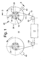
- Figs. 1 and 2 show a linear tape deck and transport arrangement 10, with a block diagram of a tape tension control 12 according to an embodiment of the invention.
- the subject invention and its embodiments are applicable to all kinds of tape drive systems, including tape recording, playback and/or dubbing systems, such as of a magnetic, optical or magneto-optical type, with longitudinal, transverse or helical scan technology, in mono reel, cartridge, dual reel or cassette systems.
- the utility of the invention is not limited to tape recording and the like, but may extend to other applications where ultra precise tape or web guiding, winding and unwinding at high speeds is important or highly beneficial.
- the block 17 in Figs. 1 and 2 symbolizes any tape recording, playback or processing station, as well as any tape drive.
- Tape guide rollers or posts 20 and 120 are also shown on the tape transport between station 17 and alternate tape supply and takeup reels.
- FIG. 1 and 2 illustrate a method of winding tape 13 having opposite edges 14 and 15 into an increasing tape pack 16 about an axis of rotation 18.
- the invention floats substantially each newly arriving winding 113 of the tape 13 on a fluid film 19 on the increasing tape pack 16 and establishes a substantially fluid-free tape pack wherein substantially all corresponding opposite edges 14 and 15 of substantially all tape windings in the tape pack are co-planar along opposite radial planes 21 and 22 (see Fig. 3) of that tape pack 16.
- the invention does so by continuously aligning opposite edges 14 and 15 of substantially each new winding 113 of the tape for a number of turns 23 with corresponding edges of substantially all preceding windings of tape in the increasing tape pack with the aid of the fluid film 19, while gradually diminishing increments of that fluid film between the turns to zero until each leading turn of the number of turns has become locked to a remainder of the tape pack.
- Fig. 3 shows the tape pack and its constituents on an enlarged scale.
- Fig. 3 as well as each of Figs. 5 to 8, 10 to 12 and 14, may be viewed as a section taken on the angled line 3-3 in Fig. 1, except that alignment force imposers or tape edge aligners 32 to 41 and reel flange spreaders 43 to 48 have been added, as more fully described below.
- the left-hand side is the incoming side of the tape 13
- the right-hand side represents the tape packing side.
- Fig. 13 may also be viewed as a section taken on the angled line 3-3 in Fig. 1 or may be viewed simply as a diametral section on a reduced scale relative to the scale of its succeeding Fig. 14.
- Fig. 3 shows the incoming tape 13, a newly arriving winding 113 of that incoming tape, and a remainder of the tape pack 16.
- Fig. 3 also shows the lastly formed fluid film 19 between that newly arriving winding and its preceding winding on the tape pack on which that newly arriving winding 113 floats. Increments of such fluid film extend from in between that newly arriving winding and in between the next preceding windings on the pack for a number of turns 23. As Fig. 3 and some of the other figures graphically illustrate, such fluid film increments diminish as they spiral inwardly into the winding tape pack.
- the above mentioned floating of substantially each newly arriving winding 113 of the tape and the continuous diminution of each fluid film increment is effected by tension control of the winding tape 13.
- the above mentioned floating of substantially each newly arriving winding 113 of the tape 13 on a fluid film 19 on the increasing tape pack 16 may be effected by what we are calling an interwinding fluid film former, since each new fluid film 19 is formed between ("inter") each newly arriving winding 113 and the immediately preceding winding on the increasing tape pack 16, wherefore the expression "interwinding" (between windings) is appropriate.
- the tape tension control 12 is an example of such a fluid film former, as will become more readily apparent in the further course of this disclosure.
- the tape tension control 12 may serve as a tape winding locker coupled to each leading turn of the number of turns of which the newly arriving winding 113 is the last turn.
- such tape winding locker locks each newly arriving tape winding 113 after alignment for a number of turns to the then already tight windings on the tape pack 16.
- Such fluid film former and tape winding locker continuously operate sequentially on winding after winding as the tape pack grows during winding of the tape 13.
- the invention also provides at substantially each of the new windings 113 of the tape 13 and fluid film 19 formed at the increasing tape pack 16 a tape edge aligner or alignment force 31 which with the aid of the fluid film 19 continuously aligns opposite edges 14 and 15 of substantially each new winding 113 of the tape with corresponding edges 14 and 15 of substantially all preceding windings of tape in that increasing tape pack.
- a tape edge aligner or alignment force 31 which with the aid of the fluid film 19 continuously aligns opposite edges 14 and 15 of substantially each new winding 113 of the tape with corresponding edges 14 and 15 of substantially all preceding windings of tape in that increasing tape pack.
- tape alignment force 31 at the unwinding tape pack, so as to indicate that such an alignment force or tape edge aligner can be used at either tape pack, inasmuch as tape 13 may be wound on either side and alternatively be unwound from either side or reel.
- the subject invention goes just the opposite way by positively utilizing a boundary layer of air which 'attaches' to the tape surface during winding and travels with the tape to form the fluid film 19 on the increasing tape pack.
- Such utilization of the forming fluid film in a positive manner is in combination with the continuous alignment of opposite edges 14 and 15 of substantially each new winding 113 of the tape with corresponding edges 14 and 15 of substantially all preceding windings of tape in the increasing tape pack with the aid of such fluid film 19, and the gradual diminution to zero of substantially each fluid film increment that has served as an aid to alignment of corresponding opposite edges 14 and 15 of the tape until each leading turn of the above mentioned number of turns has become locked to a remainder of the tape pack 16, whereby substantially all corresponding opposite edges 14 and 15 of substantially all tape windings in the tape pack will be co-planar along opposite radial planes 21 and 22 of that tape pack, ideally with mirror-like quality.
- Figs. 1 to 12 and 14 show that an aligning of opposite edges 14 and 15 includes imposing on tape 13 a force 31 substantially parallel to fluid film 19 at substantially each of the new windings 113.
- tape edge aligners such as at 32 to 41, as acting on substantially each of the new windings 113 in parallel to fluid film 19.
- the force 31 is imposed with the aid of a pressure differential at tape 13.
- a pressure differential may be generated with what we call a pressure differential generator, such as one of the overpressure generators 33 to 36, or an underpressure generator 39, as or in the tape edge aligner acting on substantially each of the new windings 113 in parallel to the fluid film 19 for a number of turns.
- Fig. 11 symbolically shows the underpressure generator by an arrow 39.
- the underpressure generator 39 in fact may be a sufficiently fast rotation of the tape reel through a reel drive motor 50 with motor control 12 that air or fluid from the fluid film 19 is thrown off by centrifugal force, as indicated by the arrow 38 in Fig. 11, whereby the fluid film is diminished until each newly arriving winding has become locked to the remainder of the tape pack after a number of turns of tape alignment.
- a vacuum pump device or other fluid removal apparatus may be used as the symbolically indicated underpressure generator 39. In either case, the reel flanges are pulled together or contracted into edge alignment contact with each newly arriving tape winding 113 for a number of turns.
- the aligning of the opposite edges 14 and 15 includes tape edge guiding of tape 13 at substantially zero relative motion between tape edge guide and tape at substantially each of the new windings 113 in the illustrated embodiments of the invention.
- the tape edge aligner may include a tape edge guide of substantially zero motion relative to and at substantially each of the new tape windings 113.
- Such zero relative motion may be realized or effected with the aid of reel flanges 26 and 27 with or without further alignment force imposers, such as more fully disclosed below.
- the tape edge guide preferably is rotated with rotation of tape 13 during tape winding.
- the tape edge aligner thus may include a rotary tape edge guide of substantially zero motion relative to and at substantially each of the new windings 113.
- Such rotary tape edge guide may have an axis of rotation 18 substantially parallel to the fluid film 19 formed at the increasing tape pack 16, such as in the case of reel flanges 26 and 27 which rotate about the axis of rotation 18 of the tape reel 28.
- this is only an embodiment of a broader concept pursuant to which the tape edge guide can rotate about any other axis, as long as that produces the substantially zero motion relative to and at substantially each of the new windings 113 of this embodiment of the invention.
- the tape edge guide 41 according to the embodiment shown in Fig. 12 is rotated toward and away from tape 13.
- that rotary tape edge guide 41 has an axis of rotation 42 substantially transverse to the fluid film 19 formed at the increasing tape pack 16, or radial to the axis of rotation 18.
- tape 13 is wound on a hub 29 of a tape reel 28 having flanges 26 and 27 at opposite sides of that hub, and the opposite edges 14 and 15 of substantially each new winding 113 are continuously aligned with such flanges, while the tape reel is in rotation about an axis 18, such as shown in Figs. 1 to 12 and 14.
- the tape edge aligner in apparatus according to this aspect of the invention may include a continuous reel flange flexer coupled to reel flanges 26 and 27. As its given name implies, such reel flange flexer continuously flexes the reel flanges.
- reel flange flexers are shown in Figs. 3 to 12 and 14 at 32 to 41.
- flanges 26 and 27 are continuously flexed onto opposite tape edges 14 and 15 of substantially each new winding 113 such as with the aid or by action of alignment forces 31 or aligners 32 to 41, such as shown in Figs. 1 to 12 and 14.
- flanges 26 and 27 may continuously be flexed apart where tape 13 enters reel 28 during tape winding, such as seen in Figs. 1 to 12 and 14; that is, where tape moves relatively to the reel flanges, or, in other words, where relative motion between tape and reel flange is not substantially zero.
- reel flange spreaders 43 to 48 are respectively shown in Figs. 1 to 12 where the tape 13 enters the reel 28 during tape winding or, for that matter, where the tape exits the reel during unwinding.
- the tape edge aligner in effect may include a reel flange spreader as well, as it does for instance in the embodiment of Fig. 14 where tape edge aligner and reel flange spreader are incorporated in the same structure 32.
- flanges 26 and 27 are continuously flexed onto opposite tape edges 14 and 15 of substantially each new winding 113 while continuously flexing apart where the tape 13 enters the reel during tape winding, as symbolically shown by the double-headed arrow 40 in Fig. 14.
- the flexible reel flanges 26 and 27 according to the embodiment of the invention shown in Figs. 13 and 14 have different spacings at their circumferences or peripheries than at the reel hub 43.
- the flexible reel flanges 26 and 27 may be further apart at their circumferences or peripheries than at the reel hub.
- Such flexible reel flanges may be or may be preformed to be conical.
- conical flanges may be concavely conical or otherwise spread outwardly, such as particularly seen in Fig. 13, or may be convexly conical or spread inwardly to be closer to each other at their peripheries than at hub 29, such as discussed below in conjunction with Fig. 14. Either case invokes the principle set forth in the next paragraph hereof:
- Structures of conical shape including the frustoconical or flattened cone shape of the tape reel flanges 26 and 27, have the characteristic of maintaining a constant circumference at their periphery. In other words, the perimeter of the conical shape stays constant even if the cone is flexed. If the edge of the cone is moved at the periphery to increase or decrease the angle of inclination of the cone relative to the hub 29, such as by rotating the conical flanges 26 and 27 in between the tape aligner pads 65 and 66 for instance or in between other tape edge aligners such as shown in Figs. 5 to 9 and 12, then the shape of such cone must deviate from its original conical shape, such as from its original shape shown in Fig.
- the double-headed arrow 40 symbolizes a reel flange spreader, which could be similar to any of the spreaders 43 to 48 shown in Figs. 1 to 12.
- FIG. 14 in effect is an illustration of both (a) working with a reel flange that so to speak is concavely conical, as shown in Fig. 13, or (b) working with the above mentioned alternative convexly conical reel flange structure. Accordingly, Fig. 14 illustrates two examples wherein tape edge aligner and reel flange spreader are unified in one structure, such as at 32 or at 40, as discussed above.
- the reel flanges may be biased and inherently flexible or may be aided by various flexibility-imposing measures or structures.
- the reel flanges 26 and 27 may be cantilevered or hinged relative to hub 29.
- the flexible reel flanges 26 and 27 may have a series of apertures 51 at the reel hub 29. Such apertures may be in a pattern encircling the hub to increase the flexibility of the flanges relative to that reel hub.
- the flexible reel flanges 26 and 27 have a hinge 52 at the reel hub 29.
- Such hinge may be in the form of a ring of reduced or thin cross-section around the juncture of flange and hub, such as in the form of a so-called 'living hinge' often found in polypropylene parts and other plastics structures.
- the flexible reel flanges 26 and 27 have a concentric convolution 53 at the reel hub 29.
- Such concentric convolution may be of the type used in metal and other diaphragms, such as in aneroid or other bellows, except that preferably only one convolution is used in each reel flange and is situated closely at the reel hub, so as not to interfere with the tape winding and aligning process. This preferably applies to all embodiments shown in Figs. 16 to 20 where, as in Figs. 17 and 19, the hinge 52 or convolution 53 is located substantially outside of the hollow-cylindrical inside surface of the reel hub 29.
- the flexible reel flanges 26 and 27 have radial ridges or other stiffeners 56 at their outsides.
- Such stiffeners may extend from reel hub 29 or from a concentric convolution 53 or other hinge or cantilever structure at the reel hub 29 to an angular margin 57 at the flange periphery where tape alignment force imposers, such as shown in Figs. 3, 8, 9 and 14 at 32 or 36, may be active.
- tape alignment force imposers such as shown in Figs. 3, 8, 9 and 14 at 32 or 36
- the alignment force imposers or tape edge aligners 32 in Figs. 3, 4 and 14 may have a pair of pressure pads 65 and 66 between which the reel flanges 26 and 27 are situated.
- Such pads will be contoured to slope with the flange form where they are in contact with the tape flange 26 or 27 and preferably have a hard smooth finish in contact with the flange, so as to make them long lasting and gentle, and harmless to the flange.
- a finish is available as flame polished sapphire or ceramic or as a hard polished chrome plate.
- the flange spreaders 43 and 44 which contact inward surfaces of the reel flanges, such as shown in Figs. 1 to 4, 10 and 12.
- Alignment force imposers or tape edge aligners may bear against or act on a peripheral region of tape flanges 26 and 27, such as shown for aligner 32 or 36 in the embodiments of Figs. 3, 8 and 14.
- such or other alignment force imposers or tape edge aligners 32 or 33 may in effect follow the periphery of the tape pack 16 as it grows on hub 29 in reel 28, such as shown in Figs. 4 and 5.
- either of such aligners may be mounted on arms 67 or 167 pivoted at 68, such as shown in Fig. 4 which also includes a curved arrow 69 symbolizing a spring bias or driving force for arms 67 and 167.
- such mounting arms of aligners 32 or 33 will be light and spring loaded, and balanced to avoid displacement by small shock or acceleration loads at the tape transport.
- bias 69 will adequately cause aligners 32 to follow the forming tape pack 16 as it grows from near the reel hub 29 to close to the reel periphery.
- a servo control may be used at 69.
- Such controls are known per se and typically use a tape sensor, such as a feeler or a light source-photocell combination that senses the location of each newly forming outer tape winding 113 and that moves the aligners 32 and 33 accordingly, such as with a small motor at 68 or 69 that receives its drive signal in accordance with an output signal of the above mentioned tape sensor.
- Flanges 26 and 27 may be transparent for that purpose and for any other reason as well.
- the tape aligner may be flange-touching, such as the aligner 65, 66 in Figs. 3, 4 and 14, or may be non-touching, such as, for instance, the aligners 33 to 34 shown in Figs. 5 to 9.
- Non-touching tape aligners that provide the necessary push or alignment force 31 include air bearings at each flange 26 and 27. Such air bearings may for instance comprise pads 71 and 72 or bars 73 or 74 with perforations 75 shown for air bearing 35 in Fig. 7, but also implied for the air bearing 33 in Fig. 5 and for other air bearings at 45 shown in Figs. 5 and 7.
- Such air bearings are supplied with air or another desired fluid from a source of compressed air or fluid.
- compressed air or fluid sources are symbolized in Figs. 5, 7 and 11 by fluid supply lines 77 and 78, rather than by boxes symbolizing the fluid supplies themselves.
- air bearing perforations 75 are located on the side of the air bearing or air bearing part facing the flange. Air or other fluid flows from such air bearing at a pressure of a few pounds per square inch (psi) or a pressure on the order of ten kilo pascal.
- the number, size, shape and location of perforations 75 is a design variable.
- the air bars or active air bearing surfaces are located less than a millimeter from each flange surface.
- Air bearings are not the only way of using air to move reel flanges.
- Fig. 6 shows blowers, fans or other air movers 34 and 134 for continually pressing reel flanges 26 and 27 into contact with newly arriving tape windings 113 with the aid of air streams 131 creating alignment forces 31.
- a tape edge aligner 36 includes airfoils 37 and 38 for pushing the reel flanges 26 and 27 continuously toward each other, such as with the kind of airfoil shape shown at 37 in the developed view of Fig. 9, which wedges air moving along with the reel flanges between such foil and adjacent reel flange, thereby generating the requisite tape alignment force 31.
- Fig. 10 shows what we call a centrifugal tape edge aligner 37, since it creates a centrifugal force above the reel flange 26 or below the reel flange 27 which has the effect of pushing such reel flanges toward each other, as indicated by arrows 231.
- a centrifugal tape edge aligner 37 uses weights 81 distributed about the peripheries of the reel flanges 26 and 27 and which have centers of gravity spaced outwardly from outside of such flanges so that inwardly acting flange-bending forces 231 with consequent tape edge alignment forces 31 develop by centrifugal action during rotation of the flanges 26 and 27 or tape reel 28.
- Fig. 10 and the first described version of Fig. 11 are illustrative of an embodiment of the invention wherein tape edge alignment forces 31 are imposed by centrifugal action or, as its given name implies, by centrifugal action alignment force imposers such as shown at 81 in Fig. 10 or at 12 - 50, in Fig. 2 and relevant to the first described version of Fig. 11 generating centrifugal forces at 38, 39 through rapid rotation of the tape reel 28.
- the tape edge aligner 41 shown in Fig. 12 uses or comprises rollers 84 and 85 rotating respectively about axes 42 and 142 that extend radially of or substantially transversely to the axis of rotation 18 or the tape reel 28. Rollers 84 and 85 may contact the reel flanges 26 and 27 so as to be rotatably driven thereby.
- Soft brushes which preferably are conical and rotatably mounted, may be used as rollers 84 and 85.
- the apex of such brush cone points towards the axis 18 of the reel 28 so that if the brush rotates with the flange motion, the surface brush speeds and reel flange speeds will substantially match at all points along the brush. Likewise, if there is slippage it will be uniform along the length of the brush.
- the brush may be soft fibers or elastomeric foam.
- a bristle brush may be positioned so that there is some bending of the soft bristles to give the desired pressure in a less dimensionally crucial way with an allowable small speed difference.
- reel flange spreaders 43 to 48 that continuously spread successive portions of the reel flanges 26 and 27 apart to make room for the incoming tape 13 during winding and for the outgoing tape 13 during unwinding of the tape pack 16.
- This in contrast to the tape edge aligners 32 to 36 which continuously push successive portions of the reel flanges together at a location angularly spaced from the reel flange spreaders or tape entry and exit position, such as by an angle on the order of one-half to one ⁇ rad.
- tape edge aligners 32 to 36 may also be applied to tape spreaders 43 to 48. Accordingly, like reference numerals are employed at components 32 and 44 and 33 and 45 where like or functionally equivalent components may be employed, including pressure pads 65 and 66, or air bearings 71 and 70 and pressurized air or fluid supplies 77 and 78.
- pressure pads 65 and 66 of spreaders 44 contact inside surfaces of reel flanges 26 and 27 to push such flanges outwardly where the tape 13 enters or exits the reel.
- the flange spreader 44 may be angularly displaceable, such as about a central axis of symmetry transversed to the axis of rotation 18 of the tape reel.
- the peripheral shape of such spreader 44 or the peripheral configuration of its pressure pads 65 and 66 may be elliptical or otherwise non-circular, so as to vary and control the degree of spreading of the reel flanges by angular displacement of such spreader.
- air or fluid supplies 77, 78 to air bearings 71 and 72 may be varied so as to vary or control the degree by which the reel flanges are either contracted or distended.
- Spreader 46 in Fig. 6 is similar to tape edge aligner 34, except that it blows air 85 that spreads the reel flanges 26 and 27 apart at the tape entry and exit location. Sometimes a refinement is required in this respect, such as the provision of an angled deflector 86 that guides streams of air or fluid from the supply 77, 78 to in between flanges 26 and 27, in similarity to air bearings 71 and 72.
- the airfoil type of tape aligner 36 also has a counterpart at the flange spreader, such as shown in Figs. 8 and 9.
- spreader 47 may include airfoils 87 and 88 for lifting the reel flanges 26 and 27 continuously away from each other, such as with the kind of airfoil shape shown at 87 in the developed view of Fig. 9, which lifts air moving along with the reel flanges between such foil and adjacent reel flange, thereby generating the requisite reel flange lifting or spreading force.
- the above mentioned floating of substantially each newly arriving winding 113 of tape 13 and the continuous disposal of substantially each fluid film increment that has served as an aid to alignment is effected by a tension control of the winding tape.
- the subject invention prevents such excesses by using tape tensioning to dispose of fluid film increments only in combination with one of the above mentioned alignment techniques which employ the previously disdained fluid film as an aid to tape edge alignment for the achievement of high-quality tape packs according to the invention and its embodiments.
- the tape tension control such as shown at 12 in Fig. 2, preferably imposes a tension on the traveling tape 13 on the order of a thousand pounds per square inch or seven hundred grams per square millimeter during tape winding on either reel.
- prototypes according to the invention have used four ounce tension on half inch wide tape of half mil thickness or hundred fifteen grams on tape of 12.7 millimeter width and thirteen microns (13 ⁇ m) thickness. This is much less than what the prior art imposed on tapes for very high tape speeds.
- the tape tension control system includes reel drive motors 50 and 150 shown in Fig. 2 in conjunction with the tape tension control 12.
- Such control may be in the form of a variable motor control 61 driving tape drive motors 50 and 51.
- Double headed arrows 62 and 63 indicate that tape drive motors 50 and 150 are servo controlled by the variable motor control 61 in the tension control system.
- the desired tape tension for perfect tape alignment and locking in the pack 16 may be realized by restraining unwinding of the tape at the left-hand side of Figs. 1 and 2 while driving the tape for its winding at the right-hand side into the desired tape pack 16.
- Motor control 61 may be varied, until the proper balancing between that tape driving force and that tape unwinding restraint has been realized for the desired tape tension.
- the resulting lower tension on the tape compared to certain high speed prior-art tape winding efforts, in combination with a relatively low aligning force at the tape edges and substantially no relative motion between tape edge aligners and tape edge render tape edge wear and any other tape damage negligible if not practically undetectable.
- control 12 may also include a tape drive, such as a conventional drive of the type that rotates a capstan in engagement with the tape 13 for propulsion thereof, as symbolized by the phantom line 112 in Fig. 2.
- a tape drive such as a conventional drive of the type that rotates a capstan in engagement with the tape 13 for propulsion thereof, as symbolized by the phantom line 112 in Fig. 2.
- Reel flanges 26 and 27 may have a thickness on the order of fifty to five hundred microns ( ⁇ m) depending on application.
- steel or plastics may be used as reel flange material.
- magnetic fields may be used with reel flanges that are of or include ferromagnetic or at least electrically conductive material that permit generation of counter magnetic fields through eddy currents and the like, for tape edge alignment by flange contraction and/or for flange distention at the tape entry and exit region. Electrostatic or piezoelectric phenomena may also be employed where they do not interfere with any tape recording, playback or processing feature in particular cases.
- the invention resides also in packs 16 of wound tape 13 having perfectly co-planar tape edges 14 and 15 at opposite radial sides 21 and 22 of the packs, as produced by the method of the invention or by embodiments thereof, such as herein disclosed and such as illustrated in the accompanying drawings by way of example.
- Recording track densities on the order of a hundred to several thousand tracks per millimeter may be realized with the techniques of the subject invention.
- the flanges used and/or the packs produced by the subject invention and embodiments thereof may be implemented in tape packs, reels, cartridges and cassettes and in other combinations.
Claims (18)
- Vorrichtung zum Wickeln von Band (13) mit gegenüberliegenden Rändern (14, 15) zu einem zunehmenden Bandwickel (16) um eine Nabe (29) einer Bandspule (28), die eine Drehachse (18) aufweist, mit:dadurch gekennzeichnet, daß sie ferner aufweist:einer Einrichtung (12, 61) zum Bilden eines Fluidfilms zwischen Wicklungen, die mit dem Band und durch im wesentlichen jede neu ankommende Wicklung (113) des Bandes (13) über eine Anzahl von Umdrehungen (23) mit dem Bandwickel (16) gekoppelt ist;einer Bandwicklungsfixiereinrichtung (12, 61), die mit jeder führenden Umdrehung der Anzahl von Umdrehungen gekoppelt ist;wobei die Bandrandausrichteinrichtung und die Bandwicklungsfixiereinrichtung die flexiblen Spulenflansche (26, 27) und eine durchgehende Spulenflanschbiegeeinrichtung (32, 40, 43-48) aufweisen, die mit den flexiblen Spulenflanschen gekoppelt ist.flexible Spulenflansche (26, 27) an gegenüberliegenden Seiten der Nabe (29),eine Bandrandausrichteinrichtung (31 bis 42; 65, 66) an im wesentlichen jeder neu ankommenden, auf dem zunehmenden Bandwickel (16) gebildeten Wicklung (113) des Bandes (13) und des Fluidfilms (19);
- Vorrichtung nach Anspruch 1, bei der die Flansche (26, 27) an der Nabe (29) freitragend ausgebildet sind.
- Vorrichtung nach Anspruch 1, bei der die flexiblen Spulenflansche (26, 27) an der Spule (29) eine Reihe von Öffnungen aufweisen.
- Vorrichtung nach Anspruch 1, bei der die flexiblen Spulenflansche (26, 27) an der Nabe (29) angelenkt sind.
- Vorrichtung nach Anspruch 1, bei der die flexiblen Spulenflansche (26, 27) eine konzentrische Krümmung an der Nabe (29) aufweisen.
- Vorrichtung nach Anspruch 1, bei der die flexiblen Spulenflansche (16, 27) an ihren Umfängen andere Abstände voneinander aufweisen als an der Nabe (29).
- Vorrichtung nach Anspruch 1, bei der die flexiblen Spulenflansche (26, 27) an ihren Umfangsrändern weiter voneinander entfernt sind als an der Spule (29).
- Vorrichtung nach Anspruch 1, bei der die flexiblen Spulenflansche (26, 27) konisch sind.
- Vorrichtung nach Anspruch 1, mit einem Spulenflanschspreizer (43 bis 48) an der Stelle, an der das Band (13) während des Wickelns in die Spule eintritt.
- Vorrichtung nach Anspruch 1, bei der die Bandrandausrichteinrichtung (31 bis 42) einen Spulenflanschspreizer (43 bis 48) an der Stelle aufweist, an der das Band während des Wickelns in die Spule eintritt.
- Vorrichtung nach Anspruch 1, bei der die Ausrichteinrichtung (31 bis 42) eine Ausrichtkraftaufbringeinrichtung aufweist, welche über die Flansche auf im wesentlichen jede der neu ankommenden Wicklungen (113) parallel zum Fluidfilm (19) einwirkt.
- Vorrichtung nach Anspruch 1, bei der die Ausrichteinrichtung (31 bis 42) eine Druckdifferenzerzeugungseinrichtung aufweist, die über die Flansche auf im wesentlichen jede der neu ankommenden Wicklungen (113) parallel zum Fluidfilm (19) einwirkt.
- Vorrichtung nach Anspruch 1, bei der die Ausrichteinrichtung (31 bis 42) eine Überdruckerzeugungseinrichtung (33 bis 36) aufweist, die über die Flansche auf im wesentlichen jede der neu ankommenden Wicklungen (113) parallel zum Fluidfilm (19) einwirkt.
- Vorrichtung nach Anspruch 1, bei der die Ausrichteinrichtung (31 bis 42) eine Unterdruckerzeugungseinrichtung (39) aufweist, die über die Flansche auf im wesentlichen jede der neu ankommenden Wicklungen (113) parallel zum Fluidfilm (19) einwirkt.
- Vorrichtung nach Anspruch 1, bei der die Ausrichteinrichtung (31 bis 42) eine Zentrifugal-Bandrandausrichteinrichtung umfaßt.
- Vorrichtung nach Anspruch 1, bei der die flexiblen Spulenflansche (26, 27) radiale Versteifungen (56) aufweisen.
- Vorrichtung nach Anspruch 1, bei der die Einrichtung (12, 61) zum Bilden eines Fluidfilms zwischen Wicklungen und die Bandwicklungsfixiereinrichtung eine Bandspannungssteuerung (12) aufweisen.
- Vorrichtung nach Anspruch 1, bei der der Fluidfilm (19) eine Grenzschicht aus Luft aufweist.
Applications Claiming Priority (1)
| Application Number | Priority Date | Filing Date | Title |
|---|---|---|---|
| PCT/US1998/026910 WO2000035796A1 (en) | 1998-12-17 | 1998-12-17 | High speed tape packing |
Publications (3)
| Publication Number | Publication Date |
|---|---|
| EP1206406A1 EP1206406A1 (de) | 2002-05-22 |
| EP1206406A4 EP1206406A4 (de) | 2002-09-18 |
| EP1206406B1 true EP1206406B1 (de) | 2005-12-14 |
Family
ID=22268496
Family Applications (1)
| Application Number | Title | Priority Date | Filing Date |
|---|---|---|---|
| EP98965406A Expired - Lifetime EP1206406B1 (de) | 1998-12-17 | 1998-12-17 | Spule für band mit hoher geschwindigkeit |
Country Status (5)
| Country | Link |
|---|---|
| EP (1) | EP1206406B1 (de) |
| JP (1) | JP2002538057A (de) |
| CN (1) | CN1153726C (de) |
| DE (1) | DE69832826T2 (de) |
| WO (1) | WO2000035796A1 (de) |
Families Citing this family (1)
| Publication number | Priority date | Publication date | Assignee | Title |
|---|---|---|---|---|
| JP4074566B2 (ja) * | 2003-07-31 | 2008-04-09 | 富士フイルム株式会社 | テープの巻き取り方法 |
Family Cites Families (24)
| Publication number | Priority date | Publication date | Assignee | Title |
|---|---|---|---|---|
| US2529501A (en) * | 1947-04-02 | 1950-11-14 | Wayburn E Johnston | Reel for motion-picture film and the like |
| GB738542A (en) * | 1952-09-11 | 1955-10-12 | Webster Chicago Corp | Improvements in and relating to spools for magnetic tape recorders |
| US3342435A (en) * | 1966-04-11 | 1967-09-19 | Data Packaging Corp | Reel with tape guide |
| US3399845A (en) * | 1966-11-10 | 1968-09-03 | Bell & Howell Co | Take-up reel having variably torqued sprocket ring |
| DE1263499B (de) * | 1967-05-12 | 1968-03-14 | Agfa Gevaert Ag | Schmalfilmkassette mit koaxial angeordneten Wickelkernen |
| US3556435A (en) * | 1968-05-20 | 1971-01-19 | Eastman Kodak Co | Film-threading apparatus |
| US3620477A (en) * | 1969-05-14 | 1971-11-16 | Edward Michael Penn | Data processing tape ring cartridge |
| US3856228A (en) * | 1970-04-08 | 1974-12-24 | Matsushita Electric Ind Co Ltd | Tape reel |
| US3627230A (en) * | 1970-08-27 | 1971-12-14 | Eastman Kodak Co | Apparatus for feeding strip material |
| US3819124A (en) * | 1971-06-23 | 1974-06-25 | Minnesota Mining & Mfg | Cushion flange reel |
| US3768750A (en) * | 1971-12-30 | 1973-10-30 | Paulman Inc | Automatic threading film reel |
| US3749328A (en) * | 1972-02-07 | 1973-07-31 | J Dusenbery | Apparatus for winding thin film into a roll |
| JPS56113643A (en) * | 1980-02-07 | 1981-09-07 | Nippon Telegr & Teleph Corp <Ntt> | Supporting and guiding mechanism for tape |
| US4564411A (en) * | 1983-12-13 | 1986-01-14 | Gaylord Bros., Inc. | Apparatus for producing labels |
| JPS6231645A (ja) * | 1985-07-30 | 1987-02-10 | Fuji Photo Film Co Ltd | 磁気テ−プ巻取り方法および装置 |
| JPS62234286A (ja) * | 1986-04-04 | 1987-10-14 | Fuji Photo Film Co Ltd | 磁気テ−プ巻取方法及び装置 |
| JPH0778982B2 (ja) * | 1988-06-03 | 1995-08-23 | 富士写真フイルム株式会社 | 磁気テープの巻込方法 |
| US5547146A (en) * | 1991-03-18 | 1996-08-20 | Fuji Photo Film Co., Ltd. | Apparatus for winding a magnetic tape on a flanged reel |
| DE9302492U1 (de) * | 1993-02-20 | 1993-04-15 | Basf Magnetics Gmbh, 6800 Mannheim, De | |
| US5474253A (en) * | 1993-10-12 | 1995-12-12 | Quantum Corporation | Wedged reels in streaming tape drivers and tape cartridges |
| JP3003378U (ja) * | 1994-04-20 | 1994-10-18 | 富士写真フイルム株式会社 | テープリール |
| US5533690A (en) * | 1994-06-02 | 1996-07-09 | Minnesota Mining And Manufacturing Company | Strand alignment devices for high speed winding of magnetic tape |
| JP3498884B2 (ja) * | 1996-09-20 | 2004-02-23 | 富士写真フイルム株式会社 | 磁気テープカセット用リール |
| US5803388A (en) * | 1996-11-15 | 1998-09-08 | Quantum Corporation | Tape reel with flange sections for uniform tape stacking |
-
1998
- 1998-12-17 WO PCT/US1998/026910 patent/WO2000035796A1/en active IP Right Grant
- 1998-12-17 EP EP98965406A patent/EP1206406B1/de not_active Expired - Lifetime
- 1998-12-17 DE DE69832826T patent/DE69832826T2/de not_active Expired - Fee Related
- 1998-12-17 CN CNB988143941A patent/CN1153726C/zh not_active Expired - Fee Related
- 1998-12-17 JP JP2000588068A patent/JP2002538057A/ja active Pending
Also Published As
| Publication number | Publication date |
|---|---|
| EP1206406A4 (de) | 2002-09-18 |
| CN1340023A (zh) | 2002-03-13 |
| JP2002538057A (ja) | 2002-11-12 |
| DE69832826D1 (de) | 2006-01-19 |
| DE69832826T2 (de) | 2006-09-07 |
| EP1206406A1 (de) | 2002-05-22 |
| WO2000035796A1 (en) | 2000-06-22 |
| CN1153726C (zh) | 2004-06-16 |
Similar Documents
| Publication | Publication Date | Title |
|---|---|---|
| US6719238B1 (en) | High speed tape packing | |
| US4335857A (en) | Web aligning system | |
| JP4787354B2 (ja) | テープを巻くためのリールおよびテープカートリッジ | |
| US3850358A (en) | Continuous compliant guide for moving web | |
| US5474253A (en) | Wedged reels in streaming tape drivers and tape cartridges | |
| US4474320A (en) | Air bearing for tape drives | |
| US6450438B1 (en) | Apparatus and methods for forming a tape pack | |
| EP1206406B1 (de) | Spule für band mit hoher geschwindigkeit | |
| JPS5870464A (ja) | 弾性ベルト駆動手段およびテ−プとベルトの別個の遊び車を有する磁気テ−プ・カ−トリツジ | |
| JP2004224570A (ja) | リール、テープ駆動装置、ならびにテープを案内するための方法 | |
| US5865389A (en) | Entrainment air dam | |
| US6508431B1 (en) | Guide packing recording media along with cartridges and apparatus incorporating such guides | |
| US20040140392A1 (en) | Butterfly tape reel | |
| US7077354B2 (en) | Edge guiding tape reel | |
| US20060175450A1 (en) | Passive air bearing tape guide | |
| EP0590089A1 (de) | Schraubenlinienförmiger bandabtaster | |
| US3979541A (en) | Thin base self-tracking recording tape | |
| GB2117354A (en) | Magnetic tape guiding system | |
| US7147180B1 (en) | Tape reel with self-generating negative pressure | |
| JP3525707B2 (ja) | 回転ヘッド装置 | |
| CA1182560A (en) | Web aligning system | |
| JPH0258695B2 (de) | ||
| CS196320B2 (en) | Rotor like the bearer of the magnetic head for recording mechanism of the magnetic tape memory | |
| JPS5834606Y2 (ja) | 磁気記録再生装置 | |
| JPS5870465A (ja) | 弾性ベルト駆動手段を有する磁気テ−プ・カ−トリツジ |
Legal Events
| Date | Code | Title | Description |
|---|---|---|---|
| PUAI | Public reference made under article 153(3) epc to a published international application that has entered the european phase |
Free format text: ORIGINAL CODE: 0009012 |
|
| 17P | Request for examination filed |
Effective date: 20010922 |
|
| A4 | Supplementary search report drawn up and despatched |
Effective date: 20020806 |
|
| AK | Designated contracting states |
Kind code of ref document: A4 Designated state(s): DE FR GB |
|
| RIC1 | Information provided on ipc code assigned before grant |
Free format text: 7B 65H 23/00 A, 7G 11B 15/66 B, 7G 11B 15/67 B, 7G 11B 15/60 B |
|
| 17Q | First examination report despatched |
Effective date: 20040625 |
|
| GRAP | Despatch of communication of intention to grant a patent |
Free format text: ORIGINAL CODE: EPIDOSNIGR1 |
|
| GRAS | Grant fee paid |
Free format text: ORIGINAL CODE: EPIDOSNIGR3 |
|
| GRAA | (expected) grant |
Free format text: ORIGINAL CODE: 0009210 |
|
| AK | Designated contracting states |
Kind code of ref document: B1 Designated state(s): DE FR GB |
|
| REG | Reference to a national code |
Ref country code: GB Ref legal event code: FG4D |
|
| REF | Corresponds to: |
Ref document number: 69832826 Country of ref document: DE Date of ref document: 20060119 Kind code of ref document: P |
|
| PGFP | Annual fee paid to national office [announced via postgrant information from national office to epo] |
Ref country code: DE Payment date: 20060228 Year of fee payment: 8 |
|
| PG25 | Lapsed in a contracting state [announced via postgrant information from national office to epo] |
Ref country code: GB Free format text: LAPSE BECAUSE OF NON-PAYMENT OF DUE FEES Effective date: 20060314 |
|
| PLBE | No opposition filed within time limit |
Free format text: ORIGINAL CODE: 0009261 |
|
| STAA | Information on the status of an ep patent application or granted ep patent |
Free format text: STATUS: NO OPPOSITION FILED WITHIN TIME LIMIT |
|
| 26N | No opposition filed |
Effective date: 20060915 |
|
| GBPC | Gb: european patent ceased through non-payment of renewal fee |
Effective date: 20060314 |
|
| EN | Fr: translation not filed | ||
| PG25 | Lapsed in a contracting state [announced via postgrant information from national office to epo] |
Ref country code: DE Free format text: LAPSE BECAUSE OF NON-PAYMENT OF DUE FEES Effective date: 20070703 |
|
| PG25 | Lapsed in a contracting state [announced via postgrant information from national office to epo] |
Ref country code: FR Free format text: LAPSE BECAUSE OF FAILURE TO SUBMIT A TRANSLATION OF THE DESCRIPTION OR TO PAY THE FEE WITHIN THE PRESCRIBED TIME-LIMIT Effective date: 20070202 |
|
| PG25 | Lapsed in a contracting state [announced via postgrant information from national office to epo] |
Ref country code: FR Free format text: LAPSE BECAUSE OF FAILURE TO SUBMIT A TRANSLATION OF THE DESCRIPTION OR TO PAY THE FEE WITHIN THE PRESCRIBED TIME-LIMIT Effective date: 20051231 |
|
| PG25 | Lapsed in a contracting state [announced via postgrant information from national office to epo] |
Ref country code: FR Free format text: LAPSE BECAUSE OF FAILURE TO SUBMIT A TRANSLATION OF THE DESCRIPTION OR TO PAY THE FEE WITHIN THE PRESCRIBED TIME-LIMIT Effective date: 20051214 |