EP1205286B1 - Vorrichtung zur Herstellung von Einkerbungen in die Flanke von Seitenleisten und ein der Einkerbung entsprechender Querschnitt am Ende der Querleisten zur Herstellung einer Stabverbindung zwischen den Seitenleisten und den Querleiten - Google Patents
Vorrichtung zur Herstellung von Einkerbungen in die Flanke von Seitenleisten und ein der Einkerbung entsprechender Querschnitt am Ende der Querleisten zur Herstellung einer Stabverbindung zwischen den Seitenleisten und den Querleiten Download PDFInfo
- Publication number
- EP1205286B1 EP1205286B1 EP00610130A EP00610130A EP1205286B1 EP 1205286 B1 EP1205286 B1 EP 1205286B1 EP 00610130 A EP00610130 A EP 00610130A EP 00610130 A EP00610130 A EP 00610130A EP 1205286 B1 EP1205286 B1 EP 1205286B1
- Authority
- EP
- European Patent Office
- Prior art keywords
- rest
- cross member
- bar
- guide
- notch
- Prior art date
- Legal status (The legal status is an assumption and is not a legal conclusion. Google has not performed a legal analysis and makes no representation as to the accuracy of the status listed.)
- Expired - Lifetime
Links
Images


Classifications
-
- B—PERFORMING OPERATIONS; TRANSPORTING
- B27—WORKING OR PRESERVING WOOD OR SIMILAR MATERIAL; NAILING OR STAPLING MACHINES IN GENERAL
- B27G—ACCESSORY MACHINES OR APPARATUS FOR WORKING WOOD OR SIMILAR MATERIALS; TOOLS FOR WORKING WOOD OR SIMILAR MATERIALS; SAFETY DEVICES FOR WOOD WORKING MACHINES OR TOOLS
- B27G5/00—Machines or devices for working mitre joints with even abutting ends
- B27G5/04—Machines or devices for working mitre joints with even abutting ends for planing, cutting, shearing, or milling mitre joints
-
- Y—GENERAL TAGGING OF NEW TECHNOLOGICAL DEVELOPMENTS; GENERAL TAGGING OF CROSS-SECTIONAL TECHNOLOGIES SPANNING OVER SEVERAL SECTIONS OF THE IPC; TECHNICAL SUBJECTS COVERED BY FORMER USPC CROSS-REFERENCE ART COLLECTIONS [XRACs] AND DIGESTS
- Y10—TECHNICAL SUBJECTS COVERED BY FORMER USPC
- Y10S—TECHNICAL SUBJECTS COVERED BY FORMER USPC CROSS-REFERENCE ART COLLECTIONS [XRACs] AND DIGESTS
- Y10S83/00—Cutting
- Y10S83/917—Notching
-
- Y—GENERAL TAGGING OF NEW TECHNOLOGICAL DEVELOPMENTS; GENERAL TAGGING OF CROSS-SECTIONAL TECHNOLOGIES SPANNING OVER SEVERAL SECTIONS OF THE IPC; TECHNICAL SUBJECTS COVERED BY FORMER USPC CROSS-REFERENCE ART COLLECTIONS [XRACs] AND DIGESTS
- Y10—TECHNICAL SUBJECTS COVERED BY FORMER USPC
- Y10T—TECHNICAL SUBJECTS COVERED BY FORMER US CLASSIFICATION
- Y10T83/00—Cutting
- Y10T83/04—Processes
- Y10T83/0524—Plural cutting steps
- Y10T83/0572—Plural cutting steps effect progressive cut
-
- Y—GENERAL TAGGING OF NEW TECHNOLOGICAL DEVELOPMENTS; GENERAL TAGGING OF CROSS-SECTIONAL TECHNOLOGIES SPANNING OVER SEVERAL SECTIONS OF THE IPC; TECHNICAL SUBJECTS COVERED BY FORMER USPC CROSS-REFERENCE ART COLLECTIONS [XRACs] AND DIGESTS
- Y10—TECHNICAL SUBJECTS COVERED BY FORMER USPC
- Y10T—TECHNICAL SUBJECTS COVERED BY FORMER US CLASSIFICATION
- Y10T83/00—Cutting
- Y10T83/748—With work immobilizer
- Y10T83/7593—Work-stop abutment
- Y10T83/764—Retractable
-
- Y—GENERAL TAGGING OF NEW TECHNOLOGICAL DEVELOPMENTS; GENERAL TAGGING OF CROSS-SECTIONAL TECHNOLOGIES SPANNING OVER SEVERAL SECTIONS OF THE IPC; TECHNICAL SUBJECTS COVERED BY FORMER USPC CROSS-REFERENCE ART COLLECTIONS [XRACs] AND DIGESTS
- Y10—TECHNICAL SUBJECTS COVERED BY FORMER USPC
- Y10T—TECHNICAL SUBJECTS COVERED BY FORMER US CLASSIFICATION
- Y10T83/00—Cutting
- Y10T83/869—Means to drive or to guide tool
- Y10T83/8878—Guide
- Y10T83/8889—With means to adjust position
-
- Y—GENERAL TAGGING OF NEW TECHNOLOGICAL DEVELOPMENTS; GENERAL TAGGING OF CROSS-SECTIONAL TECHNOLOGIES SPANNING OVER SEVERAL SECTIONS OF THE IPC; TECHNICAL SUBJECTS COVERED BY FORMER USPC CROSS-REFERENCE ART COLLECTIONS [XRACs] AND DIGESTS
- Y10—TECHNICAL SUBJECTS COVERED BY FORMER USPC
- Y10T—TECHNICAL SUBJECTS COVERED BY FORMER US CLASSIFICATION
- Y10T83/00—Cutting
- Y10T83/929—Tool or tool with support
- Y10T83/9411—Cutting couple type
- Y10T83/9442—Notching tool
Definitions
- Machine for the production of a bar notch in the side of a side member and a bar notch at the end of a cross member for a bar joint between a side member and a cross member according to the preamble of claim 1.
- the present invention relates to a machine for the production of a bar notch in the side of a side member and of a cross member notch on the end of a cross member at the joint between a side member and a cross member in workpieces of wood, plastics or MDF - medium density fibreboard -
- the cross member notch preferably has a plane bottom, which is parallel with a side surface in the side member and two equally long, oblique sides, which have oppositely directed equal inclinations in relation to the bottom
- the cross member notch has a plane end in a cross member and two inclined sides, which are of a shape and size such as to make the shaped cross member end fit into the notch.
- a machine which can produce a cross member notch in a vertical and in a horizontal cross member for a window or a door.
- the cross members have identical cross sections of approximately the shape of a cross.
- the two cross members are given a cross sectionally rectangular groove with a plane bottom by means of rotating milling tools, which bottom is oriented in the direction of a side in the cross member, and which is of approximately the same shape as the cross member notches, which are to be produced by a machine according to the invention.
- the milled groove is performed by a special tool in the machine.
- both cross members of the cross is shaped with oblique surfaces by a punching operation with a special tool in the machine consisting of two knives forming a mutually arranged angle guided in its vertical motion.
- This machine is complicated in its construction and is difficult to set up and operate.
- the cross member notches and the side member notches are produced by a first step - a preliminary step - and a second step - a final cut or smoothing operation. This is to avoid fraying of the material.
- Claim 2 deals with a first set of adjustable guide members for a machine according to the invention.
- Claim 3 deals with a second set of adjustable guide members for a machine according to the invention.
- Claim 4 describes a preferred embodiment of a stop for the second set of adjustable guide members.
- Claim 5 describes a third guide member for a machine according to the invention.
- Claim 6 describes a preferred method of mounting of a dolly for a machine according to the invention.
- Claim 7 describes how to produce a notch for a cross member by a simple punching or shearing operation.
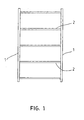
- a frame for example for doors or gates, consists of two side members 1 and of a number of cross members 2.
- the side members 1 and the cross members 2 are joined in bar joints consisting of a bar notch into the side of a side member 1 and a cross member notch 4 at the end of a cross member 2.
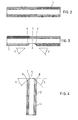
- a side member notch can have a plane bottom 5, which is parallel with a side surface 1' of the side member 1 and two oblique sides 6, which are of equal length and which have two equally large oppositely directed inclines v in relation to the bottom 5.
- a cross member notch 4 consists of a plane end piece 7 at right angles to a side surface 2' in the member 2, and of two equally long oblique sides 8, which have two identical oppositely directed inclines v in relation to the bottom 7.
- the bottom 7 and the sides 8 are of such a length that the shape of the cross member fits into the notch.
- a side member notch 3 and a cross member notch 4 may be produced in one punching or shearing operation with a machine according to the invention.
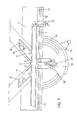
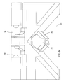
- a machine for the production of side member and cross member cuts by shearing comprises a triangular knife head 9 - viewed from above - for two side knives 10 and a nose knife 11.
- the knife head 9 is movable in the vertical direction in a guide 12. This movement can be effected, for example, by means of of a not shown foot pedal, but it can also be done automatically, for example hydraulically.
- the guide 12 is movable in the horizontal direction towards or away from a workpiece to be worked and which rests against a rest 13 on a table 14. This movement can be effected by activation of a handle 15 on a not shown arm, and the setting can be read on a scale 16. This movement can also be automatic, for example hydraulic.
- the machine comprises a first set of adjustable guide members which can set the position of the knife head 9 in relation to the workpiece 1 or 2, which is to be processed, accurately during the shearing operation.
- These guide members can consist of two stops 17, which each are displaceably mounted on a guide rail 18, which is mounted on the knife head 9, each along its own side knife 10 and parallel with them.
- the stops 17 have an inside edge 20, which in its mounted position rests against the outside of the side knives 10 and a plane front side 21, which is parallel with the rest 13 and can come to rest against the workpiece 1 or 2, which is to be processed.
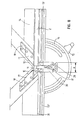
- the machine also comprises a second set of of adjustable guide members for the setting of the distance between the bar notches, which are sheared into the side of a side member 1.
- the rest 13 is embodied as a guide rail with a vertical, longitudinal guide list 22 at the rear end.
- the second set of guide members consists of a number of stops 23, which are displaceable along the rest 13 and can be clamped to it by a knob-head bench screw 24.
- Each stop 23 has at its rear end - at the guide list 22 - a lower part 25 with a U-shaped opening 26, which can accommodate the lower edge of the guide list 22, and an upper part 27, which is embodied as a fork, which in its mounted position reaches in over the whole width of the rest 13.
- An arm 28, which can be received in the fork 27, is at one end embodied with a stop 28' against which the end of a workpiece 1, which is to be processed, can come to rest.
- the arm 28 is swingably hinged to the upper part 27 by a pin 28", so that it can be swung over to a passive position.
- the third guide members consists of a catch 29, which can be moved crosswise to the rest 13 in a guide 30, which is mounted on the table 14 in the space a.
- the catch 29 can be displaced to adopt a forward working position in which it protrudes a distance forward over the front edge 31 of the rest 13, and in which it serves as a rest for the end of a cross member 2 during the punching of a cross member notch 4. From this position the catch 29 can be displaced to a retracted, passive position behind the front edge of the rest.
- the catch can be fixed to the table 14 by means of a clamping arrangement 32.
- indentation 33 there is an indentation 33 in the table 14 under the set of knives 10,10,11.
- the cutting edge of the side knives 10 and the nose knife 11 can therefore in their bottom position be at a level with or slightly lower than the top side of the table 14.
- a detachably mounted dolly 34 of a soft material e.g. of a synthetic material.
- the dolly 34 can be supported by and mounted on a plate member 35 screwed to the machine. The result is that a clean cut can be produced in the workpiece to be processed.
- the nose knife 11 can be of the same width as the bottom 5 in a cross member notch 3. Consequently, there is no need to displace the bar 1 lengthwise along the rest 13 during the shearing of a cross member notch 3.
- the nose knife shown in figs. 11 and 12 with a V-shaped notch is employed for narrow workpieces.
- the plane front side 21 of the guide members 17 is held at a short distance from the side of the bar to be processed.
Claims (7)
- Vorrichtung zur Herstellung von Einkerbungen (3) in der Flanke von Seitenleisten (1) und einem der Einkerbung entsprechenden Querschnitt (4) am Ende der Querleiste (2) zur Herstellung einer Stabverbindung zwischen den Seitenleisten (1) und den Querleisten (2) in Werkstücken aus Holz, Kunststoff oder MDF - Mitteldichte Faserplatte - bestehend aus einem Messerkopf (9) für zwei Seitenmesser (10), die in einer Führung (12) in Richtung hin zu oder weg von dem zu bearbeitenden, an einem Anschlag (13) am Tisch (14) anliegenden Werkstück (1) oder (2) senkrecht verschiebbar sind,
dadurch gekennzeichnet,
dass der Messerkopf (9) in der Oberansicht eine Dreieckform aufweist und mit einem Vordermesser (11) ausgestattet ist, und dass sich die Führung (12) in waagerechte Richtung hin zu oder weg von dem zu bearbeitenden Werkstück (1) oder (2) verschieben lässt, und dass die Vorrichtung mit einem ersten Satz von einstellbaren Führungselementen (17) zur Einstellung der Position des Messerkopfs (9) in der waagerechten Richtung im Verhältnis zu dem während des Schneideverfahrens exakt zu bearbeitenden Werkstück (1) oder (2) und mit einem zweiten Satz von auf dem Anschlag (13) montierten einstellbaren Führungselementen (23) zur Einstellung des Abstands zwischen den Einkerbungen (3) und mit einem dritten als Endanschlag für die Querleiste bei der Schneidung eines Querschnitts (4) funktionierenden Führungselement (29) ausgestattet ist, und dass der Tisch (14) eine Auszackung (33) aufweist, die eine niveaugleiche oder leicht abgesenkte Anordnung der unteren Schneiden der zwei Seitenmesser (10) und des Vordermessers (11) in der unteren Position im Verhältnis zu der Oberseite des Tisches (14) ermöglicht, und dass die Auszackung (33) mit einem Gegenhalter (34) aus einem weichen Material, z.B. einem synthetischen Material, ausgestattet ist. - Vorrichtung nach Anspruch 1,
dadurch gekennzeichnet,
dass der erste Satz von einstellbaren Führungselementen aus zwei auf einer am Messerkopf (9) montierten Führungsschiene (18) angeordneten Anschlagklötzen (17) besteht, jeweils auf einer Seite des Seitenmessers verschiebbar angeordnet und mit Schrauben (19) in gewünschter Position an einer Führungsschine (18) befestigt, welche Anschlagklötze (17) eine an der Außenseite eines Seitenmessers (10) anliegenden Innenkante (20) und eine ebene, mit dem Anschlag (13) parallel liegende Stirnseite (21), die gegen das zu bearbeitende Werkstück (1) oder (2) anliegen kann, aufweisen. - Vorrichtung nach Anspruch 1,
dadurch gekennzeichnet,
dass der Anschlag (13) als eine Führungsschiene mit einer Längenführung (22) am hinteren Ende gestaltet ist, und dass der zweite Satz von einstellbaren Führungselementen aus Anhaltevorrichtungen (23) besteht, die sich in der Längsrichtung des Anschlags (13) verschieben lassen und mittels einer Spannschraube (24) mit Griff in gewünschter Position daran befestigt werden können, und dass die Anhaltevorrichtung (23) mit einem schwenkbaren Arm (28) ausgestattet ist, der von einer aktiven Stellung - in der eine Anhaltevorrichtung (28') am Ende des Arms an das Ende des zu bearbeitenden Werkstücks (1) anliegen kann - in eine passive Stellung geschwenkt werden kann. - Vorrichtung nach Anspruch 3,
dadurch gekennzeichnet,
dass die Anhaltevorrichtung (23) am hinteren Ende an der Längenführung (22) einen unteren Teil mit einer U-förmigen Öffnung (26) zur Aufnahme der Unterkante der Längenführung (22) und einen gabelförmigen oberen Teil (27), der in montierter Stellung über den Anschlag (13) hinausragt und als Führung für den Arm (28) in dessen aktiven Stellung funktioniert, aufweist, und dass der Arm (28) am Zapfen (28") drehbar am oberen Teil (27) befestigt ist. - Vorrichtung nach Anspruch 1,
dadurch gekennzeichnet,
dass der Anschlag (13) aus zwei Teilen besteht, einem rechten Teil (13') und einem linken Teil (13"), die an der Mitte des Messerkopfs (9) mit einem gegenseitigen Abstand (a) angeordnet sind, und dass das dritte Führungselement aus einer Klinke (29) besteht, die aus Vierkantstahl hergestellt sein kann und die sich quer zum Anschlag (13) in einer auf dem Tisch (14) angeordneten Führung (30) in dem Zwischenraum (a) von einer vorgeschobenen Arbeitsstellung, in der die Klinke (29) ein Stück über die Stirnkante (31) des Anschlags (13) hinausragt und als Anschlag für das Ende einer Querleiste (2) bei der Ausstanzung eines Querschnitts (4) dient, in eine zurückgezogene passive Stellung verschieben lässt, und dass die Klinke (2) mittels einer Spannvorrichtung (32) am Tisch (14) befestigt werden kann. - Vorrichtung nach Anspruch 1,
dadurch gekennzeichnet,
dass der Gegenhalter (34) auf einer Platte (35) abnehmbar montiert ist. - Vorrichtung nach Anspruch 1,
dadurch gekennzeichnet,
dass das Vordermesser (11) dieselbe Breite wie der Boden (5) eines Querschnitts (4) aufweist.
Applications Claiming Priority (2)
| Application Number | Priority Date | Filing Date | Title |
|---|---|---|---|
| DK200001661 | 2000-11-07 | ||
| DK200001661A DK174105B1 (da) | 2000-11-07 | 2000-11-07 | Fremgangsmåde til fremstilling af en sprossesamling og en maskine til gennemførelse af fremgangsmåden |
Publications (3)
| Publication Number | Publication Date |
|---|---|
| EP1205286A2 EP1205286A2 (de) | 2002-05-15 |
| EP1205286A3 EP1205286A3 (de) | 2005-11-09 |
| EP1205286B1 true EP1205286B1 (de) | 2007-09-05 |
Family
ID=8159826
Family Applications (1)
| Application Number | Title | Priority Date | Filing Date |
|---|---|---|---|
| EP00610130A Expired - Lifetime EP1205286B1 (de) | 2000-11-07 | 2000-12-15 | Vorrichtung zur Herstellung von Einkerbungen in die Flanke von Seitenleisten und ein der Einkerbung entsprechender Querschnitt am Ende der Querleisten zur Herstellung einer Stabverbindung zwischen den Seitenleisten und den Querleiten |
Country Status (6)
| Country | Link |
|---|---|
| US (2) | US6941848B2 (de) |
| EP (1) | EP1205286B1 (de) |
| AT (1) | ATE372195T1 (de) |
| DE (1) | DE60036293T2 (de) |
| DK (1) | DK174105B1 (de) |
| ES (1) | ES2292418T3 (de) |
Cited By (1)
| Publication number | Priority date | Publication date | Assignee | Title |
|---|---|---|---|---|
| CN104440463A (zh) * | 2014-12-23 | 2015-03-25 | 展彩娜 | 多磨头板材弧面槽开槽装置 |
Families Citing this family (5)
| Publication number | Priority date | Publication date | Assignee | Title |
|---|---|---|---|---|
| DK174105B1 (da) * | 2000-11-07 | 2002-06-17 | Dan List As Maskinfabrik | Fremgangsmåde til fremstilling af en sprossesamling og en maskine til gennemførelse af fremgangsmåden |
| CN104589420B (zh) * | 2014-12-23 | 2016-06-29 | 山东科技大学 | 多刀头板材连续自动开孔装置 |
| CN104608219A (zh) * | 2015-01-09 | 2015-05-13 | 浙江画之都文化创意股份有限公司 | 木框切角机 |
| US9895756B2 (en) * | 2015-05-11 | 2018-02-20 | Paul Eugene Fiala | Flip-down table-saw fence |
| CN113172709B (zh) * | 2021-04-30 | 2022-08-16 | 福州福田工艺品有限公司 | 木板材雕刻装置及其工作方法 |
Family Cites Families (60)
| Publication number | Priority date | Publication date | Assignee | Title |
|---|---|---|---|---|
| US422517A (en) * | 1890-03-04 | Peters | ||
| US422929A (en) * | 1890-03-11 | Die for shearing fence-pickets | ||
| USRE15496E (en) * | 1922-11-21 | Method of making roofing slabs | ||
| US1274605A (en) * | 1914-01-03 | 1918-08-06 | Carrie H Russell | Method of making a plurality of shingles from a singel sheet of material. |
| US1351115A (en) * | 1917-09-29 | 1920-08-31 | Samuel R Parry | Adjustable cutting-knife |
| GB155978A (en) * | 1919-12-02 | 1921-01-06 | William Gardner Thomson | A machine for cutting joints in wood or metal |
| GB148732A (en) * | 1920-04-29 | 1920-08-05 | Emil Witalis Hermansson | Improvements in wooden sash bar making machine |
| US1482776A (en) * | 1921-02-19 | 1924-02-05 | Ruberoid Company | Shingle machine |
| US1548107A (en) * | 1921-03-17 | 1925-08-04 | Ruberoid Co | Shingle-strip machine |
| US1531287A (en) * | 1924-04-21 | 1925-03-31 | Whitney Metal Tool Company | Angle-iron notcher |
| US1665600A (en) * | 1924-11-01 | 1928-04-10 | Barrett Co | Method of cutting shingles |
| US1666204A (en) * | 1926-06-16 | 1928-04-17 | Norman P Harshberger | Shingle |
| US1846635A (en) * | 1927-05-02 | 1932-02-23 | Paraffine Co Inc | Method of cutting shingles |
| FR723340A (fr) * | 1930-12-09 | 1932-04-07 | Kodak Pathe | Nouveau procédé pour perforer les bandes |
| US2325311A (en) * | 1942-05-18 | 1943-07-27 | Freeman Co Louis G | Die for bevel cutting |
| US2444706A (en) * | 1944-07-25 | 1948-07-06 | Loew Sigmund | Slide fastener machine |
| US2679869A (en) * | 1952-07-31 | 1954-06-01 | William M Knourek | Machine for forming interlocking mitered joints for muntin structures |
| US3065657A (en) * | 1956-04-16 | 1962-11-27 | Thomas H Thompson | Sheet metal tubing cutter |
| US2837160A (en) * | 1956-08-20 | 1958-06-03 | Robert M Vera | Downspout mitering tool |
| US3097684A (en) * | 1960-01-14 | 1963-07-16 | Le Tarte Company Inc | Method of forming a closed corner in a hollow rectilinear metal workpiece |
| US3277763A (en) * | 1964-04-23 | 1966-10-11 | Peck Stow & Wilcox Co | Notching machine |
| US3627866A (en) * | 1969-06-09 | 1971-12-14 | Synectics Dev Corp | Method of making shaped articles |
| US3664011A (en) * | 1969-08-08 | 1972-05-23 | Jacques Guillon Designers Inc | Method of making a joinery joint |
| SE356244B (de) * | 1971-09-28 | 1973-05-21 | B Storkh | |
| GB1391497A (en) * | 1972-09-27 | 1975-04-23 | Davey S G | Notching machines |
| US4012975A (en) * | 1975-07-31 | 1977-03-22 | Lalone Barry Grant | High speed punching apparatus and tool therefor |
| DE7601264U1 (de) * | 1976-01-19 | 1976-10-14 | Laepple, Rolf, 7067 Pluederhausen | Vorrichtung zum Schneiden von Profilleisten auf Gehrung oder anders geformter Ausschnitte |
| US4327618A (en) * | 1977-01-31 | 1982-05-04 | Harvey Menard | Apparatus for cutting a strip of material |
| IT1156914B (it) * | 1978-03-13 | 1987-02-04 | Lavazza Gian Maria | Procedimento e dispositivo per tranciare da un nastro di lamiera una pluralita' di pezzi continui a forma di pettine |
| JPS5837533Y2 (ja) * | 1978-05-10 | 1983-08-24 | 株式会社アマダ | エツジカツテイングマシン |
| US4344342A (en) * | 1980-08-27 | 1982-08-17 | Sam Garvin & Company | Method for the manufacture of washers and the like |
| IN154459B (de) * | 1980-09-12 | 1984-10-27 | Edgar Malcolm Stubbersfield | |
| DK146500C (da) * | 1981-05-27 | 1984-03-26 | Hjortshoej & Poulsen Aps | Listeskaeremaskine, navnlig til skaering af rammelister i gering |
| DE8200527U1 (de) * | 1982-01-13 | 1982-07-01 | F.I.M. S.r.l., 40127 Bologna | Eckenschere |
| US4433600A (en) * | 1982-06-07 | 1984-02-28 | Takeda Machinery Works Company, Ltd. | Workpiece locating device for a corner shear machine |
| US4481848A (en) * | 1982-06-07 | 1984-11-13 | Takeda Machinery Works Company, Ltd. | Corner shear machine |
| US4455904A (en) * | 1982-09-30 | 1984-06-26 | Havner Charles W | Work frame cutting support |
| US4611519A (en) * | 1984-09-13 | 1986-09-16 | Hagerty Lloyd A | Radius corner forming apparatus and method |
| US4643389A (en) * | 1984-12-27 | 1987-02-17 | American Hospital Supply Corporation | Tubing occlusion clip |
| IT1200660B (it) * | 1985-06-28 | 1989-01-27 | Fim Srl | Cesoia angolare e dispositivo per predisporre automaticamente ilposizionamento del foglio |
| US4638698A (en) * | 1986-02-28 | 1987-01-27 | Prints Plus, Inc. | Drop feed mitering machine |
| US4831910A (en) * | 1986-03-26 | 1989-05-23 | Poulsen Oluf K | Frame list cutting machine and a knife therefor |
| US4693158A (en) * | 1986-04-24 | 1987-09-15 | Price T David | Fence system with a stop mechanism |
| US4907383A (en) * | 1987-04-27 | 1990-03-13 | Winter Amos G Iv | Bowed roof structure, structure panel and method for using same |
| US5052256A (en) * | 1989-04-13 | 1991-10-01 | Morrissey N Richard | Apparatus for cutting shingles |
| US5337641A (en) * | 1992-09-14 | 1994-08-16 | Duginske Mark A | Woodworking machinery jig and fixture system |
| US5273253A (en) * | 1992-12-08 | 1993-12-28 | Rogers Craig L | Fire hose clamp |
| US5740713A (en) * | 1993-12-23 | 1998-04-21 | Korb; Lothar | Notch cutter |
| US5463920A (en) * | 1993-12-23 | 1995-11-07 | Korb; Lothar | Notch cutter and method |
| GB2301135A (en) * | 1995-05-25 | 1996-11-27 | David John Goodman | Plastics window frame joint connection |
| US5720537A (en) * | 1995-07-07 | 1998-02-24 | Heinrich Lutz | Dovetail joint construction |
| JPH0973760A (ja) * | 1995-09-07 | 1997-03-18 | Sony Corp | プレート原反の打抜方法とテープカセットのベースプレート |
| US6393685B1 (en) * | 1997-06-10 | 2002-05-28 | The Regents Of The University Of California | Microjoinery methods and devices |
| US5873292A (en) * | 1997-06-26 | 1999-02-23 | Goese; James A. | Holddown bar for power notcher |
| US6112413A (en) * | 1999-03-08 | 2000-09-05 | Frakes; Thomas Wayne | Shingle severing device |
| US6240822B1 (en) * | 1999-07-28 | 2001-06-05 | Ronald L. Musser | Adjustable precision indexing jig |
| US6293177B1 (en) * | 2000-04-20 | 2001-09-25 | Mackenzie George L. | Workpiece positioning device |
| US6283668B1 (en) * | 2000-05-03 | 2001-09-04 | Norek Technical Resources, Inc. | No-slip corner joint |
| DK174105B1 (da) * | 2000-11-07 | 2002-06-17 | Dan List As Maskinfabrik | Fremgangsmåde til fremstilling af en sprossesamling og en maskine til gennemførelse af fremgangsmåden |
| US6688197B1 (en) * | 2001-09-24 | 2004-02-10 | Leo L. Niemela | Notch sawing apparatus for dove-tail joints |
-
2000
- 2000-11-07 DK DK200001661A patent/DK174105B1/da not_active IP Right Cessation
- 2000-12-15 ES ES00610130T patent/ES2292418T3/es not_active Expired - Lifetime
- 2000-12-15 EP EP00610130A patent/EP1205286B1/de not_active Expired - Lifetime
- 2000-12-15 AT AT00610130T patent/ATE372195T1/de not_active IP Right Cessation
- 2000-12-15 DE DE60036293T patent/DE60036293T2/de not_active Expired - Fee Related
-
2001
- 2001-01-10 US US09/756,733 patent/US6941848B2/en not_active Expired - Lifetime
-
2002
- 2002-06-07 US US10/163,533 patent/US6675686B2/en not_active Expired - Lifetime
Cited By (1)
| Publication number | Priority date | Publication date | Assignee | Title |
|---|---|---|---|---|
| CN104440463A (zh) * | 2014-12-23 | 2015-03-25 | 展彩娜 | 多磨头板材弧面槽开槽装置 |
Also Published As
| Publication number | Publication date |
|---|---|
| DK174105B1 (da) | 2002-06-17 |
| ATE372195T1 (de) | 2007-09-15 |
| ES2292418T3 (es) | 2008-03-16 |
| US6941848B2 (en) | 2005-09-13 |
| US20020053269A1 (en) | 2002-05-09 |
| DE60036293T2 (de) | 2008-06-05 |
| US6675686B2 (en) | 2004-01-13 |
| US20020148341A1 (en) | 2002-10-17 |
| EP1205286A2 (de) | 2002-05-15 |
| DK200001661A (da) | 2002-05-07 |
| EP1205286A3 (de) | 2005-11-09 |
| DE60036293D1 (de) | 2007-10-18 |
Similar Documents
| Publication | Publication Date | Title |
|---|---|---|
| CN108430718B (zh) | 木工工作台及多功能木工装置 | |
| US4694871A (en) | Process for the manufacture of panel-type workpieces with assembly bores, more particularly, made of wood or wood-like material and apparatus for performing the process | |
| US5448819A (en) | Corner cleaning machine and method | |
| CN219151859U (zh) | 金属板材刨槽与激光切割装置以及刨槽与激光切割机 | |
| EP1205286B1 (de) | Vorrichtung zur Herstellung von Einkerbungen in die Flanke von Seitenleisten und ein der Einkerbung entsprechender Querschnitt am Ende der Querleisten zur Herstellung einer Stabverbindung zwischen den Seitenleisten und den Querleiten | |
| EP1810769A1 (de) | Plattenbearbeitungsvorrichtung mit einer Sägeeinheit | |
| US4445553A (en) | Apparatus for shaping a wooden workpiece | |
| US20090065096A1 (en) | Moulder | |
| US6899152B2 (en) | Dovetail jig | |
| US5630455A (en) | Groove forming apparatus and method | |
| EP0485485B1 (de) | Eckenschneidschere und verfahren zur herstellung innenseitiger ecken eines einstückigen gegenstandes | |
| CA1264336A (en) | Workholder for machine tools | |
| DE19601331C1 (de) | Maschine zum Bohren, Nuten, Fräsen und Kantenbearbeiten von plattenförmigen Werkstücken aus Holz oder ähnlichen Werkstoffen | |
| EP2017046B1 (de) | Tragbare Hobelmaschine | |
| EP1297923B2 (de) | Vorrichtung zum Entfernen der überstehenden Schweissraupen an den Eckverbindungen von aus Kunststoffprofilen zusammengeschweissten Fenster- oder Türrahmen | |
| EP1038645B1 (de) | Verfahren und Vorrichtung zum Bearbeiten von Glasleisten, bevorzugt zur Durchführung von Schrägschnitten, für Fensterrahmen, insbesondere mit spitzen oder stumpfen Winkeln der Rahmenecken | |
| GB2247430A (en) | Adjustable template for cutting letter-box slots | |
| DE102006019113B4 (de) | Vorrichtung und Verfahren mit einem Laser zu bearbeitende Werkstücke aus Holz oder ähnlichem Material anzuritzen zum Schutz vor Splittern | |
| EP1711306B1 (de) | Formvorrichtung, insbesondere zum formen von im wesentlichen länglichen elementen | |
| RU45960U1 (ru) | Станок для фрезерования пазов под петли | |
| EP1613452B1 (de) | Furniermessermaschine | |
| CN213858211U (zh) | 一种新型多功能型材雕铣机 | |
| EP0798074B1 (de) | Sägevorrichtung zum stirnseitigen Zurichten von Profilstäben | |
| JPS5928808Y2 (ja) | 木工用追掛け加工機における加工材挾持装置 | |
| EP1002607A2 (de) | Schneidgerät |
Legal Events
| Date | Code | Title | Description |
|---|---|---|---|
| PUAI | Public reference made under article 153(3) epc to a published international application that has entered the european phase |
Free format text: ORIGINAL CODE: 0009012 |
|
| AK | Designated contracting states |
Kind code of ref document: A2 Designated state(s): AT BE CH CY DE DK ES FI FR GB GR IE IT LI LU MC NL PT SE TR |
|
| AX | Request for extension of the european patent |
Free format text: AL;LT;LV;MK;RO;SI |
|
| PUAL | Search report despatched |
Free format text: ORIGINAL CODE: 0009013 |
|
| AK | Designated contracting states |
Kind code of ref document: A3 Designated state(s): AT BE CH CY DE DK ES FI FR GB GR IE IT LI LU MC NL PT SE TR |
|
| AX | Request for extension of the european patent |
Extension state: AL LT LV MK RO SI |
|
| 17P | Request for examination filed |
Effective date: 20051208 |
|
| AKX | Designation fees paid |
Designated state(s): AT BE CH CY DE DK ES FI FR GB GR IE IT LI LU MC NL PT SE TR |
|
| GRAP | Despatch of communication of intention to grant a patent |
Free format text: ORIGINAL CODE: EPIDOSNIGR1 |
|
| RTI1 | Title (correction) |
Free format text: MACHINE FOR THE PRODUCTION OF A BAR NOTCH IN THE SIDE OF A SIDE MEMBER AND A BAR NOTCH AT THE END OF A CROSS MEMBER FOR A BAR JOINT BETWEEN A SIDE MEMBER AND A CROSS MEMBER |
|
| GRAS | Grant fee paid |
Free format text: ORIGINAL CODE: EPIDOSNIGR3 |
|
| GRAA | (expected) grant |
Free format text: ORIGINAL CODE: 0009210 |
|
| AK | Designated contracting states |
Kind code of ref document: B1 Designated state(s): AT BE CH CY DE DK ES FI FR GB GR IE IT LI LU MC NL PT SE TR |
|
| REG | Reference to a national code |
Ref country code: GB Ref legal event code: FG4D |
|
| REG | Reference to a national code |
Ref country code: CH Ref legal event code: EP |
|
| REF | Corresponds to: |
Ref document number: 60036293 Country of ref document: DE Date of ref document: 20071018 Kind code of ref document: P |
|
| REG | Reference to a national code |
Ref country code: IE Ref legal event code: FG4D |
|
| REG | Reference to a national code |
Ref country code: SE Ref legal event code: TRGR |
|
| PG25 | Lapsed in a contracting state [announced via postgrant information from national office to epo] |
Ref country code: FI Free format text: LAPSE BECAUSE OF FAILURE TO SUBMIT A TRANSLATION OF THE DESCRIPTION OR TO PAY THE FEE WITHIN THE PRESCRIBED TIME-LIMIT Effective date: 20070905 |
|
| PGFP | Annual fee paid to national office [announced via postgrant information from national office to epo] |
Ref country code: NL Payment date: 20071221 Year of fee payment: 8 |
|
| PG25 | Lapsed in a contracting state [announced via postgrant information from national office to epo] |
Ref country code: CH Free format text: LAPSE BECAUSE OF FAILURE TO SUBMIT A TRANSLATION OF THE DESCRIPTION OR TO PAY THE FEE WITHIN THE PRESCRIBED TIME-LIMIT Effective date: 20070905 Ref country code: LI Free format text: LAPSE BECAUSE OF FAILURE TO SUBMIT A TRANSLATION OF THE DESCRIPTION OR TO PAY THE FEE WITHIN THE PRESCRIBED TIME-LIMIT Effective date: 20070905 Ref country code: AT Free format text: LAPSE BECAUSE OF FAILURE TO SUBMIT A TRANSLATION OF THE DESCRIPTION OR TO PAY THE FEE WITHIN THE PRESCRIBED TIME-LIMIT Effective date: 20070905 |
|
| REG | Reference to a national code |
Ref country code: ES Ref legal event code: FG2A Ref document number: 2292418 Country of ref document: ES Kind code of ref document: T3 |
|
| PGFP | Annual fee paid to national office [announced via postgrant information from national office to epo] |
Ref country code: SE Payment date: 20071212 Year of fee payment: 8 Ref country code: BE Payment date: 20071108 Year of fee payment: 8 |
|
| REG | Reference to a national code |
Ref country code: CH Ref legal event code: PL |
|
| PG25 | Lapsed in a contracting state [announced via postgrant information from national office to epo] |
Ref country code: GR Free format text: LAPSE BECAUSE OF FAILURE TO SUBMIT A TRANSLATION OF THE DESCRIPTION OR TO PAY THE FEE WITHIN THE PRESCRIBED TIME-LIMIT Effective date: 20071206 |
|
| PGFP | Annual fee paid to national office [announced via postgrant information from national office to epo] |
Ref country code: ES Payment date: 20071227 Year of fee payment: 8 Ref country code: FR Payment date: 20071128 Year of fee payment: 8 |
|
| EN | Fr: translation not filed | ||
| PG25 | Lapsed in a contracting state [announced via postgrant information from national office to epo] |
Ref country code: PT Free format text: LAPSE BECAUSE OF FAILURE TO SUBMIT A TRANSLATION OF THE DESCRIPTION OR TO PAY THE FEE WITHIN THE PRESCRIBED TIME-LIMIT Effective date: 20080206 |
|
| PGFP | Annual fee paid to national office [announced via postgrant information from national office to epo] |
Ref country code: TR Payment date: 20071121 Year of fee payment: 8 |
|
| PLBE | No opposition filed within time limit |
Free format text: ORIGINAL CODE: 0009261 |
|
| STAA | Information on the status of an ep patent application or granted ep patent |
Free format text: STATUS: NO OPPOSITION FILED WITHIN TIME LIMIT |
|
| PG25 | Lapsed in a contracting state [announced via postgrant information from national office to epo] |
Ref country code: DK Free format text: LAPSE BECAUSE OF FAILURE TO SUBMIT A TRANSLATION OF THE DESCRIPTION OR TO PAY THE FEE WITHIN THE PRESCRIBED TIME-LIMIT Effective date: 20070905 Ref country code: MC Free format text: LAPSE BECAUSE OF NON-PAYMENT OF DUE FEES Effective date: 20071231 |
|
| PGFP | Annual fee paid to national office [announced via postgrant information from national office to epo] |
Ref country code: DE Payment date: 20080226 Year of fee payment: 8 |
|
| ET | Fr: translation filed | ||
| REG | Reference to a national code |
Ref country code: FR Ref legal event code: EERR Free format text: CORRECTION DE BOPI 08/18 - BREVETS EUROPEENS DONT LA TRADUCTION N A PAS ETE REMISE A L INPI. IL Y A LIEU DE SUPPRIMER : LA MENTION DE LA NON-REMISE. LA REMISE DE LA TRADITION EST PUBLIEE DANS LE PRESENT BOPI. |
|
| 26N | No opposition filed |
Effective date: 20080606 |
|
| PG25 | Lapsed in a contracting state [announced via postgrant information from national office to epo] |
Ref country code: FR Free format text: LAPSE BECAUSE OF FAILURE TO SUBMIT A TRANSLATION OF THE DESCRIPTION OR TO PAY THE FEE WITHIN THE PRESCRIBED TIME-LIMIT Effective date: 20080502 |
|
| BERE | Be: lapsed |
Owner name: DAN-LIST A/S MASKINFABRIK Effective date: 20081231 |
|
| PG25 | Lapsed in a contracting state [announced via postgrant information from national office to epo] |
Ref country code: CY Free format text: LAPSE BECAUSE OF FAILURE TO SUBMIT A TRANSLATION OF THE DESCRIPTION OR TO PAY THE FEE WITHIN THE PRESCRIBED TIME-LIMIT Effective date: 20070905 |
|
| EUG | Se: european patent has lapsed | ||
| PG25 | Lapsed in a contracting state [announced via postgrant information from national office to epo] |
Ref country code: LU Free format text: LAPSE BECAUSE OF NON-PAYMENT OF DUE FEES Effective date: 20071215 |
|
| NLV4 | Nl: lapsed or anulled due to non-payment of the annual fee |
Effective date: 20090701 |
|
| PG25 | Lapsed in a contracting state [announced via postgrant information from national office to epo] |
Ref country code: BE Free format text: LAPSE BECAUSE OF NON-PAYMENT OF DUE FEES Effective date: 20081231 |
|
| REG | Reference to a national code |
Ref country code: FR Ref legal event code: ST Effective date: 20090831 |
|
| PG25 | Lapsed in a contracting state [announced via postgrant information from national office to epo] |
Ref country code: DE Free format text: LAPSE BECAUSE OF NON-PAYMENT OF DUE FEES Effective date: 20090701 |
|
| PG25 | Lapsed in a contracting state [announced via postgrant information from national office to epo] |
Ref country code: NL Free format text: LAPSE BECAUSE OF NON-PAYMENT OF DUE FEES Effective date: 20090701 |
|
| REG | Reference to a national code |
Ref country code: ES Ref legal event code: FD2A Effective date: 20081216 |
|
| PG25 | Lapsed in a contracting state [announced via postgrant information from national office to epo] |
Ref country code: FR Free format text: LAPSE BECAUSE OF NON-PAYMENT OF DUE FEES Effective date: 20081231 Ref country code: ES Free format text: LAPSE BECAUSE OF NON-PAYMENT OF DUE FEES Effective date: 20081216 |
|
| PG25 | Lapsed in a contracting state [announced via postgrant information from national office to epo] |
Ref country code: SE Free format text: LAPSE BECAUSE OF NON-PAYMENT OF DUE FEES Effective date: 20081216 |
|
| PG25 | Lapsed in a contracting state [announced via postgrant information from national office to epo] |
Ref country code: IT Free format text: LAPSE BECAUSE OF NON-PAYMENT OF DUE FEES Effective date: 20071231 |
|
| PG25 | Lapsed in a contracting state [announced via postgrant information from national office to epo] |
Ref country code: TR Free format text: LAPSE BECAUSE OF NON-PAYMENT OF DUE FEES Effective date: 20081215 |
|
| PGFP | Annual fee paid to national office [announced via postgrant information from national office to epo] |
Ref country code: IE Payment date: 20181219 Year of fee payment: 19 |
|
| PGFP | Annual fee paid to national office [announced via postgrant information from national office to epo] |
Ref country code: GB Payment date: 20181217 Year of fee payment: 19 |
|
| GBPC | Gb: european patent ceased through non-payment of renewal fee |
Effective date: 20191215 |
|
| PG25 | Lapsed in a contracting state [announced via postgrant information from national office to epo] |
Ref country code: IE Free format text: LAPSE BECAUSE OF NON-PAYMENT OF DUE FEES Effective date: 20191215 Ref country code: GB Free format text: LAPSE BECAUSE OF NON-PAYMENT OF DUE FEES Effective date: 20191215 |