EP1205286B1 - Machine for the production of a bar notch in the side of a side member and a bar notch at the end of a cross member for a bar joint between a side member and a cross member - Google Patents
Machine for the production of a bar notch in the side of a side member and a bar notch at the end of a cross member for a bar joint between a side member and a cross member Download PDFInfo
- Publication number
- EP1205286B1 EP1205286B1 EP00610130A EP00610130A EP1205286B1 EP 1205286 B1 EP1205286 B1 EP 1205286B1 EP 00610130 A EP00610130 A EP 00610130A EP 00610130 A EP00610130 A EP 00610130A EP 1205286 B1 EP1205286 B1 EP 1205286B1
- Authority
- EP
- European Patent Office
- Prior art keywords
- rest
- cross member
- bar
- guide
- notch
- Prior art date
- Legal status (The legal status is an assumption and is not a legal conclusion. Google has not performed a legal analysis and makes no representation as to the accuracy of the status listed.)
- Expired - Lifetime
Links
Images


Classifications
-
- B—PERFORMING OPERATIONS; TRANSPORTING
- B27—WORKING OR PRESERVING WOOD OR SIMILAR MATERIAL; NAILING OR STAPLING MACHINES IN GENERAL
- B27G—ACCESSORY MACHINES OR APPARATUS FOR WORKING WOOD OR SIMILAR MATERIALS; TOOLS FOR WORKING WOOD OR SIMILAR MATERIALS; SAFETY DEVICES FOR WOOD WORKING MACHINES OR TOOLS
- B27G5/00—Machines or devices for working mitre joints with even abutting ends
- B27G5/04—Machines or devices for working mitre joints with even abutting ends for planing, cutting, shearing, or milling mitre joints
-
- Y—GENERAL TAGGING OF NEW TECHNOLOGICAL DEVELOPMENTS; GENERAL TAGGING OF CROSS-SECTIONAL TECHNOLOGIES SPANNING OVER SEVERAL SECTIONS OF THE IPC; TECHNICAL SUBJECTS COVERED BY FORMER USPC CROSS-REFERENCE ART COLLECTIONS [XRACs] AND DIGESTS
- Y10—TECHNICAL SUBJECTS COVERED BY FORMER USPC
- Y10S—TECHNICAL SUBJECTS COVERED BY FORMER USPC CROSS-REFERENCE ART COLLECTIONS [XRACs] AND DIGESTS
- Y10S83/00—Cutting
- Y10S83/917—Notching
-
- Y—GENERAL TAGGING OF NEW TECHNOLOGICAL DEVELOPMENTS; GENERAL TAGGING OF CROSS-SECTIONAL TECHNOLOGIES SPANNING OVER SEVERAL SECTIONS OF THE IPC; TECHNICAL SUBJECTS COVERED BY FORMER USPC CROSS-REFERENCE ART COLLECTIONS [XRACs] AND DIGESTS
- Y10—TECHNICAL SUBJECTS COVERED BY FORMER USPC
- Y10T—TECHNICAL SUBJECTS COVERED BY FORMER US CLASSIFICATION
- Y10T83/00—Cutting
- Y10T83/04—Processes
- Y10T83/0524—Plural cutting steps
- Y10T83/0572—Plural cutting steps effect progressive cut
-
- Y—GENERAL TAGGING OF NEW TECHNOLOGICAL DEVELOPMENTS; GENERAL TAGGING OF CROSS-SECTIONAL TECHNOLOGIES SPANNING OVER SEVERAL SECTIONS OF THE IPC; TECHNICAL SUBJECTS COVERED BY FORMER USPC CROSS-REFERENCE ART COLLECTIONS [XRACs] AND DIGESTS
- Y10—TECHNICAL SUBJECTS COVERED BY FORMER USPC
- Y10T—TECHNICAL SUBJECTS COVERED BY FORMER US CLASSIFICATION
- Y10T83/00—Cutting
- Y10T83/748—With work immobilizer
- Y10T83/7593—Work-stop abutment
- Y10T83/764—Retractable
-
- Y—GENERAL TAGGING OF NEW TECHNOLOGICAL DEVELOPMENTS; GENERAL TAGGING OF CROSS-SECTIONAL TECHNOLOGIES SPANNING OVER SEVERAL SECTIONS OF THE IPC; TECHNICAL SUBJECTS COVERED BY FORMER USPC CROSS-REFERENCE ART COLLECTIONS [XRACs] AND DIGESTS
- Y10—TECHNICAL SUBJECTS COVERED BY FORMER USPC
- Y10T—TECHNICAL SUBJECTS COVERED BY FORMER US CLASSIFICATION
- Y10T83/00—Cutting
- Y10T83/869—Means to drive or to guide tool
- Y10T83/8878—Guide
- Y10T83/8889—With means to adjust position
-
- Y—GENERAL TAGGING OF NEW TECHNOLOGICAL DEVELOPMENTS; GENERAL TAGGING OF CROSS-SECTIONAL TECHNOLOGIES SPANNING OVER SEVERAL SECTIONS OF THE IPC; TECHNICAL SUBJECTS COVERED BY FORMER USPC CROSS-REFERENCE ART COLLECTIONS [XRACs] AND DIGESTS
- Y10—TECHNICAL SUBJECTS COVERED BY FORMER USPC
- Y10T—TECHNICAL SUBJECTS COVERED BY FORMER US CLASSIFICATION
- Y10T83/00—Cutting
- Y10T83/929—Tool or tool with support
- Y10T83/9411—Cutting couple type
- Y10T83/9442—Notching tool
Definitions
- Machine for the production of a bar notch in the side of a side member and a bar notch at the end of a cross member for a bar joint between a side member and a cross member according to the preamble of claim 1.
- the present invention relates to a machine for the production of a bar notch in the side of a side member and of a cross member notch on the end of a cross member at the joint between a side member and a cross member in workpieces of wood, plastics or MDF - medium density fibreboard -
- the cross member notch preferably has a plane bottom, which is parallel with a side surface in the side member and two equally long, oblique sides, which have oppositely directed equal inclinations in relation to the bottom
- the cross member notch has a plane end in a cross member and two inclined sides, which are of a shape and size such as to make the shaped cross member end fit into the notch.
- a machine which can produce a cross member notch in a vertical and in a horizontal cross member for a window or a door.
- the cross members have identical cross sections of approximately the shape of a cross.
- the two cross members are given a cross sectionally rectangular groove with a plane bottom by means of rotating milling tools, which bottom is oriented in the direction of a side in the cross member, and which is of approximately the same shape as the cross member notches, which are to be produced by a machine according to the invention.
- the milled groove is performed by a special tool in the machine.
- both cross members of the cross is shaped with oblique surfaces by a punching operation with a special tool in the machine consisting of two knives forming a mutually arranged angle guided in its vertical motion.
- This machine is complicated in its construction and is difficult to set up and operate.
- the cross member notches and the side member notches are produced by a first step - a preliminary step - and a second step - a final cut or smoothing operation. This is to avoid fraying of the material.
- Claim 2 deals with a first set of adjustable guide members for a machine according to the invention.
- Claim 3 deals with a second set of adjustable guide members for a machine according to the invention.
- Claim 4 describes a preferred embodiment of a stop for the second set of adjustable guide members.
- Claim 5 describes a third guide member for a machine according to the invention.
- Claim 6 describes a preferred method of mounting of a dolly for a machine according to the invention.
- Claim 7 describes how to produce a notch for a cross member by a simple punching or shearing operation.
- a frame for example for doors or gates, consists of two side members 1 and of a number of cross members 2.
- the side members 1 and the cross members 2 are joined in bar joints consisting of a bar notch into the side of a side member 1 and a cross member notch 4 at the end of a cross member 2.
- a side member notch can have a plane bottom 5, which is parallel with a side surface 1' of the side member 1 and two oblique sides 6, which are of equal length and which have two equally large oppositely directed inclines v in relation to the bottom 5.
- a cross member notch 4 consists of a plane end piece 7 at right angles to a side surface 2' in the member 2, and of two equally long oblique sides 8, which have two identical oppositely directed inclines v in relation to the bottom 7.
- the bottom 7 and the sides 8 are of such a length that the shape of the cross member fits into the notch.
- a side member notch 3 and a cross member notch 4 may be produced in one punching or shearing operation with a machine according to the invention.
- a machine for the production of side member and cross member cuts by shearing comprises a triangular knife head 9 - viewed from above - for two side knives 10 and a nose knife 11.
- the knife head 9 is movable in the vertical direction in a guide 12. This movement can be effected, for example, by means of of a not shown foot pedal, but it can also be done automatically, for example hydraulically.
- the guide 12 is movable in the horizontal direction towards or away from a workpiece to be worked and which rests against a rest 13 on a table 14. This movement can be effected by activation of a handle 15 on a not shown arm, and the setting can be read on a scale 16. This movement can also be automatic, for example hydraulic.
- the machine comprises a first set of adjustable guide members which can set the position of the knife head 9 in relation to the workpiece 1 or 2, which is to be processed, accurately during the shearing operation.
- These guide members can consist of two stops 17, which each are displaceably mounted on a guide rail 18, which is mounted on the knife head 9, each along its own side knife 10 and parallel with them.
- the stops 17 have an inside edge 20, which in its mounted position rests against the outside of the side knives 10 and a plane front side 21, which is parallel with the rest 13 and can come to rest against the workpiece 1 or 2, which is to be processed.
- the machine also comprises a second set of of adjustable guide members for the setting of the distance between the bar notches, which are sheared into the side of a side member 1.
- the rest 13 is embodied as a guide rail with a vertical, longitudinal guide list 22 at the rear end.
- the second set of guide members consists of a number of stops 23, which are displaceable along the rest 13 and can be clamped to it by a knob-head bench screw 24.
- Each stop 23 has at its rear end - at the guide list 22 - a lower part 25 with a U-shaped opening 26, which can accommodate the lower edge of the guide list 22, and an upper part 27, which is embodied as a fork, which in its mounted position reaches in over the whole width of the rest 13.
- An arm 28, which can be received in the fork 27, is at one end embodied with a stop 28' against which the end of a workpiece 1, which is to be processed, can come to rest.
- the arm 28 is swingably hinged to the upper part 27 by a pin 28", so that it can be swung over to a passive position.
- the third guide members consists of a catch 29, which can be moved crosswise to the rest 13 in a guide 30, which is mounted on the table 14 in the space a.
- the catch 29 can be displaced to adopt a forward working position in which it protrudes a distance forward over the front edge 31 of the rest 13, and in which it serves as a rest for the end of a cross member 2 during the punching of a cross member notch 4. From this position the catch 29 can be displaced to a retracted, passive position behind the front edge of the rest.
- the catch can be fixed to the table 14 by means of a clamping arrangement 32.
- indentation 33 there is an indentation 33 in the table 14 under the set of knives 10,10,11.
- the cutting edge of the side knives 10 and the nose knife 11 can therefore in their bottom position be at a level with or slightly lower than the top side of the table 14.
- a detachably mounted dolly 34 of a soft material e.g. of a synthetic material.
- the dolly 34 can be supported by and mounted on a plate member 35 screwed to the machine. The result is that a clean cut can be produced in the workpiece to be processed.
- the nose knife 11 can be of the same width as the bottom 5 in a cross member notch 3. Consequently, there is no need to displace the bar 1 lengthwise along the rest 13 during the shearing of a cross member notch 3.
- the nose knife shown in figs. 11 and 12 with a V-shaped notch is employed for narrow workpieces.
- the plane front side 21 of the guide members 17 is held at a short distance from the side of the bar to be processed.
Abstract
Description
- Machine for the production of a bar notch in the side of a side member and a bar notch at the end of a cross member for a bar joint between a side member and a cross member according to the preamble of
claim 1. - The present invention relates to a machine for the production of a bar notch in the side of a side member and of a cross member notch on the end of a cross member at the joint between a side member and a cross member in workpieces of wood, plastics or MDF - medium density fibreboard - where the cross member notch preferably has a plane bottom, which is parallel with a side surface in the side member and two equally long, oblique sides, which have oppositely directed equal inclinations in relation to the bottom, and where the cross member notch has a plane end in a cross member and two inclined sides, which are of a shape and size such as to make the shaped cross member end fit into the notch.
- Up to now such notches have been produced by milling with a rotating tool. This procedure is slow and cumbersome, as the tool is difficult to adjust. Furthermore, machines with rotating tools are complicated in their construction and therefore expensive to produce.
- From
US 2.679.869 a machine is known which can produce a cross member notch in a vertical and in a horizontal cross member for a window or a door. The cross members have identical cross sections of approximately the shape of a cross. In interrelated members of the crosses the two cross members are given a cross sectionally rectangular groove with a plane bottom by means of rotating milling tools, which bottom is oriented in the direction of a side in the cross member, and which is of approximately the same shape as the cross member notches, which are to be produced by a machine according to the invention. The milled groove is performed by a special tool in the machine. In the transverse members of the cross both cross members of the cross is shaped with oblique surfaces by a punching operation with a special tool in the machine consisting of two knives forming a mutually arranged angle guided in its vertical motion. This machine is complicated in its construction and is difficult to set up and operate. - It is a purpose of the present invention to describe a machine for the production of bar notches on the side of side members and at the end of cross members of the described kind by means of a punching or cutting operation and by which the said drawbacks of the known machines are avoided.
- This is achieved by the machine described in
claim 1. - The cross member notches and the side member notches are produced by a first step - a preliminary step - and a second step - a final cut or smoothing operation. This is to avoid fraying of the material.
-
Claim 2 deals with a first set of adjustable guide members for a machine according to the invention. -
Claim 3 deals with a second set of adjustable guide members for a machine according to the invention. -
Claim 4 describes a preferred embodiment of a stop for the second set of adjustable guide members. -
Claim 5 describes a third guide member for a machine according to the invention. -
Claim 6 describes a preferred method of mounting of a dolly for a machine according to the invention. -
Claim 7 describes how to produce a notch for a cross member by a simple punching or shearing operation. - The present invention is explained in detail below with reference to the drawing in which
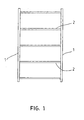
- fig. 1
- is a schematic section of a frame made of two side members and a number of cross members,
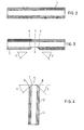
- fig. 2
- is a top view of a section of a side member for a frame,
- fig. 3
- is an illustration of the side member corresponding to the one in fig. 2 with a bar notch,
- fig. 4
- is a top view of a section of a cross member with a cross member notch,
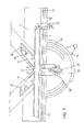
- fig. 5
- is a perspective view of part of a machine according to the invention,
- fig. 6
- shows a stop for a machine according to the invention,
- fig. 7
- is a top view of part of a machine according to the invention with a side member in position and the knife head moved forward during the shearing of a cross member notch,
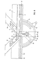
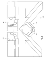
- fig. 8
- is a top view of part of a machine according to the invention with a cross member in position during the shearing operation of a cross member notch,
- fig. 9
- is a perspective view of part of a machine according to the invention with the knife head removed,
- fig. 10
- is a perspective view of two side knives and a nose knife for a machine according to the invention
- fig. 11
- is a perspective view of a nose knife, for a machine according to the invention, and
- fig. 12
- shows the nose knife from another angle.
- As shown in fig. 1 a frame, for example for doors or gates, consists of two
side members 1 and of a number ofcross members 2. Theside members 1 and thecross members 2 are joined in bar joints consisting of a bar notch into the side of aside member 1 and across member notch 4 at the end of across member 2. A side member notch can have aplane bottom 5, which is parallel with a side surface 1' of theside member 1 and twooblique sides 6, which are of equal length and which have two equally large oppositely directed inclines v in relation to thebottom 5. Across member notch 4 consists of aplane end piece 7 at right angles to a side surface 2' in themember 2, and of two equally long oblique sides 8, which have two identical oppositely directed inclines v in relation to thebottom 7. Thebottom 7 and the sides 8 are of such a length that the shape of the cross member fits into the notch. - A
side member notch 3 and across member notch 4 may be produced in one punching or shearing operation with a machine according to the invention. - As shown in the drawing, figs. 5-10, a machine for the production of side member and cross member cuts by shearing comprises a triangular knife head 9 - viewed from above - for two
side knives 10 and anose knife 11. The knife head 9 is movable in the vertical direction in aguide 12. This movement can be effected, for example, by means of of a not shown foot pedal, but it can also be done automatically, for example hydraulically. Theguide 12 is movable in the horizontal direction towards or away from a workpiece to be worked and which rests against arest 13 on a table 14. This movement can be effected by activation of ahandle 15 on a not shown arm, and the setting can be read on ascale 16. This movement can also be automatic, for example hydraulic. - As shown the machine comprises a first set of adjustable guide members which can set the position of the knife head 9 in relation to the
workpiece - These guide members can consist of two
stops 17, which each are displaceably mounted on aguide rail 18, which is mounted on the knife head 9, each along itsown side knife 10 and parallel with them. Thestops 17 have aninside edge 20, which in its mounted position rests against the outside of theside knives 10 and aplane front side 21, which is parallel with therest 13 and can come to rest against theworkpiece - The machine also comprises a second set of of adjustable guide members for the setting of the distance between the bar notches, which are sheared into the side of a
side member 1. - As shown in the drawing the
rest 13 is embodied as a guide rail with a vertical,longitudinal guide list 22 at the rear end. The second set of guide members consists of a number ofstops 23, which are displaceable along therest 13 and can be clamped to it by a knob-head bench screw 24. Eachstop 23 has at its rear end - at the guide list 22 - alower part 25 with a U-shapedopening 26, which can accommodate the lower edge of theguide list 22, and anupper part 27, which is embodied as a fork, which in its mounted position reaches in over the whole width of therest 13. Anarm 28, which can be received in thefork 27, is at one end embodied with a stop 28' against which the end of aworkpiece 1, which is to be processed, can come to rest. At the opposite end thearm 28 is swingably hinged to theupper part 27 by apin 28", so that it can be swung over to a passive position. - As shown in figs. 7 and 8 the
rest 13 is split up into a right-hand part 13' and a left-hand part 13", which off the centre of the knife head 9 are placed at a mutual distance a. The third guide members consists of acatch 29, which can be moved crosswise to the rest 13 in aguide 30, which is mounted on the table 14 in the space a. As shown thecatch 29 can be displaced to adopt a forward working position in which it protrudes a distance forward over thefront edge 31 of the rest 13, and in which it serves as a rest for the end of across member 2 during the punching of across member notch 4. From this position thecatch 29 can be displaced to a retracted, passive position behind the front edge of the rest. The catch can be fixed to the table 14 by means of a clampingarrangement 32. - As shown in fig. 9 there is an
indentation 33 in the table 14 under the set ofknives side knives 10 and thenose knife 11 can therefore in their bottom position be at a level with or slightly lower than the top side of the table 14. In theindentation 33 there is a detachably mounteddolly 34 of a soft material, e.g. of a synthetic material. Thedolly 34 can be supported by and mounted on aplate member 35 screwed to the machine. The result is that a clean cut can be produced in the workpiece to be processed. - The
nose knife 11 can be of the same width as the bottom 5 in across member notch 3. Consequently, there is no need to displace thebar 1 lengthwise along the rest 13 during the shearing of across member notch 3. - The nose knife shown in figs. 11 and 12 with a V-shaped notch is employed for narrow workpieces.
- When a shearing operation is started the
plane front side 21 of theguide members 17 is held at a short distance from the side of the bar to be processed. - In the final phase of the shearing operation the
front side 21 rests against the side of theworkpiece
Claims (7)
- Machine for the production of a bar notch (3) in the side of a side member (1) and a cross member notch (4) at the end of a cross bar member (2) for cross bar assemblies between a side member (1) and a bar (2) in objects of wood, plastics or MDF - medium density fibreboard - and which comprises a knife head (9) for two side knives (10), which can be displaced vertically in a guide (12) down towards and away from a work piece (1) or (2), to be processed, which work piece rests against a rest (13) on a table (14),
characterised by the fact that
the knife head (9) is triangular in a top view and embodied with a nose knife (11) and the guide (12) can be moved in the horizontal direction towards or away from the work piece (1) or (2), and that the machine is embodied with a first set of adjustable guide members (17), which can set the position of the knifehead (9) in the horizontal direction in relation to the workpiece (1) or (2), which is to be processed accurately during the shearing operation, with a second set of adjustable guide members (23) mounted on the rest (13) for the setting of the distance between the bar notches (3), and with a third guide member (29), which can function as an end stop for a cross member in the process of shearing a cross bar notch (4), and that the table (14) is embodied with an indentation (33) which permits the bottom cutting edge of the two side knives (10) and the nose knife (11) in their bottom position to be level with or slightly lower in relation to the top side of the table (14), and that the indentation (33) is fitted with a dolly (34) of a soft material, for example a synthetic material. - Machine according to claim 1
characterised by the fact that
the first set of adjustable guide members consists of two stops (17) which each is displaceably positioned on a guide rail (18) mounted on the knife head (9) each along its own side knife (10) and which can be fixed to a guide rail (18) in a desired position by means of screws (19) which stops (17) have an internal edge (20), which rests against the outer side of a side knife (10) and a plane front side (21), which can come to rest against the workpiece (1) or (2) which is to be processed, and which is parallel with the rest (13). - Machine according to claim 1
characterised by the fact that
the rest (13) is embodied as a guide rail with a longitudinal guide list (22) at the rear end, and that the second set of adjustable guide members consists of a number of stops (23), which can be displaced in the longitudinal direction of the rest (13) and can be fixed to it in a desired position by means of a bench screw (24) with a handle, and that the stop (23) is embodied with a swingable arm (28), which from an active position - in which a stop (28') at the end of the arm can come to rest against the end of the workpiece (1) to be processed - can be swung to a passive position. - Machine according to claim 3
characterised by the fact that
the stop (23) at the rear end at the guide list (22) has a lower part (25) with a U-shaped opening (26) to accommodate the bottom edge of the guide list (22), and an upper part (27) embodied as a fork, which in its mounted position reaches in over the rest (13) and acts as a guide for the arm (28) in the latter's active position, and that the arm (28) is swingably hinged to the upper part (27) at a stud (28"). - Machine according to claim 1
characterised by the fact that
the rest (13) consists of two parts, a right-hand part (13') and a left-hand part (13"), which off the centre of the knife head (9) are placed at a mutual distance (a), and that the third guide members consists of a catch (29), which can be made of square-bar steel and which can be displaced crosswise to the rest (13) in a guide (30) which is mounted on the table (14) in the space (a) from a forward processing position in which the catch (29) projects a distance forward of the front edge (31) of the rest (13), and where it serves as a rest for the end of a bar (2) during the punching of a cross member notch (4), to a retracted passive position, and that the catch (29) can be fixed to the table (14) by means of a clamping arrangement (32). - Machine according to claim 1
characterised by the fact that
the dolly (34) is detachably mounted on a plate (35). - Machine according to claim 1
characterised by the fact that
the nose knife (11) is of the same width as the bottom (5) in a cross member notch (3).
Applications Claiming Priority (2)
| Application Number | Priority Date | Filing Date | Title |
|---|---|---|---|
| DK200001661A DK174105B1 (en) | 2000-11-07 | 2000-11-07 | Process for making a crusher assembly and a machine for carrying out the method |
| DK200001661 | 2000-11-07 |
Publications (3)
| Publication Number | Publication Date |
|---|---|
| EP1205286A2 EP1205286A2 (en) | 2002-05-15 |
| EP1205286A3 EP1205286A3 (en) | 2005-11-09 |
| EP1205286B1 true EP1205286B1 (en) | 2007-09-05 |
Family
ID=8159826
Family Applications (1)
| Application Number | Title | Priority Date | Filing Date |
|---|---|---|---|
| EP00610130A Expired - Lifetime EP1205286B1 (en) | 2000-11-07 | 2000-12-15 | Machine for the production of a bar notch in the side of a side member and a bar notch at the end of a cross member for a bar joint between a side member and a cross member |
Country Status (6)
| Country | Link |
|---|---|
| US (2) | US6941848B2 (en) |
| EP (1) | EP1205286B1 (en) |
| AT (1) | ATE372195T1 (en) |
| DE (1) | DE60036293T2 (en) |
| DK (1) | DK174105B1 (en) |
| ES (1) | ES2292418T3 (en) |
Cited By (1)
| Publication number | Priority date | Publication date | Assignee | Title |
|---|---|---|---|---|
| CN104440463A (en) * | 2014-12-23 | 2015-03-25 | 展彩娜 | Multiple-grinding-head grooving device for curved grooves of plates |
Families Citing this family (5)
| Publication number | Priority date | Publication date | Assignee | Title |
|---|---|---|---|---|
| DK174105B1 (en) * | 2000-11-07 | 2002-06-17 | Dan List As Maskinfabrik | Process for making a crusher assembly and a machine for carrying out the method |
| CN104589420B (en) * | 2014-12-23 | 2016-06-29 | 山东科技大学 | Multi-knife-head sheet material is automatic boring device continuously |
| CN104608219A (en) * | 2015-01-09 | 2015-05-13 | 浙江画之都文化创意股份有限公司 | Wooden box notching machine |
| US9895756B2 (en) * | 2015-05-11 | 2018-02-20 | Paul Eugene Fiala | Flip-down table-saw fence |
| CN113172709B (en) * | 2021-04-30 | 2022-08-16 | 福州福田工艺品有限公司 | Wood plate engraving device and working method thereof |
Family Cites Families (60)
| Publication number | Priority date | Publication date | Assignee | Title |
|---|---|---|---|---|
| US422929A (en) * | 1890-03-11 | Die for shearing fence-pickets | ||
| USRE15496E (en) * | 1922-11-21 | Method of making roofing slabs | ||
| US422517A (en) * | 1890-03-04 | Peters | ||
| US1274605A (en) * | 1914-01-03 | 1918-08-06 | Carrie H Russell | Method of making a plurality of shingles from a singel sheet of material. |
| US1351115A (en) * | 1917-09-29 | 1920-08-31 | Samuel R Parry | Adjustable cutting-knife |
| GB155978A (en) * | 1919-12-02 | 1921-01-06 | William Gardner Thomson | A machine for cutting joints in wood or metal |
| GB148732A (en) * | 1920-04-29 | 1920-08-05 | Emil Witalis Hermansson | Improvements in wooden sash bar making machine |
| US1482776A (en) * | 1921-02-19 | 1924-02-05 | Ruberoid Company | Shingle machine |
| US1548107A (en) * | 1921-03-17 | 1925-08-04 | Ruberoid Co | Shingle-strip machine |
| US1531287A (en) * | 1924-04-21 | 1925-03-31 | Whitney Metal Tool Company | Angle-iron notcher |
| US1665600A (en) * | 1924-11-01 | 1928-04-10 | Barrett Co | Method of cutting shingles |
| US1666204A (en) * | 1926-06-16 | 1928-04-17 | Norman P Harshberger | Shingle |
| US1846635A (en) * | 1927-05-02 | 1932-02-23 | Paraffine Co Inc | Method of cutting shingles |
| FR723340A (en) * | 1930-12-09 | 1932-04-07 | Kodak Pathe | New process for perforating bands |
| US2325311A (en) * | 1942-05-18 | 1943-07-27 | Freeman Co Louis G | Die for bevel cutting |
| US2444706A (en) * | 1944-07-25 | 1948-07-06 | Loew Sigmund | Slide fastener machine |
| US2679869A (en) * | 1952-07-31 | 1954-06-01 | William M Knourek | Machine for forming interlocking mitered joints for muntin structures |
| US3065657A (en) * | 1956-04-16 | 1962-11-27 | Thomas H Thompson | Sheet metal tubing cutter |
| US2837160A (en) * | 1956-08-20 | 1958-06-03 | Robert M Vera | Downspout mitering tool |
| US3097684A (en) * | 1960-01-14 | 1963-07-16 | Le Tarte Company Inc | Method of forming a closed corner in a hollow rectilinear metal workpiece |
| US3277763A (en) * | 1964-04-23 | 1966-10-11 | Peck Stow & Wilcox Co | Notching machine |
| US3627866A (en) * | 1969-06-09 | 1971-12-14 | Synectics Dev Corp | Method of making shaped articles |
| US3664011A (en) * | 1969-08-08 | 1972-05-23 | Jacques Guillon Designers Inc | Method of making a joinery joint |
| SE356244B (en) * | 1971-09-28 | 1973-05-21 | B Storkh | |
| GB1391497A (en) * | 1972-09-27 | 1975-04-23 | Davey S G | Notching machines |
| US4012975A (en) * | 1975-07-31 | 1977-03-22 | Lalone Barry Grant | High speed punching apparatus and tool therefor |
| DE7601264U1 (en) * | 1976-01-19 | 1976-10-14 | Laepple, Rolf, 7067 Pluederhausen | Device for cutting profile strips on a miter or other shaped cutouts |
| US4327618A (en) * | 1977-01-31 | 1982-05-04 | Harvey Menard | Apparatus for cutting a strip of material |
| IT1156914B (en) * | 1978-03-13 | 1987-02-04 | Lavazza Gian Maria | PROCEDURE AND DEVICE FOR CUTTING A PLURALITY OF CONTINUOUS PIECES IN THE SHAPE OF A COMB SHEET |
| JPS5837533Y2 (en) * | 1978-05-10 | 1983-08-24 | 株式会社アマダ | Edge cutting machine |
| US4344342A (en) * | 1980-08-27 | 1982-08-17 | Sam Garvin & Company | Method for the manufacture of washers and the like |
| IN154459B (en) * | 1980-09-12 | 1984-10-27 | Edgar Malcolm Stubbersfield | |
| DK146500C (en) * | 1981-05-27 | 1984-03-26 | Hjortshoej & Poulsen Aps | CUTTING MACHINE, NECESSARY FOR CUTTING FRAME FRAME LAMPS |
| DE8200527U1 (en) * | 1982-01-13 | 1982-07-01 | F.I.M. S.r.l., 40127 Bologna | CORNER SCISSORS |
| US4481848A (en) * | 1982-06-07 | 1984-11-13 | Takeda Machinery Works Company, Ltd. | Corner shear machine |
| US4433600A (en) * | 1982-06-07 | 1984-02-28 | Takeda Machinery Works Company, Ltd. | Workpiece locating device for a corner shear machine |
| US4455904A (en) * | 1982-09-30 | 1984-06-26 | Havner Charles W | Work frame cutting support |
| US4611519A (en) * | 1984-09-13 | 1986-09-16 | Hagerty Lloyd A | Radius corner forming apparatus and method |
| US4643389A (en) * | 1984-12-27 | 1987-02-17 | American Hospital Supply Corporation | Tubing occlusion clip |
| IT1200660B (en) * | 1985-06-28 | 1989-01-27 | Fim Srl | ANGULAR SHEAR AND DEVICE FOR AUTOMATIC PREPARING OF THE SHEET POSITIONING |
| US4638698A (en) * | 1986-02-28 | 1987-01-27 | Prints Plus, Inc. | Drop feed mitering machine |
| US4831910A (en) * | 1986-03-26 | 1989-05-23 | Poulsen Oluf K | Frame list cutting machine and a knife therefor |
| US4693158A (en) * | 1986-04-24 | 1987-09-15 | Price T David | Fence system with a stop mechanism |
| US4907383A (en) * | 1987-04-27 | 1990-03-13 | Winter Amos G Iv | Bowed roof structure, structure panel and method for using same |
| US5052256A (en) * | 1989-04-13 | 1991-10-01 | Morrissey N Richard | Apparatus for cutting shingles |
| US5337641A (en) * | 1992-09-14 | 1994-08-16 | Duginske Mark A | Woodworking machinery jig and fixture system |
| US5273253A (en) * | 1992-12-08 | 1993-12-28 | Rogers Craig L | Fire hose clamp |
| US5740713A (en) * | 1993-12-23 | 1998-04-21 | Korb; Lothar | Notch cutter |
| US5463920A (en) * | 1993-12-23 | 1995-11-07 | Korb; Lothar | Notch cutter and method |
| GB2301135A (en) * | 1995-05-25 | 1996-11-27 | David John Goodman | Plastics window frame joint connection |
| US5720537A (en) * | 1995-07-07 | 1998-02-24 | Heinrich Lutz | Dovetail joint construction |
| JPH0973760A (en) * | 1995-09-07 | 1997-03-18 | Sony Corp | Method for blanking plate stock and base plate of tape cassette |
| US6393685B1 (en) * | 1997-06-10 | 2002-05-28 | The Regents Of The University Of California | Microjoinery methods and devices |
| US5873292A (en) * | 1997-06-26 | 1999-02-23 | Goese; James A. | Holddown bar for power notcher |
| US6112413A (en) * | 1999-03-08 | 2000-09-05 | Frakes; Thomas Wayne | Shingle severing device |
| US6240822B1 (en) * | 1999-07-28 | 2001-06-05 | Ronald L. Musser | Adjustable precision indexing jig |
| US6293177B1 (en) * | 2000-04-20 | 2001-09-25 | Mackenzie George L. | Workpiece positioning device |
| US6283668B1 (en) * | 2000-05-03 | 2001-09-04 | Norek Technical Resources, Inc. | No-slip corner joint |
| DK174105B1 (en) * | 2000-11-07 | 2002-06-17 | Dan List As Maskinfabrik | Process for making a crusher assembly and a machine for carrying out the method |
| US6688197B1 (en) * | 2001-09-24 | 2004-02-10 | Leo L. Niemela | Notch sawing apparatus for dove-tail joints |
-
2000
- 2000-11-07 DK DK200001661A patent/DK174105B1/en not_active IP Right Cessation
- 2000-12-15 AT AT00610130T patent/ATE372195T1/en not_active IP Right Cessation
- 2000-12-15 ES ES00610130T patent/ES2292418T3/en not_active Expired - Lifetime
- 2000-12-15 EP EP00610130A patent/EP1205286B1/en not_active Expired - Lifetime
- 2000-12-15 DE DE60036293T patent/DE60036293T2/en not_active Expired - Fee Related
-
2001
- 2001-01-10 US US09/756,733 patent/US6941848B2/en not_active Expired - Lifetime
-
2002
- 2002-06-07 US US10/163,533 patent/US6675686B2/en not_active Expired - Lifetime
Cited By (1)
| Publication number | Priority date | Publication date | Assignee | Title |
|---|---|---|---|---|
| CN104440463A (en) * | 2014-12-23 | 2015-03-25 | 展彩娜 | Multiple-grinding-head grooving device for curved grooves of plates |
Also Published As
| Publication number | Publication date |
|---|---|
| ES2292418T3 (en) | 2008-03-16 |
| DK200001661A (en) | 2002-05-07 |
| US6675686B2 (en) | 2004-01-13 |
| US20020053269A1 (en) | 2002-05-09 |
| US6941848B2 (en) | 2005-09-13 |
| DE60036293T2 (en) | 2008-06-05 |
| EP1205286A3 (en) | 2005-11-09 |
| US20020148341A1 (en) | 2002-10-17 |
| EP1205286A2 (en) | 2002-05-15 |
| DK174105B1 (en) | 2002-06-17 |
| DE60036293D1 (en) | 2007-10-18 |
| ATE372195T1 (en) | 2007-09-15 |
Similar Documents
| Publication | Publication Date | Title |
|---|---|---|
| CN108430718B (en) | Woodworking table and multifunctional woodworking device | |
| US4694871A (en) | Process for the manufacture of panel-type workpieces with assembly bores, more particularly, made of wood or wood-like material and apparatus for performing the process | |
| CN219151859U (en) | Metal plate planing and laser cutting device and planing and laser cutting machine | |
| US5448819A (en) | Corner cleaning machine and method | |
| EP1205286B1 (en) | Machine for the production of a bar notch in the side of a side member and a bar notch at the end of a cross member for a bar joint between a side member and a cross member | |
| EP1810769A1 (en) | Panel working machine with a saw unit | |
| US4445553A (en) | Apparatus for shaping a wooden workpiece | |
| US20090065096A1 (en) | Moulder | |
| US4455904A (en) | Work frame cutting support | |
| US6899152B2 (en) | Dovetail jig | |
| US5630455A (en) | Groove forming apparatus and method | |
| EP0485485B1 (en) | Corner cutting shear machine and method for forming inside corners in a one-piece article | |
| CA1264336A (en) | Workholder for machine tools | |
| DE19601331C1 (en) | Machine tool for flat wooden workpiece | |
| EP2017046B1 (en) | Portable planing machine | |
| EP1297923B2 (en) | Machining unit for deburring of corner joints of window or door frames of welded plastic profiles | |
| EP1038645B1 (en) | Method and apparatus for working glazing beads, preferably for making mitre cuts for window frames, in particular with acute or obtuse angles at the frame corners | |
| GB2247430A (en) | Adjustable template for cutting letter-box slots | |
| DE102006019113B4 (en) | Apparatus and method with a laser machined workpieces of wood or similar material to protect against splintering | |
| EP1711306B1 (en) | Shaping device, particularly for shaping substantially elongated elements | |
| RU45960U1 (en) | HINGE MILLING MACHINE | |
| EP1613452B1 (en) | Veneer slicing machine | |
| CN213858211U (en) | Novel multifunctional profile engraving and milling machine | |
| EP0798074B1 (en) | Sawing device for machining the front end of profiled rods | |
| JPS5928808Y2 (en) | Workpiece clamping device for woodworking processing machines |
Legal Events
| Date | Code | Title | Description |
|---|---|---|---|
| PUAI | Public reference made under article 153(3) epc to a published international application that has entered the european phase |
Free format text: ORIGINAL CODE: 0009012 |
|
| AK | Designated contracting states |
Kind code of ref document: A2 Designated state(s): AT BE CH CY DE DK ES FI FR GB GR IE IT LI LU MC NL PT SE TR |
|
| AX | Request for extension of the european patent |
Free format text: AL;LT;LV;MK;RO;SI |
|
| PUAL | Search report despatched |
Free format text: ORIGINAL CODE: 0009013 |
|
| AK | Designated contracting states |
Kind code of ref document: A3 Designated state(s): AT BE CH CY DE DK ES FI FR GB GR IE IT LI LU MC NL PT SE TR |
|
| AX | Request for extension of the european patent |
Extension state: AL LT LV MK RO SI |
|
| 17P | Request for examination filed |
Effective date: 20051208 |
|
| AKX | Designation fees paid |
Designated state(s): AT BE CH CY DE DK ES FI FR GB GR IE IT LI LU MC NL PT SE TR |
|
| GRAP | Despatch of communication of intention to grant a patent |
Free format text: ORIGINAL CODE: EPIDOSNIGR1 |
|
| RTI1 | Title (correction) |
Free format text: MACHINE FOR THE PRODUCTION OF A BAR NOTCH IN THE SIDE OF A SIDE MEMBER AND A BAR NOTCH AT THE END OF A CROSS MEMBER FOR A BAR JOINT BETWEEN A SIDE MEMBER AND A CROSS MEMBER |
|
| GRAS | Grant fee paid |
Free format text: ORIGINAL CODE: EPIDOSNIGR3 |
|
| GRAA | (expected) grant |
Free format text: ORIGINAL CODE: 0009210 |
|
| AK | Designated contracting states |
Kind code of ref document: B1 Designated state(s): AT BE CH CY DE DK ES FI FR GB GR IE IT LI LU MC NL PT SE TR |
|
| REG | Reference to a national code |
Ref country code: GB Ref legal event code: FG4D |
|
| REG | Reference to a national code |
Ref country code: CH Ref legal event code: EP |
|
| REF | Corresponds to: |
Ref document number: 60036293 Country of ref document: DE Date of ref document: 20071018 Kind code of ref document: P |
|
| REG | Reference to a national code |
Ref country code: IE Ref legal event code: FG4D |
|
| REG | Reference to a national code |
Ref country code: SE Ref legal event code: TRGR |
|
| PG25 | Lapsed in a contracting state [announced via postgrant information from national office to epo] |
Ref country code: FI Free format text: LAPSE BECAUSE OF FAILURE TO SUBMIT A TRANSLATION OF THE DESCRIPTION OR TO PAY THE FEE WITHIN THE PRESCRIBED TIME-LIMIT Effective date: 20070905 |
|
| PGFP | Annual fee paid to national office [announced via postgrant information from national office to epo] |
Ref country code: NL Payment date: 20071221 Year of fee payment: 8 |
|
| PG25 | Lapsed in a contracting state [announced via postgrant information from national office to epo] |
Ref country code: CH Free format text: LAPSE BECAUSE OF FAILURE TO SUBMIT A TRANSLATION OF THE DESCRIPTION OR TO PAY THE FEE WITHIN THE PRESCRIBED TIME-LIMIT Effective date: 20070905 Ref country code: LI Free format text: LAPSE BECAUSE OF FAILURE TO SUBMIT A TRANSLATION OF THE DESCRIPTION OR TO PAY THE FEE WITHIN THE PRESCRIBED TIME-LIMIT Effective date: 20070905 Ref country code: AT Free format text: LAPSE BECAUSE OF FAILURE TO SUBMIT A TRANSLATION OF THE DESCRIPTION OR TO PAY THE FEE WITHIN THE PRESCRIBED TIME-LIMIT Effective date: 20070905 |
|
| REG | Reference to a national code |
Ref country code: ES Ref legal event code: FG2A Ref document number: 2292418 Country of ref document: ES Kind code of ref document: T3 |
|
| PGFP | Annual fee paid to national office [announced via postgrant information from national office to epo] |
Ref country code: SE Payment date: 20071212 Year of fee payment: 8 Ref country code: BE Payment date: 20071108 Year of fee payment: 8 |
|
| REG | Reference to a national code |
Ref country code: CH Ref legal event code: PL |
|
| PG25 | Lapsed in a contracting state [announced via postgrant information from national office to epo] |
Ref country code: GR Free format text: LAPSE BECAUSE OF FAILURE TO SUBMIT A TRANSLATION OF THE DESCRIPTION OR TO PAY THE FEE WITHIN THE PRESCRIBED TIME-LIMIT Effective date: 20071206 |
|
| PGFP | Annual fee paid to national office [announced via postgrant information from national office to epo] |
Ref country code: ES Payment date: 20071227 Year of fee payment: 8 Ref country code: FR Payment date: 20071128 Year of fee payment: 8 |
|
| EN | Fr: translation not filed | ||
| PG25 | Lapsed in a contracting state [announced via postgrant information from national office to epo] |
Ref country code: PT Free format text: LAPSE BECAUSE OF FAILURE TO SUBMIT A TRANSLATION OF THE DESCRIPTION OR TO PAY THE FEE WITHIN THE PRESCRIBED TIME-LIMIT Effective date: 20080206 |
|
| PGFP | Annual fee paid to national office [announced via postgrant information from national office to epo] |
Ref country code: TR Payment date: 20071121 Year of fee payment: 8 |
|
| PLBE | No opposition filed within time limit |
Free format text: ORIGINAL CODE: 0009261 |
|
| STAA | Information on the status of an ep patent application or granted ep patent |
Free format text: STATUS: NO OPPOSITION FILED WITHIN TIME LIMIT |
|
| PG25 | Lapsed in a contracting state [announced via postgrant information from national office to epo] |
Ref country code: DK Free format text: LAPSE BECAUSE OF FAILURE TO SUBMIT A TRANSLATION OF THE DESCRIPTION OR TO PAY THE FEE WITHIN THE PRESCRIBED TIME-LIMIT Effective date: 20070905 Ref country code: MC Free format text: LAPSE BECAUSE OF NON-PAYMENT OF DUE FEES Effective date: 20071231 |
|
| PGFP | Annual fee paid to national office [announced via postgrant information from national office to epo] |
Ref country code: DE Payment date: 20080226 Year of fee payment: 8 |
|
| ET | Fr: translation filed | ||
| REG | Reference to a national code |
Ref country code: FR Ref legal event code: EERR Free format text: CORRECTION DE BOPI 08/18 - BREVETS EUROPEENS DONT LA TRADUCTION N A PAS ETE REMISE A L INPI. IL Y A LIEU DE SUPPRIMER : LA MENTION DE LA NON-REMISE. LA REMISE DE LA TRADITION EST PUBLIEE DANS LE PRESENT BOPI. |
|
| 26N | No opposition filed |
Effective date: 20080606 |
|
| PG25 | Lapsed in a contracting state [announced via postgrant information from national office to epo] |
Ref country code: FR Free format text: LAPSE BECAUSE OF FAILURE TO SUBMIT A TRANSLATION OF THE DESCRIPTION OR TO PAY THE FEE WITHIN THE PRESCRIBED TIME-LIMIT Effective date: 20080502 |
|
| BERE | Be: lapsed |
Owner name: DAN-LIST A/S MASKINFABRIK Effective date: 20081231 |
|
| PG25 | Lapsed in a contracting state [announced via postgrant information from national office to epo] |
Ref country code: CY Free format text: LAPSE BECAUSE OF FAILURE TO SUBMIT A TRANSLATION OF THE DESCRIPTION OR TO PAY THE FEE WITHIN THE PRESCRIBED TIME-LIMIT Effective date: 20070905 |
|
| EUG | Se: european patent has lapsed | ||
| PG25 | Lapsed in a contracting state [announced via postgrant information from national office to epo] |
Ref country code: LU Free format text: LAPSE BECAUSE OF NON-PAYMENT OF DUE FEES Effective date: 20071215 |
|
| NLV4 | Nl: lapsed or anulled due to non-payment of the annual fee |
Effective date: 20090701 |
|
| PG25 | Lapsed in a contracting state [announced via postgrant information from national office to epo] |
Ref country code: BE Free format text: LAPSE BECAUSE OF NON-PAYMENT OF DUE FEES Effective date: 20081231 |
|
| REG | Reference to a national code |
Ref country code: FR Ref legal event code: ST Effective date: 20090831 |
|
| PG25 | Lapsed in a contracting state [announced via postgrant information from national office to epo] |
Ref country code: DE Free format text: LAPSE BECAUSE OF NON-PAYMENT OF DUE FEES Effective date: 20090701 |
|
| PG25 | Lapsed in a contracting state [announced via postgrant information from national office to epo] |
Ref country code: NL Free format text: LAPSE BECAUSE OF NON-PAYMENT OF DUE FEES Effective date: 20090701 |
|
| REG | Reference to a national code |
Ref country code: ES Ref legal event code: FD2A Effective date: 20081216 |
|
| PG25 | Lapsed in a contracting state [announced via postgrant information from national office to epo] |
Ref country code: FR Free format text: LAPSE BECAUSE OF NON-PAYMENT OF DUE FEES Effective date: 20081231 Ref country code: ES Free format text: LAPSE BECAUSE OF NON-PAYMENT OF DUE FEES Effective date: 20081216 |
|
| PG25 | Lapsed in a contracting state [announced via postgrant information from national office to epo] |
Ref country code: SE Free format text: LAPSE BECAUSE OF NON-PAYMENT OF DUE FEES Effective date: 20081216 |
|
| PG25 | Lapsed in a contracting state [announced via postgrant information from national office to epo] |
Ref country code: IT Free format text: LAPSE BECAUSE OF NON-PAYMENT OF DUE FEES Effective date: 20071231 |
|
| PG25 | Lapsed in a contracting state [announced via postgrant information from national office to epo] |
Ref country code: TR Free format text: LAPSE BECAUSE OF NON-PAYMENT OF DUE FEES Effective date: 20081215 |
|
| PGFP | Annual fee paid to national office [announced via postgrant information from national office to epo] |
Ref country code: IE Payment date: 20181219 Year of fee payment: 19 |
|
| PGFP | Annual fee paid to national office [announced via postgrant information from national office to epo] |
Ref country code: GB Payment date: 20181217 Year of fee payment: 19 |
|
| GBPC | Gb: european patent ceased through non-payment of renewal fee |
Effective date: 20191215 |
|
| PG25 | Lapsed in a contracting state [announced via postgrant information from national office to epo] |
Ref country code: IE Free format text: LAPSE BECAUSE OF NON-PAYMENT OF DUE FEES Effective date: 20191215 Ref country code: GB Free format text: LAPSE BECAUSE OF NON-PAYMENT OF DUE FEES Effective date: 20191215 |