EP1205001B1 - A fuel cell gas separator - Google Patents
A fuel cell gas separator Download PDFInfo
- Publication number
- EP1205001B1 EP1205001B1 EP00930877A EP00930877A EP1205001B1 EP 1205001 B1 EP1205001 B1 EP 1205001B1 EP 00930877 A EP00930877 A EP 00930877A EP 00930877 A EP00930877 A EP 00930877A EP 1205001 B1 EP1205001 B1 EP 1205001B1
- Authority
- EP
- European Patent Office
- Prior art keywords
- copper
- layer
- fuel cell
- gas separator
- cell stack
- Prior art date
- Legal status (The legal status is an assumption and is not a legal conclusion. Google has not performed a legal analysis and makes no representation as to the accuracy of the status listed.)
- Expired - Lifetime
Links
- 239000000446 fuel Substances 0.000 title claims abstract description 131
- 239000010410 layer Substances 0.000 claims abstract description 132
- 239000010949 copper Substances 0.000 claims abstract description 129
- 229910052802 copper Inorganic materials 0.000 claims abstract description 126
- RYGMFSIKBFXOCR-UHFFFAOYSA-N Copper Chemical compound [Cu] RYGMFSIKBFXOCR-UHFFFAOYSA-N 0.000 claims abstract description 124
- 229910045601 alloy Inorganic materials 0.000 claims abstract description 47
- 239000000956 alloy Substances 0.000 claims abstract description 47
- XAGFODPZIPBFFR-UHFFFAOYSA-N aluminium Chemical compound [Al] XAGFODPZIPBFFR-UHFFFAOYSA-N 0.000 claims abstract description 31
- 239000000463 material Substances 0.000 claims abstract description 30
- 230000003647 oxidation Effects 0.000 claims abstract description 29
- 238000007254 oxidation reaction Methods 0.000 claims abstract description 29
- 229910000831 Steel Inorganic materials 0.000 claims abstract description 28
- 239000010959 steel Substances 0.000 claims abstract description 28
- 239000011241 protective layer Substances 0.000 claims abstract description 23
- 239000011888 foil Substances 0.000 claims abstract description 15
- PNEYBMLMFCGWSK-UHFFFAOYSA-N aluminium oxide Inorganic materials [O-2].[O-2].[O-2].[Al+3].[Al+3] PNEYBMLMFCGWSK-UHFFFAOYSA-N 0.000 claims description 36
- 229910052759 nickel Inorganic materials 0.000 claims description 27
- 229910052782 aluminium Inorganic materials 0.000 claims description 25
- 238000000576 coating method Methods 0.000 claims description 20
- 229910052751 metal Inorganic materials 0.000 claims description 20
- 239000002184 metal Substances 0.000 claims description 20
- 239000007787 solid Substances 0.000 claims description 18
- 239000011248 coating agent Substances 0.000 claims description 17
- 239000004411 aluminium Substances 0.000 claims description 16
- 229910052593 corundum Inorganic materials 0.000 claims description 12
- 239000003792 electrolyte Substances 0.000 claims description 12
- 229910001845 yogo sapphire Inorganic materials 0.000 claims description 12
- 229910052709 silver Inorganic materials 0.000 claims description 11
- 230000004888 barrier function Effects 0.000 claims description 10
- 239000000758 substrate Substances 0.000 claims description 8
- 150000002739 metals Chemical class 0.000 claims description 7
- 238000005275 alloying Methods 0.000 claims description 6
- 239000002344 surface layer Substances 0.000 claims description 6
- 229910052715 tantalum Inorganic materials 0.000 claims description 4
- 229910052721 tungsten Inorganic materials 0.000 claims description 4
- 229910052742 iron Inorganic materials 0.000 claims description 3
- 229910000510 noble metal Inorganic materials 0.000 claims description 3
- 229910052718 tin Inorganic materials 0.000 claims description 3
- 229910052790 beryllium Inorganic materials 0.000 claims description 2
- 229910052737 gold Inorganic materials 0.000 claims description 2
- 229910052745 lead Inorganic materials 0.000 claims description 2
- 229910052748 manganese Inorganic materials 0.000 claims description 2
- 229910052758 niobium Inorganic materials 0.000 claims description 2
- 229910052698 phosphorus Inorganic materials 0.000 claims description 2
- 229910052710 silicon Inorganic materials 0.000 claims description 2
- 229910052725 zinc Inorganic materials 0.000 claims description 2
- 239000007789 gas Substances 0.000 description 106
- PXHVJJICTQNCMI-UHFFFAOYSA-N Nickel Chemical compound [Ni] PXHVJJICTQNCMI-UHFFFAOYSA-N 0.000 description 53
- MCMNRKCIXSYSNV-UHFFFAOYSA-N Zirconium dioxide Chemical compound O=[Zr]=O MCMNRKCIXSYSNV-UHFFFAOYSA-N 0.000 description 16
- BASFCYQUMIYNBI-UHFFFAOYSA-N platinum Chemical compound [Pt] BASFCYQUMIYNBI-UHFFFAOYSA-N 0.000 description 13
- QVGXLLKOCUKJST-UHFFFAOYSA-N atomic oxygen Chemical compound [O] QVGXLLKOCUKJST-UHFFFAOYSA-N 0.000 description 12
- 239000001301 oxygen Substances 0.000 description 12
- 229910052760 oxygen Inorganic materials 0.000 description 12
- IJGRMHOSHXDMSA-UHFFFAOYSA-N Atomic nitrogen Chemical compound N#N IJGRMHOSHXDMSA-UHFFFAOYSA-N 0.000 description 10
- 239000011651 chromium Substances 0.000 description 10
- VYZAMTAEIAYCRO-UHFFFAOYSA-N Chromium Chemical compound [Cr] VYZAMTAEIAYCRO-UHFFFAOYSA-N 0.000 description 9
- BQCADISMDOOEFD-UHFFFAOYSA-N Silver Chemical compound [Ag] BQCADISMDOOEFD-UHFFFAOYSA-N 0.000 description 9
- 229910052804 chromium Inorganic materials 0.000 description 9
- 239000002737 fuel gas Substances 0.000 description 9
- 239000004332 silver Substances 0.000 description 9
- VNWKTOKETHGBQD-UHFFFAOYSA-N methane Chemical compound C VNWKTOKETHGBQD-UHFFFAOYSA-N 0.000 description 8
- 238000000034 method Methods 0.000 description 7
- 238000012360 testing method Methods 0.000 description 7
- 229910052697 platinum Inorganic materials 0.000 description 6
- 239000011195 cermet Substances 0.000 description 5
- 229910052757 nitrogen Inorganic materials 0.000 description 5
- 238000012546 transfer Methods 0.000 description 5
- 238000000429 assembly Methods 0.000 description 4
- 230000000712 assembly Effects 0.000 description 4
- 230000005611 electricity Effects 0.000 description 4
- 239000001257 hydrogen Substances 0.000 description 4
- 229910052739 hydrogen Inorganic materials 0.000 description 4
- 229910000881 Cu alloy Inorganic materials 0.000 description 3
- UFHFLCQGNIYNRP-UHFFFAOYSA-N Hydrogen Chemical compound [H][H] UFHFLCQGNIYNRP-UHFFFAOYSA-N 0.000 description 3
- 238000011109 contamination Methods 0.000 description 3
- 238000010790 dilution Methods 0.000 description 3
- 239000012895 dilution Substances 0.000 description 3
- 239000011253 protective coating Substances 0.000 description 3
- 229910001220 stainless steel Inorganic materials 0.000 description 3
- BQENXCOZCUHKRE-UHFFFAOYSA-N [La+3].[La+3].[O-][Mn]([O-])=O.[O-][Mn]([O-])=O.[O-][Mn]([O-])=O Chemical compound [La+3].[La+3].[O-][Mn]([O-])=O.[O-][Mn]([O-])=O.[O-][Mn]([O-])=O BQENXCOZCUHKRE-UHFFFAOYSA-N 0.000 description 2
- 239000010405 anode material Substances 0.000 description 2
- 229910052799 carbon Inorganic materials 0.000 description 2
- 239000003054 catalyst Substances 0.000 description 2
- 230000003197 catalytic effect Effects 0.000 description 2
- 239000000919 ceramic Substances 0.000 description 2
- 239000010416 ion conductor Substances 0.000 description 2
- 229910001092 metal group alloy Inorganic materials 0.000 description 2
- 238000012986 modification Methods 0.000 description 2
- 230000004048 modification Effects 0.000 description 2
- 239000007800 oxidant agent Substances 0.000 description 2
- 230000001590 oxidative effect Effects 0.000 description 2
- 231100000572 poisoning Toxicity 0.000 description 2
- 230000000607 poisoning effect Effects 0.000 description 2
- 239000002243 precursor Substances 0.000 description 2
- 239000010935 stainless steel Substances 0.000 description 2
- 229910052712 strontium Inorganic materials 0.000 description 2
- CIOAGBVUUVVLOB-UHFFFAOYSA-N strontium atom Chemical compound [Sr] CIOAGBVUUVVLOB-UHFFFAOYSA-N 0.000 description 2
- 238000011282 treatment Methods 0.000 description 2
- OTMSDBZUPAUEDD-UHFFFAOYSA-N Ethane Chemical compound CC OTMSDBZUPAUEDD-UHFFFAOYSA-N 0.000 description 1
- 239000006057 Non-nutritive feed additive Substances 0.000 description 1
- 239000000654 additive Substances 0.000 description 1
- 238000013459 approach Methods 0.000 description 1
- 238000003491 array Methods 0.000 description 1
- 238000006243 chemical reaction Methods 0.000 description 1
- 238000002485 combustion reaction Methods 0.000 description 1
- 150000001875 compounds Chemical class 0.000 description 1
- 239000004020 conductor Substances 0.000 description 1
- 238000010276 construction Methods 0.000 description 1
- 238000004320 controlled atmosphere Methods 0.000 description 1
- 230000000593 degrading effect Effects 0.000 description 1
- 230000002939 deleterious effect Effects 0.000 description 1
- 238000000151 deposition Methods 0.000 description 1
- 230000008021 deposition Effects 0.000 description 1
- 238000005137 deposition process Methods 0.000 description 1
- 238000009792 diffusion process Methods 0.000 description 1
- 238000007865 diluting Methods 0.000 description 1
- 238000007598 dipping method Methods 0.000 description 1
- 238000010891 electric arc Methods 0.000 description 1
- 239000012777 electrically insulating material Substances 0.000 description 1
- 239000011532 electronic conductor Substances 0.000 description 1
- 238000009713 electroplating Methods 0.000 description 1
- 230000007717 exclusion Effects 0.000 description 1
- 238000002474 experimental method Methods 0.000 description 1
- 239000011521 glass Substances 0.000 description 1
- 238000010438 heat treatment Methods 0.000 description 1
- 229930195733 hydrocarbon Natural products 0.000 description 1
- 150000002430 hydrocarbons Chemical class 0.000 description 1
- 150000002431 hydrogen Chemical class 0.000 description 1
- 239000011261 inert gas Substances 0.000 description 1
- 238000002844 melting Methods 0.000 description 1
- 230000008018 melting Effects 0.000 description 1
- 150000001247 metal acetylides Chemical class 0.000 description 1
- 239000002574 poison Substances 0.000 description 1
- 231100000614 poison Toxicity 0.000 description 1
- 238000010926 purge Methods 0.000 description 1
- 238000002407 reforming Methods 0.000 description 1
- 238000007650 screen-printing Methods 0.000 description 1
- 238000007789 sealing Methods 0.000 description 1
- 229910052596 spinel Inorganic materials 0.000 description 1
- 239000011029 spinel Substances 0.000 description 1
- 238000005507 spraying Methods 0.000 description 1
- 238000004544 sputter deposition Methods 0.000 description 1
- GUVRBAGPIYLISA-UHFFFAOYSA-N tantalum atom Chemical compound [Ta] GUVRBAGPIYLISA-UHFFFAOYSA-N 0.000 description 1
- 231100000331 toxic Toxicity 0.000 description 1
- 230000002588 toxic effect Effects 0.000 description 1
- WFKWXMTUELFFGS-UHFFFAOYSA-N tungsten Chemical compound [W] WFKWXMTUELFFGS-UHFFFAOYSA-N 0.000 description 1
- 239000010937 tungsten Substances 0.000 description 1
Images

Classifications
-
- H—ELECTRICITY
- H01—ELECTRIC ELEMENTS
- H01M—PROCESSES OR MEANS, e.g. BATTERIES, FOR THE DIRECT CONVERSION OF CHEMICAL ENERGY INTO ELECTRICAL ENERGY
- H01M8/00—Fuel cells; Manufacture thereof
- H01M8/02—Details
- H01M8/0202—Collectors; Separators, e.g. bipolar separators; Interconnectors
- H01M8/0204—Non-porous and characterised by the material
- H01M8/0206—Metals or alloys
- H01M8/0208—Alloys
- H01M8/021—Alloys based on iron
-
- H—ELECTRICITY
- H01—ELECTRIC ELEMENTS
- H01M—PROCESSES OR MEANS, e.g. BATTERIES, FOR THE DIRECT CONVERSION OF CHEMICAL ENERGY INTO ELECTRICAL ENERGY
- H01M8/00—Fuel cells; Manufacture thereof
- H01M8/10—Fuel cells with solid electrolytes
- H01M8/12—Fuel cells with solid electrolytes operating at high temperature, e.g. with stabilised ZrO2 electrolyte
- H01M2008/1293—Fuel cells with solid oxide electrolytes
-
- H—ELECTRICITY
- H01—ELECTRIC ELEMENTS
- H01M—PROCESSES OR MEANS, e.g. BATTERIES, FOR THE DIRECT CONVERSION OF CHEMICAL ENERGY INTO ELECTRICAL ENERGY
- H01M2300/00—Electrolytes
- H01M2300/0017—Non-aqueous electrolytes
- H01M2300/0065—Solid electrolytes
- H01M2300/0068—Solid electrolytes inorganic
- H01M2300/0071—Oxides
- H01M2300/0074—Ion conductive at high temperature
-
- H—ELECTRICITY
- H01—ELECTRIC ELEMENTS
- H01M—PROCESSES OR MEANS, e.g. BATTERIES, FOR THE DIRECT CONVERSION OF CHEMICAL ENERGY INTO ELECTRICAL ENERGY
- H01M8/00—Fuel cells; Manufacture thereof
- H01M8/02—Details
- H01M8/0202—Collectors; Separators, e.g. bipolar separators; Interconnectors
- H01M8/0204—Non-porous and characterised by the material
- H01M8/0223—Composites
- H01M8/0228—Composites in the form of layered or coated products
-
- Y—GENERAL TAGGING OF NEW TECHNOLOGICAL DEVELOPMENTS; GENERAL TAGGING OF CROSS-SECTIONAL TECHNOLOGIES SPANNING OVER SEVERAL SECTIONS OF THE IPC; TECHNICAL SUBJECTS COVERED BY FORMER USPC CROSS-REFERENCE ART COLLECTIONS [XRACs] AND DIGESTS
- Y02—TECHNOLOGIES OR APPLICATIONS FOR MITIGATION OR ADAPTATION AGAINST CLIMATE CHANGE
- Y02E—REDUCTION OF GREENHOUSE GAS [GHG] EMISSIONS, RELATED TO ENERGY GENERATION, TRANSMISSION OR DISTRIBUTION
- Y02E60/00—Enabling technologies; Technologies with a potential or indirect contribution to GHG emissions mitigation
- Y02E60/30—Hydrogen technology
- Y02E60/50—Fuel cells
Definitions
- the present invention relates to solid oxide fuel cells and is particularly concerned with a planar fuel cell stack having gas separators between adjacent solid oxide fuel cells.
- a gas separator in planar fuel cell assemblies is to keep the oxygen containing gas supplied to the cathode side of one fuel cell separate from the fuel gas supplied to the anode side of an adjacent fuel cell and to conduct heat generated in the fuel cells away from the fuel cells.
- the gas separator may also conduct electricity generated in the fuel cells away from the fuel cells, but this function may alternatively be performed by a separate member between each fuel cell and the gas separator.
- Sophisticated ceramics for use in fuel cell gas separators have been developed which are electrically conductive, but these suffer from a relatively high fragility, low thermal conductivity and high cost.
- Special metallic alloys have also been developed, but it has proved difficult to avoid the various materials of the fuel cell assembly and the interfaces between them degrading or changing substantially through the life of the fuel cell, particularly insofar as their electrical conductivity is concerned, because of the tendency of different materials to chemically interact at the high temperatures which are required for efficient operation of a solid oxide fuel cell.
- most metallic gas separators contain substantial quantities of the element chromium which is used to impart oxidation resistance to the metal as well as other properties.
- the present invention particularly concerns a planar fuel cell stack including at least two planar solid oxide fuel cells each having a layer of solid oxide electrolyte, an anode layer on one side of the electrolyte layer and a cathode layer on the other side of the electrolyte layer, and a gas separator member between the at least two fuel cells, wherein the gas separator member has an anode side and a cathode side and comprises a layer of copper and a layer of oxidation-resistant material on the cathode side of the layer of copper.
- Copper has a sufficient vapour pressure at the operating temperature of at least 750°C of a solid oxide fuel cell that copper vapour may contaminate the active surface of the anode layer of the fuel cell.
- the fuel gas is hydrogen
- the anode layer is commonly of a nickel material and it has been proposed to use the nickel in the anode as a catalyst for reforming methane in the fuel gas to hydrogen.
- the copper vapour has been found to interfere strongly with this catalytic efficiency of the nickel.
- the planar fuel cell stack of the present invention is accordingly characterised by the layer of copper of the gas separator member being a layer of copper or of copper-based alloy containing at least 50 wt% Cu and by the gas separator member comprising a protective layer on the anode side of the copper or copper-based alloy layer to prevent Cu vapour escaping from the anode side of the gas separator member at the operating temperature of the stack.
- Copper has a thermal conductivity which is approximately fourteen times higher than that of typical heat resistant steels, so that considerably less copper may be required to provide a desired heat transfer rate.
- a heat resistant steel gas separator requiring a 4 mm thickness to achieve the required heat transfer rate may be replaced by a gas separator in accordance with the invention having a copper layer thickness of about 0.3 mm. This combined with the substantially reduced cost of copper over the specialist heat resistant steels can greatly reduce the cost and mass of a solid oxide fuel cell stack.
- the layer of copper preferably has a thickness in the range 0.25 mm to 1 mm, more preferably 0.4 mm to 0.7 mm. At thicknesses less than 0.3 mm, it is unlikely that the copper layer will have sufficient bulk to provide the desired thermal transfer at normal solid oxide fuel cell power densities. However, at lower power densities, thinner copper layers may be adequate, for example 0.1 mm or less. Thicknesses greater than about 0.7 mm are unnecessary for pure copper.
- the copper may be alloyed with other elements up to a maximum of 50 wt%, preferably up to 20 wt% of the other elements, in which case a thickness greater than 1 mm, for example up to 4 mm, may be required to provide the desired thermal transfer. Possible alloying elements include Al, Ni, Zn, Sn, Fe, Be, Ag, Au, Mn, Si, P, and Pb, singly or in combinations of two or more.
- a major advantage of alloying the copper in the copper layer with aluminium is that it may form the layer of oxidation-resistant material on the cathode side automatically on being exposed to an oxygen containing gas at elevated temperature, for example in use of the fuel cell gas separator, and in one embodiment the layer of copper or copper-based alloy of the gas separator member is formed of aluminium bronze, the layer of oxidation resistant material is of alumina on the aluminium bronze and the protective layer is of alumina on the aluminium bronze.
- Aluminium bronze comprises copper with at least 4 wt%, more usually at least 5 wt% Al.
- the ability of the aluminium bronze to form an oxidation resistant layer of Al 2 O 3 , and therefore the oxidation resistance of the gas separator member, is very much greater at 5 wt% Al than at 4 wt% Al, but does not increase greatly with further increases in aluminium content.
- Aluminium bronzes have been made with 14 wt% Al, or more, but generally they will have no more than 10 wt% Al.
- processing aids and other additives such as Fe, Sn and other elements in aluminium bronzes is well known.
- the aluminium bronze may be pretreated by heating to at least 650°C, possibly at least 750°C, in air or other oxygen containing gas to form the Al 2 O 3 layers on the cathode and anode sides of the gas separator member, but preferably, as noted above, the oxidation resistant layer is formed in use of the gas separator member.
- Aluminium bronze is considerably less thermally conductive than pure copper, so that greater thicknesses than 0.7 mm may be required for the gas separator member, for example up to 2 mm to provide the desired heat transfer at normal power densities.
- the layer of oxidation resistant material on the cathode side of the gas separator, or a precursor of said layer may be applied to the layer of copper or copper-based alloy, or vice versa.
- the prime function of the layer of oxidation-resistant material is to prevent access of the oxygen containing gas on the cathode side of the fuel cell to the copper or copper-based alloy layer, it need not be a thick layer, for example, in the range 50 to 1000 microns, preferably up to 200 microns, more preferably up to 100 microns, depending upon the type of layer.
- the layer of oxidation-resistant material may take any of a variety of forms, such as a foil which overlies the cathode side of the copper or copper-based alloy arid which, for example, is wrapped over or otherwise attached to it to prevent access of the oxygen containing gas, a coating, or a substrate onto which the copper or copper-based alloy layer is coated.
- the copper or copper-based alloy could be coated onto a substrate layer of oxidation resistant material by sputtering or any other suitable coating technique.
- the preferred foil or substrate material is heat resistant steel, which may itself be coated with alumina on the cathode side or be a self-aluminising heat resistant steel to prevent chromium gas escaping and poisoning the cathode in use of the gas separator.
- a self-aluminising heat resistant steel contains at least 4 wt% A1 and forms an alumina surface layer on being exposed to an oxidising atmosphere at elevated temperature.
- the copper or copper-based alloy layer has a coating of the oxidation-resistant material
- this or a precursor may be applied by vapour deposition or by any of a variety of known processes.
- the oxidation resistant layer may itself comprise plural layers to provide the desired properties. Suitable coating materials include Al, Al 2 O 3 and ZrO 2 .
- the oxidation resistant material coating may comprise Al 2 O 3 applied to the layer of copper or copper-based alloy as an alumina coating or as an aluminium coating which is subsequently oxidised.
- Aluminium may be applied to the copper or alloy surface by a suitable metal spraying technique such as combustion metallising, a low or high velocity oxy-fuel process, an electric arc process, a plasma flame process, by any other vapour deposition process, or even by electro plating or hot dipping.
- the aluminium coating may then be oxidised to provide the alumina layer, but preferably the aluminium is first permitted to diffuse into the copper or alloy surface layer by reacting it at elevated temperature, preferably above the melting temperature of the aluminium, in a controlled atmosphere of an inert gas, a reducing atmosphere or possibly even an oxidising atmosphere. Diffusion is preferably continued until there is no continuous Al layer on the copper or alloy surface, but with at least 5 wt% Al at the exposed surface which is then oxidised to form a continuous alumina layer.
- the protective layer on the anode side may comprise heat resistant steel or alumina as described above and, for example, the copper or copper-based alloy layer may be wrapped entirely in the heat resistant steel foil so that only the superior thermal conductivity properties of the copper or alloy are utilised.
- a heat resistant steel protective layer on the anode side may have a thickness as described above, preferably in the range 50 - 100 ⁇ m.
- An Al 2 O 3 protective layer may have a thickness as small as 1 - 3 ⁇ m, but greater thicknesses as described above may be acceptable.
- the protective layer on the anode side may comprise plural layers.
- a metal barrier layer of any one of W, Ta, or Nb or alloys of one or more of these metals which do not dissolve into the copper may be provided on the copper or copper-based alloy layer, followed by an intermediate layer of Ag plus an outer barrier layer of Ni, a noble metal except Ag or an alloy of one or more of these metals.
- the metal barrier layer acts to prevent the Cu vapour escaping to poison the Ni-containing anode.
- W, Ta and Nb may oxidize to their oxides at the relatively high operating temperatures of a solid oxide fuel cell even in the relatively low oxygen partial pressures on the fuel side of the fuel cell and/or react with hydrocarbons or CO 2 to form carbides, and the Ag layer is provided to alleviate this.
- the metal or metals of the metal barrier layer and of the outer barrier layer do not react with Ag, but they may react with each other and the Ag is also provided to alleviate this.
- Ag acts as a catalyst to convert methane to ethane which is not desired, so Ag is not an acceptable outer barrier layer metal.
- the outer barrier layer is provided to prevent this. Similar protective layers on a Cr-based gas separator are described in our patent application WO97/35349 .
- Each layer of a multiple layer protective layer preferably has a thickness in the range of 2 - 3 ⁇ m. However, layers in the range of 1 - 30 ⁇ m may be acceptable. Greater thicknesses than 30 ⁇ m may lead to one or more of the multiple layers of the protective layer separating in use due to the different coefficients of thermal expansion of the metals.
- the gas separator may have gas channels formed on opposed sides.
- the gas flow passages are formed in or provided by a mesh or other structure provided between the respective side of the gas separator and the adjacent electrode, for example as described in our patent' application WO98/57384 : That application discloses, amongst other subject matter, a gas separator plate (referred to therein also as an interconnect plate) formed of heat resistant steel or other material which is internally manifolded.
- a gas separator plate may be modified in accordance with the invention whereby part of the thickness of the gas separator portion is replaced by copper or by a copper-based alloy.
- the remaining thickness of the gas separator portion may act as the oxidation-resistant layer if it is formed of an appropriate material, such as a heat resistant steel with a surface layer of Al 2 O 3 .
- the remaining thickness may act as the anode side of the gas separator portion, in which case the oxidation resistant layer will be provided on the opposite, exposed side of the copper or copper-based alloy layer.
- the remaining thickness of the gas separator portion, and the manifold portion may be formed of any suitable material.
- the copper or copper-based alloy layer may be cast on or otherwise engaged with the remaining thickness of the gas separator portion.
- the gas separator member may be inserted into a corresponding opening through the internally manifolded gas separator plate disclosed in WO 98/57384 .
- the gas separator member may provide a path for drawing electricity from the fuel cell given the high electrical conductivity of copper, but it may be desirable to utilize a separate electrical conductor between the gas separator member and the respective electrode, particularly when the layer of oxidation-resistant material and/or protective layer is formed of an electrically insulating material such as alumina.
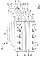
- the fuel cell assembly 10 shown in exploded form in Figure 1 has a typical structure which may be used with a gas separator in accordance with the present invention. As illustrated, the overall structure is known and will therefore not be described in detail.
- the assembly comprises a planar fuel cell 12 comprising a solid oxide electrolyte central layer 14 with an integral anode layer 16 overlying one face of the electrolyte and an integral cathode layer 18 overlying the opposite face of the electrolyte.
- the electrode layers may be applied by known screenprinting techniques.
- the fuel cell is sandwiched between a pair of gas separator plates 20 and 22 which in use are in face to face contact with the anode 16 and cathode 18 respectively.
- the gas separator plates 20 and 22 shown in Figure 1 are identical with an array of gaseous fuel channels 24 extending across the underside 26 and an array of gaseous oxidant flow channels 28 extending across the top side 30.
- the channels 24 and 28 are shown extending at right angles to each other but they may extend parallel and the respective gas flow directions may then be the same or opposite depending upon the manifolding arrangements.
- the gas separator plates 20 and 22 may be used to form a fuel cell stack in which an identical fuel cell 12 overlies the gas separator plate 20 and another identical fuel cell 12 underlies the gas separator plate 22. Further identical gas separator plates may then be placed adjacent to the opposite sides of the further fuel cells, and so forth to build up a fuel cell stack of the desired number of fuel cells.
- the gas separator plates provided at the ends of the stack need only have one of the arrays of gas channels, gas channels 24 for the gas separator plate at the top of the stack as described and gas channels 28 for the gas separator plate at the bottom of the stack as described.
- gas channels 24 for the gas separator plate at the top of the stack as described
- gas channels 28 for the gas separator plate at the bottom of the stack as described.
- the proposed gas separator plates need only have the respective array of gas channels on the face in contact with the fuel cell.
- These end gas separator plates are commonly termed end plates.
- gas channels on one or both sides of the gas separator plates 20 and 22 may be replaced by a separate gas flow structure, such as a mesh, between the gas separator plate and the respective electrode.
- a separate gas flow structure such as a mesh
- the gaseous fuel and oxidant flows must be kept apart and suitable manifolding (not shown) is provided to ensure this.
- suitable manifolding (not shown) is provided to ensure this.
- this is conveniently provided by an inert cylindrical or other sleeve (not shown), for example of ceramic, which extends around the fuel cell stack with its axis normal to the gas flow channels 24 and 28 and with the corners 32 of the fuel cells 12 and the corners 34 of the gas separator plates sealed in contact with the annular inner surface of the sleeve.
- the fuel cell assembly is completed by terminals on the top and bottom end plates for attachment of the fuel cell or fuel cell stack to an external load.
- the fuel cell assembly 10 illustrated in Figure 1 is known and in the described embodiment the fuel cell 12 comprises a solid oxide electrolyte 14 of Y 2 O 3 -doped ZrO 2 as an ionic conductor while the electrodes 16 and 18 are at least primarily electronic conductors with the anode 16 comprising an Ni/ZrO 2 cermet and the cathode 18 comprising strontium doped lanthanum manganite (LSM).
- LSM strontium doped lanthanum manganite
- the fuel cell 12 may be replaced by a fuel cell in which the anode layer is the primary load bearing layer, for example as described in the aforementioned patent application WO 98/57384 .
- Other features described in that application including the proposals for reducing the compressive load on the anode side of the fuel cells, may be adopted for use with the present invention.
- the gas separator plates 20 and 22 may be formed of aluminium bronze or of copper or some other suitable copper alloy. In either case the plates 20 and 22 will in use have a layer of Al 2 O 3 on the cathode side 30 as well as on the anode side 26, at least in the case of the copper plates, if the fuel gas includes methane.
- the gas separator plate 22 is formed of copper metal and has a thickness of about 0.5 mm.
- the foil layers 29 and 31 are provided by wrapping the entire plate 22 in foil with an overlapped join at the edge faces perpendicular to the sides 30 and 26. In use in an oxidising atmosphere, a layer of alumina will form on the outer surface of the foil to electrically isolate the foil and the plate 22.
- the cathode side 30 of the plate may be coated with a dense layer of alumina having a thickness of about 100 ⁇ m which is electrically insulating.
- the alumina layer extends across the outermost surface of the cathode side 30 of the gas separator plate 22 including throughout the oxygen containing gas channels 28.
- an alumina layer having a thickness of about 2 ⁇ m is provided on the anode side 26 of the plate 22 throughout the gas channels 24.
- a layer of expanded metal silver mesh 36 having a thickness of about 100 ⁇ m extends over the cathode side 30 to be sandwiched between the cathode layer 18 and the gas separator plate 22.
- the mesh 36 permits oxygen-containing gas from the channels 28 to contact the cathode layer 18 and is sufficiently thin to deform under the compressive load of the assembled fuel cell assembly 10 and thereby comply to small surface irregularities in the cathode layer 18 and cathode side 30 of the gas separator plate.
- the electrical connection with the cathode layer 18 may be enhanced.
- the silver mesh 36 is in electrical contact with platinum collector wires 38 at opposed ends of the mesh leading to an external electrical circuit.
- a nickel mesh (not shown) is disposed between the gas separator plate 22 and the anode layer 16 of the adjacent fuel cell.
- the nickel mesh is also in electrical contact with the external electrical circuit.
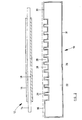
- a gas separator plate 122 has a construction generally the same as gas separator plate 22 shown in Figure 2 , but is formed of aluminium bronze.
- a layer of Al 2 O 3 will form on at least the cathode side of the plate 122.
- a conducting layer 136 on the cathode side is in the form of a woven mesh made from high temperature stainless steel which is silver plated. This mesh is electrically connected to the cathode side of the plate 122 by way of its corners contacting four slightly raised contacts 138.
- the contacts 138 are the silver plated heads of electrically conducting rivets which pass completely through the thickness of the plate 122 and therefore through the alumina layer formed on the cathode side of the plate.
- the opposite-facing rivet heads 142 are silver or silver-plated or nickel or nickel plated and these clamp a nickel or nickel plated conducting mesh 144 to the anode-facing side of the plate 122.
- the mesh 144 is pressed against the anode side of a fuel cell to make electrical contact therewith.
- the conduction path thus extends from the cathode side of a first fuel cell to mesh 136, then through the gas separator plate 122 via the four rivets to mesh 144, and from there to the anode side of a second fuel cell. It will be appreciated that this connection path is independent of the existence of the alumina layer or layers on the gas separator plate.
- Sealing of the annular clearance between the rivets and holes in the connector plate 122 through which the rivets pass may be accomplished by the rivet heads 138 bearing tightly on the cathode-facing side of plate 122.
- the clearance between the rivets and holes may be sealed with a glass which is viscous at the operating temperature of the gas separator plate.
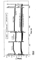
- each fuel cell assembly was substantially as described with reference to Figure 3 , except that two of the nickel meshes on the anode sides of the fuel cells were each replaced by copper mesh and the silver meshes were each replaced by platinum mesh. However, silver mesh could have been used in place of the platinum mesh.
- Each fuel cell comprised a solid oxide electrolyte of Y 2 O 3 -doped ZrO 2 as an ionic conductor, an anode comprising an Ni/ZrO 2 cermet and a cathode comprising strontium doped lanthanum manganite (LSM).
- Each gas separator between adjacent fuel cells and adjacent to the two end fuel cells was formed of self-aluminising heat resistant steel with gas channels formed on the side or sides facing the adjacent fuel cell or cells.
- a platinum mesh with platinum connectors was disposed between the cathode of each fuel cell and the adjacent gas separator, while a nickel mesh was disposed between the anodes of two of the fuel cells and the adjacent gas separators with a copper mesh between the anodes of the other two fuel cells and the adjacent gas separators, with all of the meshes in electrical contact with the adjacent electrodes.
- the fuel cells, gas separators and meshes were each 50 mm x 50 mm, with the copper mesh being woven and the nickel and platinum meshes being expanded meshes. All of the stainless steel gas separators had alumina coatings on both the anode side and the cathode side. Current take-offs were of platinum wire threaded through holes in the gas separators as described with reference to Figure 3 or welded to the terminal gas separators or end plates under the seal area.
- the fuel cell assembly was manifolded to prevent fuel gas and oxygen containing gas leakage and was tested at 900°C, at a current of three amps, with a fuel gas of humidified hydrogen containing 9.5% H 2 O and air as the oxygen containing gas.
- Figure 4 shows substantial stability of the voltage output over about 1000 hrs with very little difference between the voltages at the copper and nickel anode side current collectors.
- copper with an oxidation resistant coating on the cathode side, may be used as a gas separator in a fuel cell stack given the advantageous thermal conductivity properties of the metal.
- hydrogen is the fuel gas
- no other treatment or protective coating of the copper is required.
- methane is the fuel gas and nickel the anode material
- a protective coating will be required on the anode side of the copper gas separator.
- some other means will be required to prevent copper vapour escaping from the gas separator, such as alloying with aluminium.
- Other alloying metals, such as Be may also provide the same advantage.
- Al is preferred over Be on a cost basis and because the oxide of Be is highly toxic.
- a variety of protective coatings on copper or copper alloy sheets have also been tested to determine whether the coatings prevent copper vapour contaminating the nickel in a nickel zirconia cermet such as is used in fuel cell anodes.
- a protective layer comprising three layers of, respectively, tungsten followed by silver and then nickel were applied to a pure copper sheet.
- a protective layer comprising three layers of, respectively, tantalum followed by silver and then nickel was applied to a similar pure copper sheet.
- Each of the three layers in each test had a thickness of 2 to 3 microns.
- a similar pure copper sheet was wrapped in a self-aluminising heat resistant steel foil having a thickness of 50 microns.
- an aluminium bronze sheet was provided with an alumina surface coating by oxidising the sheet in air at 850°C for two hours.
- Each of these protected sheets was then placed face down on a nickel zirconia cermet substrate and weighted to ensure close physical contact between the protective layer of the copper or copper alloy sheet and the anode material.
- the structure was then heated at 900°C for one week in purge gas (4% H 2 in nitrogen).
- purge gas 4% H 2 in nitrogen.
- each structure was cooled and the nickel zirconia cermet substrates were investigated for copper contamination of the nickel. No such contamination was identified.
Landscapes
- Life Sciences & Earth Sciences (AREA)
- Engineering & Computer Science (AREA)
- Manufacturing & Machinery (AREA)
- Sustainable Development (AREA)
- Sustainable Energy (AREA)
- Chemical & Material Sciences (AREA)
- Chemical Kinetics & Catalysis (AREA)
- Electrochemistry (AREA)
- General Chemical & Material Sciences (AREA)
- Fuel Cell (AREA)
Applications Claiming Priority (3)
| Application Number | Priority Date | Filing Date | Title |
|---|---|---|---|
| AUPQ078899 | 1999-06-04 | ||
| AUPQ0788A AUPQ078899A0 (en) | 1999-06-04 | 1999-06-04 | A fuel cell gas separator |
| PCT/AU2000/000631 WO2000076015A1 (en) | 1999-06-04 | 2000-06-02 | A fuel cell gas separator |
Publications (3)
| Publication Number | Publication Date |
|---|---|
| EP1205001A1 EP1205001A1 (en) | 2002-05-15 |
| EP1205001A4 EP1205001A4 (en) | 2005-05-25 |
| EP1205001B1 true EP1205001B1 (en) | 2008-07-30 |
Family
ID=3814985
Family Applications (1)
| Application Number | Title | Priority Date | Filing Date |
|---|---|---|---|
| EP00930877A Expired - Lifetime EP1205001B1 (en) | 1999-06-04 | 2000-06-02 | A fuel cell gas separator |
Country Status (9)
| Country | Link |
|---|---|
| US (1) | US7150931B1 (enExample) |
| EP (1) | EP1205001B1 (enExample) |
| JP (1) | JP4667685B2 (enExample) |
| AT (1) | ATE403238T1 (enExample) |
| AU (1) | AUPQ078899A0 (enExample) |
| BR (1) | BR0011333B1 (enExample) |
| CA (1) | CA2375686C (enExample) |
| DE (1) | DE60039699D1 (enExample) |
| WO (1) | WO2000076015A1 (enExample) |
Families Citing this family (34)
| Publication number | Priority date | Publication date | Assignee | Title |
|---|---|---|---|---|
| EP1455404A2 (de) * | 2001-06-13 | 2004-09-08 | Bayerische Motoren Werke Aktiengesellschaft | Brennstoffzelle und Verfahren zur Herstellung einer solchen Brennstoffzelle |
| WO2003007403A1 (en) * | 2001-07-13 | 2003-01-23 | Ceramic Fuel Cells Limited | A fuel cell gas separator plate |
| US7008716B2 (en) | 2001-10-01 | 2006-03-07 | Delphi Technologies, Inc. | Gasket material for a fuel cell |
| US6821667B2 (en) * | 2001-10-01 | 2004-11-23 | Delphi Technologies, Inc. | Fuel cell stack having foil interconnects and laminated spacers |
| EP1376727A3 (en) * | 2002-05-29 | 2006-05-10 | Sanyo Electric Co., Ltd. | Solid oxide fuel cell |
| US8048587B2 (en) | 2002-11-27 | 2011-11-01 | Delphi Technologies, Inc. | Compliant current collector for fuel cell anode and cathode |
| US7314678B2 (en) | 2003-08-25 | 2008-01-01 | Corning Incorporated | Solid oxide fuel cell device with a component having a protective coatings and a method for making such |
| JP2005209470A (ja) * | 2004-01-22 | 2005-08-04 | Equos Research Co Ltd | 燃料電池 |
| JP4218569B2 (ja) * | 2004-03-30 | 2009-02-04 | 株式会社エクォス・リサーチ | セパレータ及びそれを用いた燃料電池 |
| US7427339B2 (en) * | 2004-10-15 | 2008-09-23 | Air Products And Chemicals, Inc. | Heat conducting metal layer for ion conductor stack |
| JP4887639B2 (ja) * | 2005-03-11 | 2012-02-29 | 株式会社エクォス・リサーチ | セパレータユニット及び燃料電池スタック |
| JP4992188B2 (ja) * | 2005-03-11 | 2012-08-08 | 株式会社エクォス・リサーチ | セパレータユニット及び燃料電池スタック |
| JP2007273303A (ja) * | 2006-03-31 | 2007-10-18 | Mitsubishi Materials Corp | 固体酸化物形燃料電池 |
| US8309264B2 (en) | 2006-12-08 | 2012-11-13 | Utc Fuel Cells, Llc | Fuel cell flow field having strong, chemically stable metal bipolar plates |
| FR2911219B1 (fr) * | 2007-01-09 | 2009-05-15 | Conception Dev Michelin S A | Plaque bipolaire pour pile a combustible a membrane polymere |
| US7754367B2 (en) | 2007-06-28 | 2010-07-13 | Delphi Technologies, Inc. | Solid bonded interconnect system in a lightweight solid oxide fuel cell stack |
| JP5139850B2 (ja) * | 2008-03-14 | 2013-02-06 | 株式会社日立製作所 | 固体酸化物形燃料電池 |
| KR100968505B1 (ko) * | 2008-09-08 | 2010-07-07 | 한국과학기술원 | 금속지지체형 고체산화물 연료전지 및 그 제조 방법 |
| KR101008212B1 (ko) * | 2008-09-08 | 2011-01-17 | 한국과학기술원 | 고체산화물 연료전지 |
| CN105206791A (zh) * | 2008-11-07 | 2015-12-30 | Sakti3有限公司 | 一体式结构中的多个电化学和聚能组件的制造方法和结构 |
| JP5334559B2 (ja) | 2008-12-19 | 2013-11-06 | 本田技研工業株式会社 | 燃料電池 |
| KR100979052B1 (ko) | 2008-12-23 | 2010-08-30 | 주식회사 포스코 | 평판형 고체산화물 연료전지용 분리판, 이를 포함하는 연료전지 및 이들의 제조방법 |
| US10160697B2 (en) * | 2012-08-21 | 2018-12-25 | Uop Llc | Methane conversion apparatus and process using a supersonic flow reactor |
| US10029957B2 (en) * | 2012-08-21 | 2018-07-24 | Uop Llc | Methane conversion apparatus and process using a supersonic flow reactor |
| US9689615B2 (en) * | 2012-08-21 | 2017-06-27 | Uop Llc | Steady state high temperature reactor |
| US9656229B2 (en) * | 2012-08-21 | 2017-05-23 | Uop Llc | Methane conversion apparatus and process using a supersonic flow reactor |
| US9707530B2 (en) * | 2012-08-21 | 2017-07-18 | Uop Llc | Methane conversion apparatus and process using a supersonic flow reactor |
| JP2016066504A (ja) * | 2014-09-25 | 2016-04-28 | 東邦瓦斯株式会社 | 燃料極用集電材および固体酸化物形燃料電池 |
| CN115566219A (zh) | 2016-08-11 | 2023-01-03 | 新兴电力公司 | 平面固体氧化物燃料电池单元、堆、堆单元和系统 |
| US11121382B2 (en) * | 2018-01-08 | 2021-09-14 | Cummins Enterprise, Llc | Solid oxide fuel cell stacks having a barrier layer and associated methods thereof |
| AU2020329309A1 (en) | 2019-08-14 | 2022-03-03 | Upstart Power, Inc. | SOFC-conduction |
| JP2023026218A (ja) * | 2021-08-13 | 2023-02-24 | 東芝エネルギーシステムズ株式会社 | 電気化学スタック用金属部材及び電気化学スタック |
| JP7705315B2 (ja) * | 2021-09-06 | 2025-07-09 | 東芝エネルギーシステムズ株式会社 | 保護層付きインターコネクタ、この保護層付きインターコネクタを具備するセルスタックならびに水素エネルギーシステム |
| JP2023151439A (ja) * | 2022-03-31 | 2023-10-16 | 京セラ株式会社 | 導電部材、電気化学セル装置、モジュールおよびモジュール収容装置 |
Family Cites Families (19)
| Publication number | Priority date | Publication date | Assignee | Title |
|---|---|---|---|---|
| JPS60154470A (ja) * | 1984-01-23 | 1985-08-14 | Toshiba Corp | 燃料電池 |
| GB2201624B (en) * | 1986-06-20 | 1990-10-17 | Nisshin Steel Co Ltd | Vibration-damping metal sheets |
| JP3064023B2 (ja) * | 1991-02-22 | 2000-07-12 | 三菱重工業株式会社 | 燃料電池用ガスセパレータ |
| JP2955069B2 (ja) * | 1991-07-17 | 1999-10-04 | 三菱重工業株式会社 | ガスセパレータの製造方法 |
| JP3122955B2 (ja) * | 1992-05-20 | 2001-01-09 | 新日本製鐵株式会社 | 溶融炭酸塩型燃料電池 |
| US5232792A (en) * | 1992-08-21 | 1993-08-03 | M-C Power Corporation | Cell separator plate used in fuel cell stacks |
| JP3321888B2 (ja) * | 1993-03-12 | 2002-09-09 | 住友金属工業株式会社 | 固体電解質型燃料電池用金属材料 |
| JP3416209B2 (ja) | 1993-07-30 | 2003-06-16 | 三洋電機株式会社 | 固体電解質型燃料電池 |
| RU2174728C2 (ru) * | 1994-10-12 | 2001-10-10 | Х Пауэр Корпорейшн | Топливный элемент, использующий интегральную технологию пластин для распределения жидкости |
| DE19523637C2 (de) | 1994-12-27 | 1997-08-14 | Mtu Friedrichshafen Gmbh | Verfahren zur Herstellung einer Korrosionsschutzbeschichtung, Substrat mit einer Korrosionsschutzbeschichtung sowie Verwendung eines solchen Substrats |
| AUPN173595A0 (en) * | 1995-03-15 | 1995-04-06 | Ceramic Fuel Cells Limited | Fuel cell interconnect device |
| EP0840947B1 (de) * | 1995-07-21 | 1999-01-07 | Siemens Aktiengesellschaft | Hochtemperatur-brennstoffzelle und hochtemperatur-brennstoffzellenstapel mit verbundleiterplatten, die eine kontaktschicht aus chromspinell tragen |
| JP3755545B2 (ja) * | 1995-11-30 | 2006-03-15 | 東燃ゼネラル石油株式会社 | 複合セラミックス、それを含有するセパレータ及び該セパレータを用いた固体電解質型燃料電池 |
| DE19547699C2 (de) | 1995-12-20 | 2000-01-13 | Forschungszentrum Juelich Gmbh | Bipolare Platte mit selektiver Beschichtung |
| AUPN876896A0 (en) * | 1996-03-18 | 1996-04-18 | Ceramic Fuel Cells Limited | An electrical interconnect for a planar fuel cell |
| JPH1092446A (ja) | 1996-09-13 | 1998-04-10 | Fuji Electric Corp Res & Dev Ltd | 固体電解質型燃料電池 |
| AUPO897897A0 (en) * | 1997-09-05 | 1997-09-25 | Ceramic Fuel Cells Limited | An interconnect device for a fuel cell assembly |
| DE29807832U1 (de) * | 1998-04-30 | 1998-07-02 | Siemens AG, 80333 München | Hochtemperatur-Brennstoffzelle und Hochtemperatur-Brennstoffzellenstapel |
| JP4707786B2 (ja) * | 1998-05-07 | 2011-06-22 | トヨタ自動車株式会社 | 燃料電池用ガスセパレータの製造方法 |
-
1999
- 1999-06-04 AU AUPQ0788A patent/AUPQ078899A0/en not_active Abandoned
-
2000
- 2000-06-02 AT AT00930877T patent/ATE403238T1/de not_active IP Right Cessation
- 2000-06-02 WO PCT/AU2000/000631 patent/WO2000076015A1/en not_active Ceased
- 2000-06-02 BR BRPI0011333-6A patent/BR0011333B1/pt not_active IP Right Cessation
- 2000-06-02 DE DE60039699T patent/DE60039699D1/de not_active Expired - Lifetime
- 2000-06-02 CA CA002375686A patent/CA2375686C/en not_active Expired - Fee Related
- 2000-06-02 JP JP2001502186A patent/JP4667685B2/ja not_active Expired - Fee Related
- 2000-06-02 US US09/980,956 patent/US7150931B1/en not_active Expired - Fee Related
- 2000-06-02 EP EP00930877A patent/EP1205001B1/en not_active Expired - Lifetime
Also Published As
| Publication number | Publication date |
|---|---|
| BR0011333B1 (pt) | 2011-01-25 |
| CA2375686A1 (en) | 2000-12-14 |
| AUPQ078899A0 (en) | 1999-06-24 |
| CA2375686C (en) | 2009-08-11 |
| EP1205001A1 (en) | 2002-05-15 |
| DE60039699D1 (de) | 2008-09-11 |
| EP1205001A4 (en) | 2005-05-25 |
| WO2000076015A1 (en) | 2000-12-14 |
| ATE403238T1 (de) | 2008-08-15 |
| JP4667685B2 (ja) | 2011-04-13 |
| US7150931B1 (en) | 2006-12-19 |
| JP2003501796A (ja) | 2003-01-14 |
| BR0011333A (pt) | 2002-03-05 |
Similar Documents
| Publication | Publication Date | Title |
|---|---|---|
| EP1205001B1 (en) | A fuel cell gas separator | |
| US6444340B1 (en) | Electrical conductivity in a fuel cell assembly | |
| US6280868B1 (en) | Electrical interconnect for a planar fuel cell | |
| EP0750798B1 (en) | Solid oxide fuel cell stacking assembly | |
| EP1384280A2 (en) | Metal-supported solid electrolyte electrochemical cell and multi cell reactors incorporating same | |
| JPH11162478A (ja) | 燃料電池用セパレータ | |
| JP4573526B2 (ja) | 固体酸化物形燃料電池 | |
| US7037617B2 (en) | Conductive coatings for PEM fuel cell electrodes | |
| EP1147070B1 (en) | Electrically conductive ceramic layers | |
| US8071252B2 (en) | Interconnector for high-temperature fuel cells | |
| JP4462050B2 (ja) | 固体酸化物形燃料電池 | |
| JP5283323B2 (ja) | 燃料電池用インターコネクタ及びセルスタック | |
| JP2006107936A (ja) | 平板形固体酸化物燃料電池用インターコネクタ | |
| JP2004281353A (ja) | 燃料電池用セパレータ | |
| AU781776B2 (en) | A fuel cell gas separator | |
| JP5170815B2 (ja) | 固体電解質型燃料電池ユニット及びスタック | |
| JP4984374B2 (ja) | 燃料電池 | |
| JP5017857B2 (ja) | 燃料電池用のセパレータおよび固体酸化物形燃料電池 | |
| US7575827B2 (en) | Conductive coatings for PEM fuel cell electrodes | |
| EP1735864B1 (en) | Electrolyte electrode assembly and method of producing the same | |
| CN118765449A (zh) | 制造管状固体氧化物燃料电池的方法和电池组 | |
| JPH04282566A (ja) | 固体電解質型燃料電池用インターコネクター及びこれを有する固体電解質型燃料電池 |
Legal Events
| Date | Code | Title | Description |
|---|---|---|---|
| PUAI | Public reference made under article 153(3) epc to a published international application that has entered the european phase |
Free format text: ORIGINAL CODE: 0009012 |
|
| 17P | Request for examination filed |
Effective date: 20011217 |
|
| AK | Designated contracting states |
Kind code of ref document: A1 Designated state(s): AT BE CH CY DE DK ES FI FR GB GR IE IT LI LU MC NL PT |
|
| AX | Request for extension of the european patent |
Free format text: AL;LT;LV;MK;RO;SI |
|
| A4 | Supplementary search report drawn up and despatched |
Effective date: 20050413 |
|
| RIC1 | Information provided on ipc code assigned before grant |
Ipc: 7H 01M 8/10 A Ipc: 7H 01M 8/12 B Ipc: 7H 01M 8/02 B |
|
| 17Q | First examination report despatched |
Effective date: 20061020 |
|
| GRAP | Despatch of communication of intention to grant a patent |
Free format text: ORIGINAL CODE: EPIDOSNIGR1 |
|
| GRAS | Grant fee paid |
Free format text: ORIGINAL CODE: EPIDOSNIGR3 |
|
| GRAA | (expected) grant |
Free format text: ORIGINAL CODE: 0009210 |
|
| AK | Designated contracting states |
Kind code of ref document: B1 Designated state(s): AT BE CH CY DE DK ES FI FR GB GR IE IT LI LU MC NL PT SE |
|
| REG | Reference to a national code |
Ref country code: GB Ref legal event code: FG4D |
|
| REG | Reference to a national code |
Ref country code: CH Ref legal event code: EP |
|
| REF | Corresponds to: |
Ref document number: 60039699 Country of ref document: DE Date of ref document: 20080911 Kind code of ref document: P |
|
| REG | Reference to a national code |
Ref country code: IE Ref legal event code: FG4D |
|
| PG25 | Lapsed in a contracting state [announced via postgrant information from national office to epo] |
Ref country code: PT Free format text: LAPSE BECAUSE OF FAILURE TO SUBMIT A TRANSLATION OF THE DESCRIPTION OR TO PAY THE FEE WITHIN THE PRESCRIBED TIME-LIMIT Effective date: 20081230 Ref country code: NL Free format text: LAPSE BECAUSE OF FAILURE TO SUBMIT A TRANSLATION OF THE DESCRIPTION OR TO PAY THE FEE WITHIN THE PRESCRIBED TIME-LIMIT Effective date: 20080730 Ref country code: ES Free format text: LAPSE BECAUSE OF FAILURE TO SUBMIT A TRANSLATION OF THE DESCRIPTION OR TO PAY THE FEE WITHIN THE PRESCRIBED TIME-LIMIT Effective date: 20081110 |
|
| PG25 | Lapsed in a contracting state [announced via postgrant information from national office to epo] |
Ref country code: FI Free format text: LAPSE BECAUSE OF FAILURE TO SUBMIT A TRANSLATION OF THE DESCRIPTION OR TO PAY THE FEE WITHIN THE PRESCRIBED TIME-LIMIT Effective date: 20080730 Ref country code: AT Free format text: LAPSE BECAUSE OF FAILURE TO SUBMIT A TRANSLATION OF THE DESCRIPTION OR TO PAY THE FEE WITHIN THE PRESCRIBED TIME-LIMIT Effective date: 20080730 |
|
| PG25 | Lapsed in a contracting state [announced via postgrant information from national office to epo] |
Ref country code: BE Free format text: LAPSE BECAUSE OF FAILURE TO SUBMIT A TRANSLATION OF THE DESCRIPTION OR TO PAY THE FEE WITHIN THE PRESCRIBED TIME-LIMIT Effective date: 20080730 |
|
| PG25 | Lapsed in a contracting state [announced via postgrant information from national office to epo] |
Ref country code: DK Free format text: LAPSE BECAUSE OF FAILURE TO SUBMIT A TRANSLATION OF THE DESCRIPTION OR TO PAY THE FEE WITHIN THE PRESCRIBED TIME-LIMIT Effective date: 20080730 |
|
| PLBE | No opposition filed within time limit |
Free format text: ORIGINAL CODE: 0009261 |
|
| STAA | Information on the status of an ep patent application or granted ep patent |
Free format text: STATUS: NO OPPOSITION FILED WITHIN TIME LIMIT |
|
| 26N | No opposition filed |
Effective date: 20090506 |
|
| PG25 | Lapsed in a contracting state [announced via postgrant information from national office to epo] |
Ref country code: MC Free format text: LAPSE BECAUSE OF NON-PAYMENT OF DUE FEES Effective date: 20090630 Ref country code: SE Free format text: LAPSE BECAUSE OF FAILURE TO SUBMIT A TRANSLATION OF THE DESCRIPTION OR TO PAY THE FEE WITHIN THE PRESCRIBED TIME-LIMIT Effective date: 20081030 |
|
| REG | Reference to a national code |
Ref country code: CH Ref legal event code: PL |
|
| PG25 | Lapsed in a contracting state [announced via postgrant information from national office to epo] |
Ref country code: IE Free format text: LAPSE BECAUSE OF NON-PAYMENT OF DUE FEES Effective date: 20090602 Ref country code: LI Free format text: LAPSE BECAUSE OF NON-PAYMENT OF DUE FEES Effective date: 20090630 Ref country code: CH Free format text: LAPSE BECAUSE OF NON-PAYMENT OF DUE FEES Effective date: 20090630 |
|
| PG25 | Lapsed in a contracting state [announced via postgrant information from national office to epo] |
Ref country code: GR Free format text: LAPSE BECAUSE OF FAILURE TO SUBMIT A TRANSLATION OF THE DESCRIPTION OR TO PAY THE FEE WITHIN THE PRESCRIBED TIME-LIMIT Effective date: 20081031 |
|
| PG25 | Lapsed in a contracting state [announced via postgrant information from national office to epo] |
Ref country code: LU Free format text: LAPSE BECAUSE OF NON-PAYMENT OF DUE FEES Effective date: 20090602 |
|
| PG25 | Lapsed in a contracting state [announced via postgrant information from national office to epo] |
Ref country code: CY Free format text: LAPSE BECAUSE OF FAILURE TO SUBMIT A TRANSLATION OF THE DESCRIPTION OR TO PAY THE FEE WITHIN THE PRESCRIBED TIME-LIMIT Effective date: 20080730 |
|
| PGFP | Annual fee paid to national office [announced via postgrant information from national office to epo] |
Ref country code: GB Payment date: 20140618 Year of fee payment: 15 |
|
| PGFP | Annual fee paid to national office [announced via postgrant information from national office to epo] |
Ref country code: IT Payment date: 20140624 Year of fee payment: 15 Ref country code: DE Payment date: 20140619 Year of fee payment: 15 |
|
| PGFP | Annual fee paid to national office [announced via postgrant information from national office to epo] |
Ref country code: FR Payment date: 20140619 Year of fee payment: 15 |
|
| REG | Reference to a national code |
Ref country code: DE Ref legal event code: R119 Ref document number: 60039699 Country of ref document: DE |
|
| PG25 | Lapsed in a contracting state [announced via postgrant information from national office to epo] |
Ref country code: IT Free format text: LAPSE BECAUSE OF NON-PAYMENT OF DUE FEES Effective date: 20150602 |
|
| GBPC | Gb: european patent ceased through non-payment of renewal fee |
Effective date: 20150602 |
|
| REG | Reference to a national code |
Ref country code: FR Ref legal event code: ST Effective date: 20160229 |
|
| PG25 | Lapsed in a contracting state [announced via postgrant information from national office to epo] |
Ref country code: DE Free format text: LAPSE BECAUSE OF NON-PAYMENT OF DUE FEES Effective date: 20160101 Ref country code: GB Free format text: LAPSE BECAUSE OF NON-PAYMENT OF DUE FEES Effective date: 20150602 |
|
| PG25 | Lapsed in a contracting state [announced via postgrant information from national office to epo] |
Ref country code: FR Free format text: LAPSE BECAUSE OF NON-PAYMENT OF DUE FEES Effective date: 20150630 |